background image

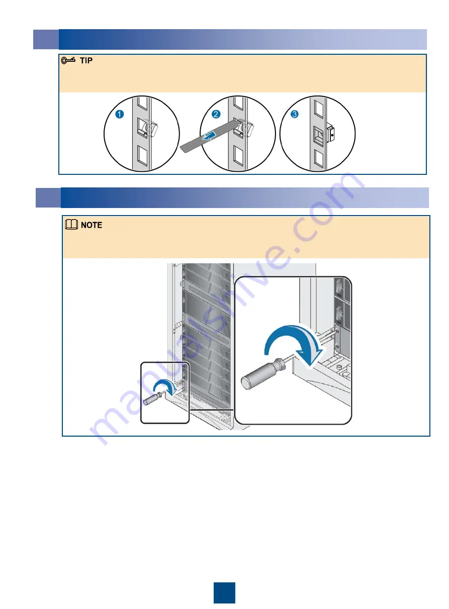
Installing Floating Nuts 

To ensure good ventilation, it is recommended to cover the unoccupied slots with filler panels. Before 
installing the filler panels, check that required floating nuts are installed at the installation holes of the 
M6 fixing screws. 

Installing Filler Panels 

If you do not have a floating nut mounting bar, you can use a flat-head screwdriver instead. When 
using a flat-head screwdriver to install the floating nuts, handle it gently; otherwise, the flat-head 
screwdriver may skid, and injure the hands or storage devices. 

Summary of Contents for OceanStor Dorado2100 G2

Page 1: ... during power on To avoid device damage ensure that the devices are properly grounded before power on Copyright Huawei Technologies Co Ltd 2012 All rights reserved Safety Information To avoid personal injuries it is recommended to carry one fully configured controller enclosure or disk enclosure by three persons Before handling devices wear ESD clothes ESD gloves or ESD wrist strap and take off co...

Page 2: ...ctric current of the circuit breakers of the external power supplies to which the storage device is connected complies with the following specifications Controller enclosure 2 U Adjustable guide rails Front panel 2 U Multi mode optical fiber Network cable The above table only includes part of the materials to be used during the installation For information about all the materials see the Packing L...

Page 3: ...culated through the following formula 2 U 2 U x number of 2 U disk enclosures Figure 1 Figure 2 If the planned device installation positions are occupied by filler panels remove them in the method shown in Figure 1 After removing the filler panels remove floating nuts in the method shown in Figure 2 If the floating nut mounting bar is unavailable you can use a flat head screwdriver instead When us...

Page 4: ... adjustable guide rails are initially equipped with positioning pins applicable to square installation holes only For round installation holes replace the positioning pins After the left adjustable guide rail is installed install the right adjustable guide rail in the same method To avoid device damage do not directly pile up the devices but install the devices onto the guide rails 6 Installing th...

Page 5: ... required floating nuts are installed at the installation holes of the M6 fixing screws 8 Installing Filler Panels If you do not have a floating nut mounting bar you can use a flat head screwdriver instead When using a flat head screwdriver to install the floating nuts handle it gently otherwise the flat head screwdriver may skid and injure the hands or storage devices ...

Page 6: ...e general view of cable connecting ports using the AC controller enclosure configured with 10 Gb TOE host ports as an example After connecting one end of the ground cable to the ground terminal of the storage device connect the other end of the ground cable to the ground terminal of the cabinet in the same method ...

Page 7: ...n port on the controller enclosure can be connected to a maximum of three disk enclosures each of which supports up to 25 disks The bend radius of the mini SAS cable should be larger than 150 mm 5 91 inches If the controller enclosure is connected to one or two disk enclosures Expansion module on controller A must connect to expansion module A on each disk enclosure Expansion module on controller ...

Page 8: ...rt on the maintenance terminal using a network cable so that the maintenance terminal can manage and maintain the storage device For details about each port and the cable connected to it see the OceanStor Dorado2100 G2 Storage System Installation Guide After connecting the serial port to the maintenance terminal using a serial cable you can manage and maintain the storage system through the serial...

Page 9: ...nnecting AC power cables Complete view of the connected AC power cables The AC device is allowed to connect to AC power supplies only and the DC device is allowed to connect to DC power supplies only The AC power modules and DC power modules of the storage system can connect to two routes of power supplies To ensure the high availability of the storage system and avoid unexpected power down of the...

Page 10: ...t it connects IB cable The IB cable is fully inserted into the IB host port The IB cable is loose in the IB host port Network cable The network cable is fully inserted into the management network port The network cable is loose in the management network port AC power cable The AC power cables for each controller enclosure or disk enclosure are connected to two separate power sources redundantly Th...

Page 11: ...e status indicators after the devices are powered on When the storage system is powered on the colors of the indicators vary with the port speeds For details see the OceanStor Dorado2100 G2 Storage System Installation Guide 2 Pressing the Power Button on Controller Enclosure Power indicator of the controller enclosure Green on Green on Disk running indicator Each controller enclosure has a hot spa...

Page 12: ...reen on Green on Blue on Link Speed indicator of the 8 Gb FC host port Blue on Green on Link indicator of the mini SAS expansion port Blue on Link Speed indicator of the 10 Gb TOE host port Running indicator of the interface module Power running alarm indicator Green on Fan running alarm indicator Power indicator of the expansion module Green on Link indicator of the PRI expansion port Green on Bl...

Page 13: ...min storage You are advised to change the default login password immediately after you have logged in to the storage system for the first time and to periodically change your login password in the future This reduces the password leakage risks For details on how to initialize the storage system see the OceanStor Dorado2100 Storage System Installation Guide If faults occur during power on seek help...

Reviews: