background image


8 Optical Module 


Issue    () 

Huawei Proprietary and Confidential                                     

Copyright © Huawei Technologies Co., Ltd. 

298 


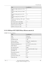
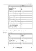
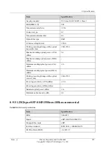
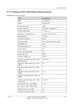
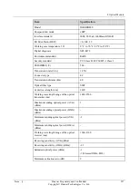
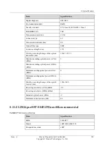
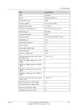
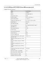
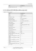
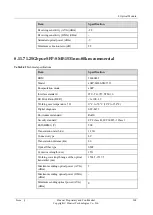
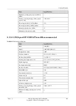
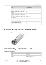
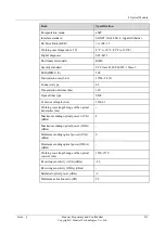
8.10.6 1.25Gbps-eSFP-SMF-1310nm-40km-commercial 

Table 8-33


Technical specifications 

Item 

Specification 

BOM 

34060539 

Model 

OGEBIDI41 

Encapsulation mode 

eSFP 

Interface standard 

IEEE 802.3ah, 1000Base-BX40-U 

Bit Error Ratio (BER) 

<1x10E–12 

Working case temperature (°C) 

0 °C to 70 °C (32°F to 158°F) 

Digital diagnosis 

SFF-8472 

Environment standard 

RoHS 

Security standard 

FCC class B, IEC 60825-1 Class 1 

ESD(HBM1) (V) 

500 

Transmission rate (bit/s) 

1.25G 

Connector type 

LC 

Transmission distance (km) 

40 

Optical fiber type 

SMF 

Center wavelength (nm) 

1310 

Working wavelength range of the optical 
transmitter (nm) 

1260-1360 

Maximum sending optical power (AVG) 
(dBm) 

Maximum sending optical power (OMA) 
(dBm) 

Minimum sending optical power (AVG) 
(dBm) 

-2 

Minimum sending optical power (OMA) 
(dBm) 

Working wavelength range of the optical 
receiver (nm) 

1480-1500 

Receiving sensitivity (AVG) (dBm) 

Receiving sensitivity (OMA) (dBm) 

-23 

Saturated optical power (dBm) 

-3 

-3(Stressed OMA, EOL) 

Summary of Contents for NE20E-S Series

Page 1: ...HUAWEI NE20E S Universal Service Router Hardware Description Issue Date HUAWEI TECHNOLOGIES CO LTD ...

Page 2: ...mer All or part of the products services and features described in this document may not be within the purchase scope or the usage scope Unless otherwise specified in the contract all statements information and recommendations in this document are provided AS IS without warranties guarantees or representations of any kind either express or implied The information in this document is subject to cha...

Page 3: ... object as the standard Related Version The following table lists the product version related to this document Product Name Version NE20E S Series V800R010C00 U2000 V200R017C60 Intended Audience This document is intended for Network planning engineers Hardware installation engineers Commissioning engineers On site maintenance engineers System maintenance engineers Security Declaration Encryption a...

Page 4: ...t and error detection purposes Huawei cannot offer services to collect or store this information unilaterally Before enabling the function ensure that it is performed within the boundaries permitted by applicable laws and regulations Effective measures must be taken to ensure that information is securely protected Reliability design declaration Network planning and site design must comply with rel...

Page 5: ... which if not avoided may result in minor or moderate injury Indicates a potentially hazardous situation which if not avoided could result in equipment damage data loss performance deterioration or unanticipated results NOTICE is used to address practices not related to personal injury Calls attention to important information best practices and tips NOTE is used to address information not related ...

Page 6: ... 8 66 in x 8 66 in 5U AC 264 mm x 220 mm x 442 mm 10 39 in x 8 66 in x 8 66 in 6U 353 mm x 220 mm x 442 mm 13 9 in x 8 66 in x 8 66 in 8U Weight empty DC 4 4 kg 9 68 lb AC 5 5 kg 12 13 lb DC 7 1 kg 15 66 lb AC 8 5 kg 18 74 lb 11 5 kg 25 36 lb DC 7 1 kg 15 66 lb AC 8 5 kg 18 74 lb 11 5 kg 25 36 lb Weight full configu ration DC 13 7 kg 30 21 lb AC 18 1 kg 39 91 lb NSP A DC 21 5 kg 47 41 lb NSP A AC ...

Page 7: ...TU hour DC 2092 7 BTU hour NSP A full configurati on AC 2280 8 BTU hour NSP A full configurati on DC 2258 1 BTU hour NSP A full configurat ion AC 2400 9 BTU hour NSP A full configurat ion 3276 9 BTU hour N SP C full configuration 3478 BTU hour N SP C full configuratio n DC input voltage input voltage range 40 V to 72V input rated voltage 4 8V 60V input voltage range 40V to 72V input rated voltage ...

Page 8: ...MPUE sing le core1 2 G MPUE1 eig ht core1 5 G MPUE sin gle core1 2 G MPUE1 e ight core1 5 G MPUE1 eight core1 5 G MPUE1 eigh t core1 5 G Flash MPU 16 MB MPU 16 MB MPU 16 MB MPU 16 MB MPU 16 MB SDRA M MPUE 2 GB MPUE1 8 GB MPUE 2 GB MPUE1 8 GB MPUE 2 GB MPUE1 8 GB MPUE1 8 GB MPUE1 8 GB Storage 2GB eUSB 2 GB eUSB 2 GB eUSB 2 GB eUSB 2 GB eUSB Redund ant MPUs 1 1 1 1 1 1 1 1 1 1 Redund ant NSPs 1 1 1 ...

Page 9: ... Gbps NS P C 100 Gbps NSP 50 240 Gbps NSP 120 240 Gbps NSP A 480 Gbps NSP B 960 Gbps NSP C 100 Gbps NS P 50 240 Gbps NS P 120 240 Gbps NS P A 480 Gbps NS P B 960 Gbps NS P C Operati ng temper ature Long term 0 C to 45 C 32 F to 113 F Short ter m 5 C to 55 C 23 F to 131 F Enhance DC 40 C to 65 C 20 C start Remark R estriction on the temperatu re Long term 0 C to 45 C 32 F to 113 F Short term 5 C to...

Page 10: ...t ter m 5 to 95 RH non conde nsing Long term 5 to 85 RH non conden sing Short term 5 to 95 RH non conden sing Long ter m 5 to 85 RH non conde nsing Short ter m 5 to 95 RH non conde nsing Long term 5 to 85 RH non conde nsing Short ter m 5 to 95 RH non conde nsing Long ter m 5 to 85 RH non cond ensing Short ter m 5 to 95 RH non cond ensing Relativ e storage humidit y 5 to 95 RH non condensi ng 5 to ...

Page 11: ...ng products and versions BO M Module Descript ion NE20E S4 NE20E S8 NE20E S16 NE20E S8A NE20E S16A 030 30Q CX CR2D00 MPUE10 7 2 2 Main Processin g Unit E 030 31E DQ CR2D0M PUE110 7 2 3 Main Processin g Unit E1 030 30Q GY CR2D0N SP5010 7 3 2 Network Service Processor NSP 50 030 30Q HA CR2DNS PE5010 7 3 3 Network Service Processor NSP 50 E 030 30R FH CR2DNS P12010 7 3 4 Network Service Processor NSP...

Page 12: ...ervice Processor NSP A 030 31D BX CR2DNS PB0010 7 3 7 Network Service Processor NSP B 030 31Y CJ CR2DNS PC0010 7 3 8 Network Service Processor NSP C 030 32A ML CR2D00 E1NC10 7 4 6 1 Port 100GBas e CFP2 Physical Interface Card PIC 030 32A MM CR2D00 LAXF10 7 4 7 10 Port 10GBase LAN W AN SFP Physical Interface Card PIC 030 31L PW CR2D00 E1MF70 7 4 22 1 Port 40GBase CFP Physical Interface Card PIC 030...

Page 13: ...0 31D JQ CR2DL1 XE8G11 7 4 26 1 Port 10GBase LAN W AN SFP 8 Port 100 1000 Base X S FP Physical Interface Card 030 30W GQ CR2D00 L2XF12 7 4 27 2 Port 10GBase LAN W AN SFP Physical Interface Card 030 32C RN CR2D0L 2XFH11 7 4 38 2 Port 10GBase LAN W AN SFP Physical Interface Card H 030 31D HB CR2D00 E8GE12 7 4 23 8 Port 100 1000 Base RJ4 5 Physical Interface Card 030 31D JK CR2D00 EAGF10 7 4 24 10 Po...

Page 14: ...RP CR2D0E 8GFH10 7 4 39 8 Port 100 1000 Base X S FP Physical Interface Card H 030 31X CH CR2D00 EEGF10 7 4 40 20 Port 100 1000 Base X S FP Physical Interface Card 030 30R JQ CR5D08 CWDM7 0 7 4 37 8 Channe l CWDM Multiple xing Demultip lexing 1471 14 91 1511 1531 155 1 1571 1 591 1611 nm Physical Interface Card PIC 030 32E EY CR5D1D MD1M0 1 7 4 8 Bidirecti onal 1 Channe l CWDM Optical Add Dro p Mul...

Page 15: ...face Card PIC 030 32E FA CR5D1D MD1M0 2 7 4 9 Bidirecti onal 1 Channe l CWDM Optical Add Dro p Multiple xing 1491nm Physical Interface Card PIC 030 32E FB CR5D1D MD1M0 3 7 4 10 Bidirecti onal 1 Channe l CWDM Optical Add Dro p Multiple xing 1511nm Physical Interface Card PIC 030 32E FC CR5D1D MD1M0 4 7 4 11 Bidirecti onal 1 Channe l CWDM Optical Add Dro p Multiple xing 1531nm Physical Interface ...

Page 16: ...30 32E FD CR5D1D MD1M0 5 7 4 12 Bidirecti onal 1 Channe l CWDM Optical Add Dro p Multiple xing 1551nm Physical Interface Card PIC 030 32E FE CR5D1D MD1M0 6 7 4 13 Bidirecti onal 1 Channe l CWDM Optical Add Dro p Multiple xing 1571nm Physical Interface Card PIC 030 32E FF CR5D1D MD1M0 7 7 4 14 Bidirecti onal 1 Channe l CWDM Optical Add Dro p Multiple xing 1591nm Physical Interface Card PIC ...

Page 17: ...15 Bidirecti onal 1 Channe l CWDM Optical Add Dro p Multiple xing 1611nm Physical Interface Card PIC 030 32E FH CR5D2D MD2M0 1 7 4 16 Bidirecti onal 2 Channe l CWDM Optical Add Dro p Multiple xing 1471 14 91nm Physical Interface Card PIC 030 32E FJ CR5D2D MD2M0 2 7 4 17 Bidirecti onal 2 Channe l CWDM Optical Add Dro p Multiple xing 1511 15 31nm Physical Interface Card PIC 030 32E CR5D2D MD2M0 7 4 ...

Page 18: ...l Add Dro p Multiple xing 1551 15 71nm Physical Interface Card PIC 030 32E FL CR5D2D MD2M0 4 7 4 19 Bidirecti onal 2 Channe l CWDM Optical Add Dro p Multiple xing 1591 16 11nm Physical Interface Card PIC 030 30Q CQ CR2D00 0IE110 7 4 29 32 Port E1 Physical Interface Card 75o hm 030 30Q CP CR2D00 0IE111 7 4 30 32 Port E1 Physical Interface Card 120 ohm 030 30R FA CR2D00 0DE110 7 4 31 16 Port E1 Phys...

Page 19: ...rt E1 Physical Interface Card 120 ohm 030 31W DR CR2D00 A2CF10 7 4 41 2 Port OC 3c S TM 1c ATM SF P Physical Interface Card 030 30Q CN CR2D00 C4CF11 7 4 28 4 Port Channeli zed STM 1c POS SFP Physical Interface Card PIC 030 30R ET CR2D00 P4CF11 7 4 33 4 Port OC 3c S TM 1c POS SFP Physical Interface Card 030 31D KA CR2DP2 C1HF11 7 4 34 2 Port OC 3c S TM 1c or 1 Port OC 12c STM 4C POS SFP Physical In...

Page 20: ...XQ10 7 4 36 Auxiliary Flexible Interface Card with 4 Port 100Base RJ45 FIC Sup porting 1588v2 The supported items of boards list in the Table 3 2 indicates supported items indicates unsupported items Table 3 2 Mapping products and versions B O M Modu le Descr iption NSP 5 0 NSP 5 0 E NSP 1 20 NSP 1 20 E NSP A NSP B NSP C 03 03 2A M L CR2D 00E1N C10 7 4 6 1 Port 100GB ase CF P2 Physic al Interfa ce...

Page 21: ...P 1 20 E NSP A NSP B NSP C Physic al Interfa ce Card P IC 03 03 1L P W CR2D 00E1 MF70 7 4 22 1 Port 40GBa se CF P Physic al Interfa ce Card P IC 03 03 1D JP CR2D 00L4X F11 7 4 25 4 Port 10GBa se LAN WAN SFP Physic al Interfa ce Card 03 03 1D JQ CR2D L1XE 8G11 7 4 26 1 Port 10GBa se LAN WAN SFP 8 Port 100 10 00Bas e X S FP Physic al Interfa ce Card 03 CR2D 7 4 27 ...

Page 22: ...B NSP C 03 0 W G Q 00L2X F12 2 Port 10GBa se LAN WAN SFP Physic al Interfa ce Card 03 03 2C R N CR2D 0L2XF H11 7 4 38 2 Port 10GBa se LAN WAN SFP Physic al Interfa ce Card H 03 03 1D H B CR2D 00E8G E12 7 4 23 8 Port 100 10 00Bas e RJ45 Physic al Interfa ce Card 03 03 1D JK CR2D 00EA GF10 7 4 24 10 Por t 100 10 00Bas e X S FP Physic al Interfa ce Card 03 03 CR2D 0E8GF 7 4 39 8 Port ...

Page 23: ... 1 20 E NSP A NSP B NSP C 2C RP H10 100 10 00Bas e X S FP Physic al Interfa ce Card H 03 03 1X C H CR2D 00EE GF10 7 4 40 20 Por t 100 10 00Bas e X S FP Physic al Interfa ce Card 03 03 0R JQ CR5D 08CW DM70 7 4 37 8 Cha nnel CWD M Multip lexing Demul tiplexi ng 1471 1491 1 511 15 31 155 1 1571 1591 1611n m Physic al Interfa ce Card P IC 03 03 CR5D 1DMD 7 4 8 Bidire ...

Page 24: ... 20 NSP 1 20 E NSP A NSP B NSP C 2E EY 1M01 ctional 1 Cha nnel CWD M Optica l Add D rop Multip lexing 1471n m Physic al Interfa ce Card P IC 03 03 2E FA CR5D 1DMD 1M02 7 4 9 Bidire ctional 1 Cha nnel CWD M Optica l Add D rop Multip lexing 1491n m Physic al Interfa ce Card P IC 03 03 2E FB CR5D 1DMD 1M03 7 4 10 Bidire ctional 1 Cha nnel CWD M Optica l Add D ...

Page 25: ...P 1 20 NSP 1 20 E NSP A NSP B NSP C rop Multip lexing 1511n m Physic al Interfa ce Card P IC 03 03 2E FC CR5D 1DMD 1M04 7 4 11 Bidire ctional 1 Cha nnel CWD M Optica l Add D rop Multip lexing 1531n m Physic al Interfa ce Card P IC 03 03 2E FD CR5D 1DMD 1M05 7 4 12 Bidire ctional 1 Cha nnel CWD M Optica l Add D rop Multip lexing 1551n m Physic al Interfa ...

Page 26: ... 20 E NSP A NSP B NSP C ce Card P IC 03 03 2E FE CR5D 1DMD 1M06 7 4 13 Bidire ctional 1 Cha nnel CWD M Optica l Add D rop Multip lexing 1571n m Physic al Interfa ce Card P IC 03 03 2E FF CR5D 1DMD 1M07 7 4 14 Bidire ctional 1 Cha nnel CWD M Optica l Add D rop Multip lexing 1591n m Physic al Interfa ce Card P IC 03 03 2E FG CR5D 1DMD 1M08 7 4 15 Bidire ctional 1 Cha ...

Page 27: ...E NSP 1 20 NSP 1 20 E NSP A NSP B NSP C nnel CWD M Optica l Add D rop Multip lexing 1611n m Physic al Interfa ce Card P IC 03 03 2E FH CR5D 2DMD 2M01 7 4 16 Bidire ctional 2 Cha nnel CWD M Optica l Add D rop Multip lexing 1471 1491n m Physic al Interfa ce Card P IC 03 03 2E FJ CR5D 2DMD 2M02 7 4 17 Bidire ctional 2 Cha nnel CWD M Optica l Add D rop ...

Page 28: ...P 1 20 NSP 1 20 E NSP A NSP B NSP C Multip lexing 1511 1531n m Physic al Interfa ce Card P IC 03 03 2E FK CR5D 2DMD 2M03 7 4 18 Bidire ctional 2 Cha nnel CWD M Optica l Add D rop Multip lexing 1551 1571n m Physic al Interfa ce Card P IC 03 03 2E FL CR5D 2DMD 2M04 7 4 19 Bidire ctional 2 Cha nnel CWD M Optica l Add D rop Multip lexing 1591 1611n m Physic ...

Page 29: ...Interfa ce Card P IC 03 03 0Q C Q CR2D 000IE 110 7 4 29 32 Por t E1 Physic al Interfa ce Card 7 5ohm 03 03 0Q CP CR2D 000IE 111 7 4 30 32 Por t E1 Physic al Interfa ce Card 1 20ohm 03 03 0R FA CR2D 000DE 110 7 4 31 16 Por t E1 Physic al Interfa ce Card 7 5ohm 03 03 0R EY CR2D 000DE 111 7 4 32 16 Por t E1 Physic al Interfa ce Card 1 20ohm 03 03 1 W D CR2D 00A2C F10 7 4 41 2 Port OC 3c STM 1c ...

Page 30: ... 20 E NSP A NSP B NSP C R ATM SFP Physic al Interfa ce Card 03 03 0Q C N CR2D 00C4C F11 7 4 28 4 Port Chann elized STM 1 c POS S FP Physic al Interfa ce Card P IC 03 03 0R ET CR2D 00P4C F11 7 4 33 4 Port OC 3c STM 1c POS S FP Physic al Interfa ce Card 03 03 1D K A CR2D P2C1 HF11 7 4 34 2 Port OC 3c STM 1c or 1 Port OC 12 c STM 4C POS S FP Physic al Interfa ce Card ...

Page 31: ...9 B O M Modu le Descr iption NSP 5 0 NSP 5 0 E NSP 1 20 NSP 1 20 E NSP A NSP B NSP C 03 03 1D K B CR2D 00C1C F11 7 4 35 1 Port Chann elized STM 1 c POS S FP Physic al Interfa ce Card 03 03 0 M ER CR5D 00AU XQ10 7 4 36 Auxili ary Flexibl e Interfa ce Card with 4 Port 100Ba se RJ4 5 FIC S upporti ng 1588v 2 ...

Page 32: ...NE20E S8 4 3 NE20E S8A 4 4 NE20E S16 4 5 NE20E S16A 4 1 NE20E S4 Overview Table 4 1 Device attributes Product Type Description BOM Model Earliest Software Version NE20E S4 DC NE20E S4 Integrated DC Chassis Components 02355528 CR2B0BKP041 0 V800R005C00 NE20E S4 AC NE20E S4 Integrated AC Chassis Components 02350DCV CR2B0BKP041 1 V800R007C00 ...

Page 33: ...wei Technologies Co Ltd 31 Appearance Figure 4 1 Appearance DC Figure 4 2 Appearance AC Components Figure 4 3 Components DC 1 PSU 2 MPU 3 PIC 4 Cable tray 5 NSP 6 Rack mounting ear 7 ESD jack 8 Grounding Terminal 9 Air intake vent 10 Fan module 11 Grounding Terminal ...

Page 34: ...ay 6 NSP 7 Rack mounting ear 8 ESD jack 9 Fan module 10 Air intake vent Slot Layout Figure 4 5 Slot layout Table 4 2 Description of slot layout Slot Name Slot Quantity Slot ID Remarks Slots for PICs 4 1 to 4 including high speed low speed cards and other PICs that support hot swap Slots for PSUs 1 5 Slot for MPUs 2 6 and 7 Slot for PSUs 2 8 and 9 Slot for fans 1 10 ...

Page 35: ...ace is numbered on the NE20E S4 Figure 4 6 Numbering rule of service interfaces Technical Specifications Item Specification Dimensions H x W x D DC 132 mm x 220 mm x 442 mm 5 2 in x 8 66 in x 8 66 in 3U AC 175 mm x 220 mm x 442 mm 6 89 in x 8 66 in x 8 66 in 4U Weight empty DC 4 4 kg 9 68 lb AC 5 5 kg 12 13 lb Weight full configuration DC 13 7 kg 30 21 lb AC 18 1 kg 39 91 lb Cabinet installation s...

Page 36: ... a single fan fails Redundant power supply 1 1 Forwarding performance 50 Mpps NSP 50 180 Mpps NSP 120 180 Mpps NSP A B Switching capacity 100 Gbps NSP 50 240 Gbps NSP 120 240 Gbps NSP A 480 Gbps NSP B Operating temperature Long term 0 C to 45 C 32 F to 113 F Short term 5 C to 55 C 23 F to 131 F Enhance DC 40 C to 65 C 20 C start Remark Restriction on the temperature variation rate 30 C hour Storag...

Page 37: ...4 3 Device attributes Product Type Description BOM Model Earliest Software Version NE20E S8 DC NE20E S8 Integrated DC Chassis Components 02355529 CR2B0BKP081 0 V800R005C00 NE20E S8 AC NE20E S8 Integrated AC Chassis Components 02356553 CR2B0BKP081 1 V800R005C01 Appearance Figure 4 7 Appearance DC Figure 4 8 Appearance AC ...

Page 38: ...4 9 Components DC 1 PSU 2 NSP 3 Cabling rack 4 PIC 5 MPU 6 Rack mounting ear 7 Fan Module 8 Grounding Terminal 9 ESD jack 10 Air intake vent 11 Grounding Terminal Figure 4 10 Components AC 1 Grounding Terminal 2 PSU 3 Cabling rack 4 NSP 5 PIC 6 MPU 7 Fan Module 8 ESD jack 9 Air intake vent 10 Rack mounting ear ...

Page 39: ... 2 13 and 14 Slot for fans 1 15 Interface Numbering Numbering Rule of Service Interfaces on the NE20E S8 Service interfaces on the NE20E S8 are numbered in the following format 0 subcard slot number interface number on the subcard A subcard slot number is the number of the slot where an interface s subcard resides A subcard slot number ranges from 1 to 8 An interface number on the subcard starts w...

Page 40: ...66 lb AC 8 5 kg 18 74 lb Weight full configuration NSP A DC 21 5 kg 47 41 lb NSP A AC 26 5 kg 58 43 lb NSP C DC 24 1 kg 53 14 lb NSP C AC 28 8 kg 63 5 lb Cabinet installation standard ETSI 21 inch IEC 19 inch Typical power consumption DC 645 W NSP A full configuration AC 703 W NSP A full configuration Typical heat dissipation DC 2092 7 BTU hour NSP A full configuration AC 2280 8 BTU hour NSP A ful...

Page 41: ...a single fan fails Redundant power supply 1 1 Forwarding performance 50 Mpps NSP 50 180 Mpps NSP 120 180 Mpps NSP A B 360 Mpps NSP C Switching capacity 100 Gbps NSP 50 240 Gbps NSP 120 240 Gbps NSP A 480 Gbps NSP B 960 Gbps NSP C Operating temperature Long term 0 C to 45 C 32 F to 113 F Short term 5 C to 55 C 23 F to 131 F Enhance DC 40 C to 65 C 20 C start Remark Restriction on the temperature va...

Page 42: ... m 4 3 NE20E S8A Overview Table 4 5 Device attributes Product Type Description BOM Model Earliest Software Version NE20E S8A DC NE20E S8A Integrated DC Chassis Components 02350RGE CR2B0BKP081 2 V800R008C10 NE20E S8A AC NE20E S8A Integrated AC Chassis Components 02350RGF CR2B0BKP081 3 V800R008C10 Appearance Figure 4 13 Appearance DC ...

Page 43: ...Appearance AC Components Figure 4 15 Components DC 1 PSU 2 NSP 3 Cabling rack 4 PIC 5 MPU 6 Rack mounting ear 7 Fan Module 8 Grounding Terminal 9 ESD jack 10 Air intake vent 11 Grounding Terminal Figure 4 16 Components AC 1 Grounding Terminal 2 PSU 3 Cabling rack 4 NSP 5 PIC 6 MPU 7 Fan Module 8 ESD jack ...

Page 44: ...or NSPs 2 9 and 10 Slot for MPUs 2 11 and 12 Slot for PSUs 2 13 and 14 Slot for fans 1 15 Interface Numbering Numbering Rule of Service Interfaces on the NE20E S8A Service interfaces on the NE20E S8A are numbered in the following format 0 subcard slot number interface number on the subcard A subcard slot number is the number of the slot where an interface s subcard resides A subcard slot number ra...

Page 45: ...m 10 39 in x 8 66 in x 8 66 in 6U Weight empty DC 7 1 kg 15 66 lb AC 8 5 kg 18 74 lb Weight full configuration NSP A DC 21 6 kg 47 63 lb NSP A AC 26 5 kg 58 43 lb NSP C DC 24 5 kg 54 02 lb NSP C AC 29 1 kg 64 17 lb Cabinet installation standard ETSI 21 inch IEC 19 inch Typical power consumption 1010W NSP C full configuration Typical heat dissipation 3276 9 BTU hour NSP C full configuration DC inpu...

Page 46: ...1 Forwarding performance 50 Mpps NSP 50 180 Mpps NSP 120 180 Mpps NSP A B 360 Mpps NSP C Switching capacity 100 Gbps NSP 50 240 Gbps NSP 120 240 Gbps NSP A 480 Gbps NSP B 960 Gbps NSP C Operating temperature Long term 0 C to 45 C 32 F to 113 F Short term 5 C to 55 C 23 F to 131 F Enhance DC 5 C to 65 C Remark Restriction on the temperature variation rate 30 C hour Storage temperature 40 C to 70 C ...

Page 47: ...logies Co Ltd 45 4 4 NE20E S16 Overview Table 4 7 Device attributes Product Type Description BOM Model Earliest Software Version NE20E S16 NE20E S16 Integrated Chassis Components 02356551 CR2B0BKP161 0 V800R005C01 Appearance Figure 4 19 Appearance DC Figure 4 20 Appearance AC ...

Page 48: ...ential Copyright Huawei Technologies Co Ltd 46 Components Figure 4 21 Components 1 Grounding Terminal 2 PSU 3 Cable tray 4 NSP 5 PIC 6 MPU 7 Fan Module 8 Air intake vent 9 Rack mounting ear 10 ESD jack 11 Handle Slot Layout Figure 4 22 Slot layout ...

Page 49: ...to 16 Slots for NSPs 2 17 and 18 Slot for MPUs 2 19 and 20 Slot for PSUs 2 21 and 22 Slot for fans 1 23 Interface Numbering Numbering Rule of Service Interfaces on the NE20E S16 Service interfaces on the NE20E S16 are numbered in the following format 0 subcard slot number interface number on the subcard A subcard slot number is the number of the slot where an interface s subcard resides A subcard ...

Page 50: ... kg 25 36 lb Weight full configuration NSP A DC 32 6 kg 71 88 lb NSP A AC 34 6 kg 76 29 lb NSP C DC 34 8 kg 76 73 lb NSP C AC 36 8 kg 81 14 lb Cabinet installation standard ETSI 21 inch IEC 19 inch Typical power consumption DC 696 W NSP A full configuration AC 740 W NSP A full configuration Typical heat dissipation DC 2258 1 BTU hour NSP A full configuration AC 2400 9 BTU hour NSP A full configura...

Page 51: ...ndant fans The device can work properly for a short time at 40º C if a single fan fails Redundant power supply 1 1 Forwarding performance 50 Mpps NSP 50 180 Mpps NSP 120 180 Mpps NSP A B 360 Mpps NSP C Switching capacity 100 Gbps NSP 50 240 Gbps NSP 120 240 Gbps NSP A 480 Gbps NSP B 960 Gbps NSP C Operating temperature Long term 0 C to 45 C 32 F to 113 F Short term 5 C to 55 C 23 F to 131 F Remark...

Page 52: ...ation Long term operating altitude 3000m 40 C Storage altitude 5000 m 4 5 NE20E S16A Overview Table 4 9 Device attributes Product Type Description BOM Model Earliest Software Version NE20E S16A NE20E S16A Integrated Chassis Components 02350RGG CR2B0BKP161 1 V800R008C10 Appearance Figure 4 24 Appearance DC ...

Page 53: ...onfidential Copyright Huawei Technologies Co Ltd 51 Figure 4 25 Appearance AC Components Figure 4 26 Components 1 Grounding Terminal 2 PSU 3 Cable tray 4 NSP 5 PIC 6 MPU 7 Fan Module 8 Air intake vent 9 Rack mounting ear 10 ESD jack 11 Handle ...

Page 54: ...lot ID Remarks Slots for PICs 16 1 to 16 including high speed low speed cards and other PICs that support hot swap Other subcards including the 8 Channel CWDM Multiplexing Demul tiplexing Physical Interface Card and Auxiliary Flexible Interface Card can be installed in any slot numbered 1 to 16 Slots for NSPs 2 17 and 18 Slot for MPUs 2 19 and 20 Slot for PSUs 2 21 and 22 Slot for fans 1 23 ...

Page 55: ...face s subcard resides A subcard slot number ranges from 1 to 16 An interface number on the subcard starts with 0 and its maximum value is determined by the actual number of interfaces on the subcard The following figure shows how a service interface is numbered on the NE20E S16A Figure 4 28 Numbering rule of service interfaces Technical Specifications Item Specification Dimensions H x W x D 353 m...

Page 56: ...ge 200V 240V 100V 127V dual live wire MTBF 138 61 years MTTR 0 5 hours Availability 0 999999588 Slot quantity 16 Processing unit MPUE1 eight core1 5 G Flash MPU 16 MB SDRAM MPUE1 8 GB Storage 2 GB eUSB Redundant MPUs 1 1 Redundant NSPs 1 1 Redundant fans The device can work properly for a short time at 40º C if a single fan fails Redundant power supply 1 1 Forwarding performance 50 Mpps NSP 50 180...

Page 57: ...em Specification rate 30 C hour Storage temperature 40 C to 70 C 40 F to 158 F Relative operating humidity Long term 5 to 85 RH non condensing Short term 5 to 95 RH non condensing Relative storage humidity 5 to 95 RH non condensing Long term operating altitude 3000m 40 C Storage altitude 5000 m ...

Page 58: ...s removed the other one can still supply adequate power for the device The PSUs are installed in the two top slots of the chassis and supply power for the MPUs NSPs PICs and fan module The following measures are taken to ensure that the PSUs can supply stable and safe power for the system Protection against output overcurrent Protection against output overvoltage Protection against input undervolt...

Page 59: ... fans The two 48 V power inputs are integrated in the backplane and then input to the fans Figure 5 1 Diagram of the power supply architecture 5 1 3 DC Power System Overview Table 5 1 Power attributes Attribute Description Description DC Power Supply BOM 03030QAS Model CR5D00PSUC70 Table 5 2 Mapping products and versions Product Slot ID Earliest Software Version NE20E S4 slot 8 to 9 V800R005C00 NE...

Page 60: ...tor is off the device is not supplied with power ranging from 48 V or 60 V Notes on DC power monitoring The DC power monitoring channel can implement real time monitoring on power supply In addition the DC power monitoring channel allows you to query the manufacturing ID input voltage and temperature of the PSUs in real time and supports real time reporting of power supply alarms Notes on the conf...

Page 61: ...tem Overview Table 5 4 Power attributes Attribute Description Description AC power BOM 02310RBJ Model CR5D0PSUAC00 Table 5 5 Mapping products and versions Product Slot ID Earliest Software Version NE20E S4 slot 8 to 9 V800R007C00 NE20E S8 slot 13 to 14 V800R005C01 NE20E S8A slot 13 to 14 V800R008C10 NE20E S16 slot 21 to 22 V800R005C01 NE20E S16A slot 21 to 22 V800R008C10 Appearance The device has ...

Page 62: ...put is normal and is off when the output is abnormal Fault indicato r Red Off Blink The indicator is blinking in the following situations The communication is interrupted for 60s or more than 60s The power is input unevenly The AC power module is reset remotely On The indicator is blinking in the following situations Protection against overtemperature is performed Fans become faulty Technical Spec...

Page 63: ... the PSUs can supply stable and safe power for the system Protection against output overcurrent Protection against output overvoltage Protection against input undervoltage Protection against overtemperature Protection against short circuit Alarm generation 5 2 2 Diagram of the Power Supply Architecture A power supply system consists of two power modules working in 1 1 redundancy mode Figure 5 3 sh...

Page 64: ... Table 5 7 Power attributes Attribute Description Description DC Power Supply BOM 03030QAS Model CR5D00PSUC70 Table 5 8 Mapping products and versions Product Slot ID Earliest Software Version NE20E S4 slot 8 to 9 V800R005C00 NE20E S8 slot 13 to slot 14 V800R005C00 The device uses two PSUs which work in 1 1 backup mode for power supply Figure 5 4 shows the outline of a PSU ...

Page 65: ...tor is off the device is not supplied with power ranging from 48 V or 60 V Notes on DC power monitoring The DC power monitoring channel can implement real time monitoring on power supply In addition the DC power monitoring channel allows you to query the manufacturing ID input voltage and temperature of the PSUs in real time and supports real time reporting of power supply alarms Notes on the conf...

Page 66: ...em Overview Table 5 10 Power attributes Attribute Description Description AC power BOM 02310RBJ Model CR5D0PSUAC00 Table 5 11 Mapping products and versions Product Slot ID Earliest Software Version NE20E S4 slot 8 to 9 V800R007C00 NE20E S8 slot 13 to 14 V800R005C01 NE20E S8A slot 13 to 14 V800R008C10 NE20E S16 slot 21 to 22 V800R005C01 NE20E S16A slot 21 to 22 V800R008C10 Appearance The device has...

Page 67: ...tput is normal and is off when the output is abnormal Fault indicato r Red Off Blink The indicator is blinking in the following situations The communication is interrupted for 60s or more than 60s The power is input unevenly The AC power module is reset remotely On The indicator is blinking in the following situations Protection against overtemperature is performed Fans become faulty Technical Spe...

Page 68: ... the PSUs can supply stable and safe power for the system Protection against output overcurrent Protection against output overvoltage Protection against input undervoltage Protection against overtemperature Protection against short circuit Alarm generation 5 3 2 Diagram of the Power Supply Architecture A power supply system consists of two power modules working in 1 1 redundancy mode Figure 5 5 sh...

Page 69: ...C Power System Overview Table 5 13 Power attributes Attribute Description Description DC Power BOM 03032CYL Model CR5D00PSUC71 Table 5 14 Mapping products and versions Product Slot ID Earliest Software Version NE20E S8A slot 13 to 14 V800R008C10 The device uses two PSUs which work in 1 1 backup mode for power supply Figure shows the outline of a PSU ...

Page 70: ...tor is off the device is not supplied with power ranging from 48 V or 60 V Notes on DC power monitoring The DC power monitoring channel can implement real time monitoring on power supply In addition the DC power monitoring channel allows you to query the manufacturing ID input voltage and temperature of the PSUs in real time and supports real time reporting of power supply alarms Notes on the conf...

Page 71: ...6 Power attributes Attribute Description Description AC power BOM 02310RBJ Model CR5D0PSUAC00 Table 5 17 Mapping products and versions Product Slot ID Earliest Software Version NE20E S4 slot 8 to 9 V800R007C00 NE20E S8 slot 13 to 14 V800R005C01 NE20E S8A slot 13 to 14 V800R008C10 NE20E S16 slot 21 to 22 V800R005C01 NE20E S16A slot 21 to 22 V800R008C10 Appearance The device has two AC rectifier mod...

Page 72: ...tput is normal and is off when the output is abnormal Fault indicato r Red Off Blink The indicator is blinking in the following situations The communication is interrupted for 60s or more than 60s The power is input unevenly The AC power module is reset remotely On The indicator is blinking in the following situations Protection against overtemperature is performed Fans become faulty Technical Spe...

Page 73: ... the PSUs can supply stable and safe power for the system Protection against output overcurrent Protection against output overvoltage Protection against input undervoltage Protection against overtemperature Protection against short circuit Alarm generation 5 4 2 Diagram of the Power Supply Architecture A power supply system consists of two power modules working in 1 1 redundancy mode Figure 5 7 sh...

Page 74: ...ower System Overview Table 5 19 Power attributes Attribute Description Description DC Power BOM 03030RFQ Model CR5D00PSUD71 Table 5 20 Mapping products and versions Product Slot ID Earliest Software Version NE20E S16 slot 21 to 22 V800R005C01 The device adopts two PSUs which work in 1 1 backup mode for power supply Figure 5 8 shows the outline of a PSU ...

Page 75: ...off the device is not supplied with power ranging from 48 V or 60 V Notes on DC power monitoring The DC power monitoring channel can implement real time monitoring on power supply In addition the DC power monitoring channel allows you to query the manufacturing ID input voltage and temperature of the PSUs in real time and supports real time reporting of power supply alarms Notes on the configurati...

Page 76: ...er consumption 15 W 5 4 4 AC Power Supply System Overview Table 5 22 Power attributes Attribute Description Description AC power BOM 02310RBJ Model CR5D0PSUAC00 Table 5 23 Mapping products and versions Product Slot ID Earliest Software Version NE20E S4 slot 8 to 9 V800R007C00 NE20E S8 slot 13 to 14 V800R005C01 NE20E S8A slot 13 to 14 V800R008C10 NE20E S16 slot 21 to 22 V800R005C01 NE20E S16A slot ...

Page 77: ...tput is normal and is off when the output is abnormal Fault indicato r Red Off Blink The indicator is blinking in the following situations The communication is interrupted for 60s or more than 60s The power is input unevenly The AC power module is reset remotely On The indicator is blinking in the following situations Protection against overtemperature is performed Fans become faulty Technical Spe...

Page 78: ...t the PSUs can supply stable and safe power for the system Protection against output overcurrent Protection against output overvoltage Protection against input undervoltage Protection against overtemperature Protection against short circuit Alarm generation 5 5 2 Diagram of the Power Supply Architecture A power supply system consists of two power modules working in 1 1 redundancy mode Figure 5 9 s...

Page 79: ...wer System Overview Table 5 25 Power attributes Attribute Description Description DC Power BOM 03032CYM Model CR5D00PSUD72 Table 5 26 Mapping products and versions Product Slot ID Earliest Software Version NE20E S16A slot 21 to 22 V800R008C10 The device adopts two PSUs which work in 1 1 backup mode for power supply Figure 5 10 shows the outline of a PSU ...

Page 80: ...tor is off the device is not supplied with power ranging from 48 V or 60 V Notes on DC power monitoring The DC power monitoring channel can implement real time monitoring on power supply In addition the DC power monitoring channel allows you to query the manufacturing ID input voltage and temperature of the PSUs in real time and supports real time reporting of power supply alarms Notes on the conf...

Page 81: ... Supply System Overview Table 5 28 Power attributes Attribute Description Description AC power BOM 02310RBJ Model CR5D0PSUAC00 Table 5 29 Mapping products and versions Product Slot ID Earliest Software Version NE20E S4 slot 8 to 9 V800R007C00 NE20E S8 slot 13 to 14 V800R005C01 NE20E S8A slot 13 to 14 V800R008C10 NE20E S16 slot 21 to 22 V800R005C01 NE20E S16A slot 21 to 22 V800R008C10 Appearance Th...

Page 82: ...tput is normal and is off when the output is abnormal Fault indicato r Red Off Blink The indicator is blinking in the following situations The communication is interrupted for 60s or more than 60s The power is input unevenly The AC power module is reset remotely On The indicator is blinking in the following situations Protection against overtemperature is performed Fans become faulty Technical Spe...

Page 83: ...5 Power Issue Huawei Proprietary and Confidential Copyright Huawei Technologies Co Ltd 81 Item Specification Typical power consumption 70 W Maximum output power 1600 W ...

Page 84: ...odule 6 1 NE20E S4 Heat Dissipation System 6 2 NE20E S8 Heat Dissipation System 6 3 NE20E S8A Heat Dissipation System 6 4 NE20E S16 Heat Dissipation System 6 5 NE20E S16A Heat Dissipation System 6 1 NE20E S4 Heat Dissipation System 6 1 1 Air Channel The NE20E S4 dissipates heat by blowing air in a left to right direction Figure 6 1 shows the air flow in the NE20E S4 Figure 6 1 Air flow in the NE20...

Page 85: ...te Description Description NE20E S4 Fan Module BOM 02310MSU Model CR2M004FBX10 Table 6 2 Mapping products and versions Product Slot ID Earliest Software Version NE20E S4 slot 10 V800R005C00 Appearance Indicators Table 6 3 Description of indicators on the fan module Indicator Status Description FAN The indicator is off when the fan module is powered off or ...

Page 86: ...e is unregistered If the indicator is steady red it indicates that the fan module fails Technical Specifications Table 6 4 Fan specifications Item Specification Dimensions H x W x D 50mm x 129 7mm x 217mm Weight 1 1kg Fan quantity 6 Power consumption 18W Noise 61dB 72dB Meet ETSI 72dBA 6 2 NE20E S8 Heat Dissipation System 6 2 1 Air Channel The NE20E S8 dissipates heat by blowing air from left to r...

Page 87: ... S8 NE20E S8A DC Fan Module Overview Table 6 5 Fan attributes Attribute Description Description NE20E S8 NE20E S8A DC Fan Module BOM 02310MSV Model CR2M008FBX10 Table 6 6 Mapping products and versions Product Slot ID Earliest Software Version NE20E S8 slot 15 V800R005C00 NE20E S8A slot 15 V800R008C10 ...

Page 88: ...an module Indicator Status Description FAN The indicator is off when the fan module is powered off or has a hardware fault If the indicator is steady green it indicates that the fan module works normally If the indicator is steady orange it indicates that the fan module is unregistered If the indicator is steady red it indicates that the fan module fails ...

Page 89: ...17 7mm Weight 1 7kg Fan quantity 9 Power consumption 27W Noise 61dB 72dB Meet ETSI 72dBA 6 2 3 NE20E S8 NE20E S8A AC Fan Module Overview Table 6 9 Fan attributes Attribute Description Description NE20E S8 NE20E S8A AC Fan Module BOM 02310SFU Model CR2M008FBX11 Table 6 10 Mapping products and versions Product Slot ID Earliest Software Version NE20E S8 slot 15 V800R005C00 NE20E S8A slot 15 V800R008C...

Page 90: ...an module Indicator Status Description FAN The indicator is off when the fan module is powered off or has a hardware fault If the indicator is steady green it indicates that the fan module works normally If the indicator is steady orange it indicates that the fan module is unregistered If the indicator is steady red it indicates that the fan module fails ...

Page 91: ...quantity 9 Power consumption 27W Noise 61dB 72dB Meet ETSI 72dBA 6 3 NE20E S8A Heat Dissipation System 6 3 1 Air Channel The NE20E S8A dissipates heat by blowing air from left to right Figure 6 3 shows the air flow in the NE20E S8A Figure 6 3 Air flow in the NE20E S8A 6 3 2 NE20E S8 NE20E S8A DC Fan Module Overview Table 6 13 Fan attributes Attribute Description Description NE20E S8 NE20E S8A DC F...

Page 92: ...dential Copyright Huawei Technologies Co Ltd 90 Attribute Description Model CR2M008FBX10 Table 6 14 Mapping products and versions Product Slot ID Earliest Software Version NE20E S8 slot 15 V800R005C00 NE20E S8A slot 15 V800R008C10 Appearance ...

Page 93: ...s normally If the indicator is steady orange it indicates that the fan module is unregistered If the indicator is steady red it indicates that the fan module fails Technical Specifications Table 6 16 Fan specifications Item Specification Dimensions H x W x D 50mm x 200 7mm x 217 7mm Weight 1 7kg Fan quantity 9 Power consumption 27W Noise 61dB 72dB Meet ETSI 72dBA 6 3 3 NE20E S8 NE20E S8A AC Fan Mo...

Page 94: ...lot ID Earliest Software Version NE20E S8 slot 15 V800R005C00 NE20E S8A slot 15 V800R008C10 Appearance Indicators Table 6 19 Description of indicators on the fan module Indicator Status Description FAN The indicator is off when the fan module is powered off or has a hardware fault If the indicator is steady green it indicates that the fan ...

Page 95: ...e indicator is steady red it indicates that the fan module fails Technical Specifications Table 6 20 Fan specifications Item Specification Dimensions H x W x D 50mm x 226mm x 219mm Weight 1 7kg Fan quantity 9 Power consumption 27W Noise 61dB 72dB Meet ETSI 72dBA 6 4 NE20E S16 Heat Dissipation System 6 4 1 Air Channel The NE20E S16 dissipates heat by blowing air from left to right Figure 6 4 shows ...

Page 96: ...re 6 4 Air flow in the NE20E S16 6 4 2 NE20E S16 Fan Module Overview Table 6 21 Fan attributes Attribute Description Description NE20E S16 Fan Module BOM 02310QMQ Model CR2M016FBX10 Table 6 22 Mapping products and versions Product Slot ID Earliest Software Version NE20E S16 slot 23 V800R005C01 ...

Page 97: ...e fan module Indicator Status Description FAN The indicator is off when the fan module is powered off or has a hardware fault If the indicator is steady green it indicates that the fan module works normally If the indicator is steady orange it indicates that the fan module is unregistered If the indicator is steady red it indicates that the fan module ...

Page 98: ...specifications Item Specification Dimensions H x W x D 50mm x 226mm x 334mm Weight 2 5kg Fan quantity 6 Power consumption 30W Noise 68dB 72dB Meet ETSI 72dBA 6 5 NE20E S16A Heat Dissipation System 6 5 1 Air Channel The NE20E S16A dissipates heat by blowing air from left to right Figure 6 5 shows the air flow in the NE20E S16A Figure 6 5 Air flow in the NE20E S16A ...

Page 99: ...es Co Ltd 97 6 5 2 NE20E S16A Fan Module Overview Table 6 25 Fan attributes Attribute Description Description NE20E S16A Fan Module BOM 02311MUS Model CR2M016FBX12 Table 6 26 Mapping products and versions Product Slot ID Earliest Software Version NE20E S16A slot 23 V800R008C10 ...

Page 100: ...e fan module Indicator Status Description FAN The indicator is off when the fan module is powered off or has a hardware fault If the indicator is steady green it indicates that the fan module works normally If the indicator is steady orange it indicates that the fan module is unregistered If the indicator is steady red it indicates that the fan module ...

Page 101: ...uawei Technologies Co Ltd 99 Indicator Status Description fails Technical Specifications Table 6 28 Fan specifications Item Specification Dimensions H x W x D 50mm x 226mm x 334mm Weight 2 5kg Fan quantity 6 Power consumption 42W Noise 68dB 72dB Meet ETSI 72dBA ...

Page 102: ...ds and subcards filler panel board and subcard specifications rules for numbering slots and interfaces 7 1 1 Rules for Numbering Slots and Interfaces Numbering Rule of Service Interfaces on the NE20E S4 Service interfaces on the NE20E S4 are numbered in the following format 0 subcard slot number interface number on the subcard A subcard slot number is the number of the slot where an interface s su...

Page 103: ...d subcards 5 1 Slot for the NSP 6 and 7 2 Slots for MPUs in 1 1 backup mode 8 and 9 2 Slots for DC power modules in 1 1 backup mode 10 1 Slot for a fan module Numbering Rule of Service Interfaces on the NE20E S8 NE20E S8A Numbering Rule of Service Interfaces on the NE20E S8 NE20E S8A Service interfaces on the NE20E S8 NE20E S8A are numbered in the following format 0 subcard slot number interface n...

Page 104: ... the other subcards 9 and 10 2 Slots for NSPs 11 and 12 2 Slots for MPUs in 1 1 backup mode 13 and 14 2 Slots for DC power modules in 1 1 backup mode 15 1 Slot for a fan module Numbering Rule of Service Interfaces on the NE20E S16 NE20E S16A Numbering Rule of Service Interfaces on the NE20E S16 NE20E S16A Service interfaces on the NE20E S16 NE20E S16A are numbered in the following format 0 subcard...

Page 105: ...hich include HICs FICs and the other subcards 17 and 18 2 For NSPs 19 and 20 2 For MPUs which are in 1 1 backup 21 and 22 2 For PSUs which are in 1 1 backup 23 1 For the fan frame 7 1 2 Bar Code for Boards The bar code of a board is provided on the front panel of the board and contains the basic information about the board including the BOM code and delivery time The bar code of a board provides t...

Page 106: ...ates the vendor of a board 10 indicates Huawei Manufacture Year Indicates the last digit of the year when a board is manufactured For example 4 indicates 2004 From 2010 onwards a letter is used to indicate the manufacture year For example the letter A indicates 2010 the letter B indicates 2011 and so on Manufacture Month Indicates the month when a board is manufactured The value is expressed in he...

Page 107: ...m control and management unit The MPU is mainly responsible for processing routing protocols In addition the MPU broadcasts and filters routing packets downloads routing policies from the policy server The MPU manages the NSPs and communicates with the NSPs The MPU implements outband communication between boards The MPU manages and carries out communication between the NSPs and slave MPU through t...

Page 108: ...g products and versions Product Slot ID Earliest Software Version NE20E S4 slot 5 to 6 DC V800R005C00 AC V800R007C00 NE20E S8 slot 11 to 12 DC V800R005C00 AC V800R005C01 NE20E S16 slot 19 to 20 V800R005C01 Appearance Panel Table 7 7 Buttons Button Description RESET When this button is pressed the MPU is reset Table 7 8 Indicators Indicator Status Description STAT If this indicator is steady green ...

Page 109: ...link is Up If this indicator is off the link is Down ETH ACT yellow If this indicator is blinking data is being transmitted and received If this indicator is off no data is being transmitted or received Table 7 9 Management interfaces Interface Name Interfac e Type Connec tor Type Description Cable MGMT E TH Ethernet interface 10M 100 M 1000 M Base TX autonegot iation RJ45 It connects to an NMS Su...

Page 110: ...k cable RS 485 RS 485 interface RJ45 Used to connect to the monitoring interface on the external AC power supply module 8 core shielded cable TOD TOD interface RJ45 Used to input or output 1pps ASCII time signals or DCLS time signals Shielded or unshielded straight through cables Functional Specifications Features and Functions Remarks Basic function By integrating the system control and managemen...

Page 111: ...eight 0 6 kg 1 32 lb Ambient temperature Long terms 40 C to 65 C 40 F to 149 F Memory 2GB 9 2Gbit Storage 2G eUSB Processing unit Single core 1 2G SDRAM 2GB 9 2Gbit Flash 16bit 16MB 7 2 3 Main Processing Unit E1 Overview Table 7 11 Board attributes Attribute Description Board name silkscreen NE MPUE1 Description Main Processing Unit E1 BOM 03031EDQ Model CR2D0MPUE110 Table 7 12 Mapping products an...

Page 112: ...If this indicator is blinking green the board is registering If this indicator is steady red the hardware on the board is faulty If this indicator is off the board is not powered on or is not registered ACT green If this indicator is steady on the MPU functions as the master MPU If this indicator is off the MPU functions as the slave MPU or is not registered ETH LINK green If this indicator is ste...

Page 113: ... to an NMS Super category 5 shielded twisted pair AUX RS 232 serial interface RJ45 It connects to the modem for remote maintenance by means of dial up Baud rate 9600 bit s default value which is configurable Currently the device cannot be managed through the AUX interface The AUX interface is reserved for further expansion 8 core shielded cable CONSOLE RS 232 serial interface RJ45 It connects to t...

Page 114: ... the external AC power supply module 8 core shielded cable TOD TOD interface RJ45 Used to input or output 1pps ASCII time signals or DCLS time signals Shielded or unshielded straight through cables USB USB 2 0 USB TYPE A USB interface Functional Specifications Features and Functions Remarks Basic function By integrating the system control and management unit clock unit and maintenance unit the boa...

Page 115: ...mbient temperature Long terms 5 C to 65 C 23 F to 149 F Memory 8GB 18 4Gbit Storage 2G eUSB Processing unit Octa core 1 5G SDRAM 8GB 18 4Gbit Flash 16bit 128MB 7 3 Data Plane 7 3 1 Introduction to the Data Plane NSPs are key parts on the NE20E and are responsible for network processing and data exchange between PICs and NSPs The procedure for data processing is as follows 1 The IP packets sent fro...

Page 116: ...ogies Co Ltd 114 Figure 7 5 Data plane architecture of the NE20E S4 Figure 7 6 Data plane architecture of the NE20E S8 NE20E S16 NE20E S8A NE20E S16A 7 3 2 Network Service Processor NSP 50 Overview Table 7 17 Board attributes Attribute Description Board name silkscreen NSP 50 ...

Page 117: ...are Version NE20E S4 slot 7 DC V800R005C00 AC V800R007C00 NE20E S8 slot 9 to 10 DC V800R005C00 AC V800R005C01 NE20E S8A slot 9 to 10 V800R008C10 NE20E S16 slot 17 to 18 V800R005C01 NE20E S16A slot 17 to 18 V800R008C10 Appearance Panel Table 7 19 Buttons Button Description OFL Before removing a board press and hold the OFL button for about 6 seconds until the OFL indicator turns on Then you can rem...

Page 118: ... the board the OFL red indicator is on Functional Specifications Features and Functions Remarks Basic function Data forwarding The NSP is the core of service processing in the entire system and is connected to all subcards through data channels Control and management Through the management channels between MPUs and the NSP the MPUs can manage subcards and transmit routing protocol data Reliability...

Page 119: ...ributes Attribute Description Board name silkscreen NSP 50 E Description Network Service Processor NSP 50 E BOM 03030QHA Model CR2DNSPE5010 Table 7 23 Mapping products and versions Product Slot ID Earliest Software Version NE20E S4 slot 7 DC V800R005C01 AC V800R007C00 NE20E S8 slot 9 to 10 V800R005C01 NE20E S8A slot 9 to 10 V800R008C10 NE20E S16 slot 17 to 18 V800R005C01 NE20E S16A slot 17 to 18 V...

Page 120: ... this green indicator is steady on the board is in the master forwarding state If this green indicator is steady off the board is in the slave forwarding state or is not registered OFL When the board is working properly the OFL red indicator is off After the OFL button is pressed to power off the board the OFL red indicator is on Functional Specifications Features and Functions Remarks Basic funct...

Page 121: ...ient temperature Long terms 40 C to 65 C 40 F to 149 F Memory 2 GB 7 3 4 Network Service Processor NSP 120 Overview Table 7 27 Board attributes Attribute Description Board name silkscreen NSP 120 Description Network Service Processor NSP 120 BOM 03030RFH Model CR2DNSP12010 Table 7 28 Mapping products and versions Product Slot ID Earliest Software Version NE20E S4 slot 7 DC V800R005C01 AC V800R007C...

Page 122: ...lty If this indicator is off the board is not powered on or is not registered ACT If this green indicator is steady on the board is in the master forwarding state If this green indicator is steady off the board is in the slave forwarding state or is not registered OFL When the board is working properly the OFL red indicator is off After the OFL button is pressed to power off the board the OFL red ...

Page 123: ...ecifications Table 7 31 Board specifications Item Specification Dimensions H x W x D 44mm x 388 4mm x 209 3 mm 1 73 in x 15 29 in x 8 24 in Typical power consumption 200 0 W Typical heat dissipation 648 9 BTU hour Weight 2 6 kg 5 73 lb Ambient temperature Long terms 0 C to 45 C 32 F to 113 F Short terms 5 C to 55 C 23 F to 131 F Memory 2 GB 7 3 5 Network Service Processor NSP 120 E Overview Table ...

Page 124: ...cription OFL Before removing a board press and hold the OFL button for about 6 seconds until the OFL indicator turns on Then you can remove the board Table 7 35 Indicators Indicator Status Description STAT If this indicator is steady green the board is working properly If this indicator is blinking green the board is registering If this indicator is steady red the hardware on the board is faulty I...

Page 125: ... entire system and is connected to all subcards through data channels Control and management Through the management channels between MPUs and the NSP the MPUs can manage subcards and transmit routing protocol data Reliability and availability Support for hot swap Restrictions and Remarks This board cannot be used together with other NSPs Technical Specifications Table 7 36 Board specifications Ite...

Page 126: ...DBV Model CR2DNSPA0010 Table 7 38 Mapping products and versions Product Slot ID Earliest Software Version NE20E S4 slot 7 V800R007C00 NE20E S8 slot 9 to 10 V800R007C00 NE20E S8A slot 9 to 10 V800R008C10 NE20E S16 slot 17 to 18 V800R007C00 NE20E S16A slot 17 to 18 V800R008C10 Appearance Panel Table 7 39 Buttons Button Description OFL Before removing a board press and hold the OFL button for about 6...

Page 127: ...ator is off After the OFL button is pressed to power off the board the OFL red indicator is on Functional Specifications Features and Functions Remarks Basic function Data forwarding The NSP is the core of service processing in the entire system and is connected to all subcards through data channels Control and management Through the management channels between MPUs and the NSP the MPUs can manage...

Page 128: ...ork Service Processor NSP B Overview Table 7 42 Board attributes Attribute Description Board name silkscreen NSP B Description Network Service Processor NSP B BOM 03031DBX Model CR2DNSPB0010 Table 7 43 Mapping products and versions Product Slot ID Earliest Software Version NE20E S4 slot 7 V800R007C00 NE20E S8 slot 9 to 10 V800R007C00 NE20E S8A slot 9 to 10 V800R008C10 NE20E S16 slot 17 to 18 V800R...

Page 129: ... on the board is in the master forwarding state If this green indicator is steady off the board is in the slave forwarding state or is not registered OFL When the board is working properly the OFL red indicator is off After the OFL button is pressed to power off the board the OFL red indicator is on Functional Specifications Features and Functions Remarks Basic function Data forwarding The NSP is ...

Page 130: ...r Weight 2 7 kg 5 95 lb Ambient temperature Long terms 5 C to 65 C 23 F to 149 F Memory 4 GB 7 3 8 Network Service Processor NSP C Overview Table 7 47 Board attributes Attribute Description Board name silkscreen NSP C Description Network Service Processor NSP C BOM 03031YCJ Model CR2DNSPC0010 Table 7 48 Mapping products and versions Product Slot ID Earliest Software Version NE20E S8 slot 9 to 10 V...

Page 131: ...icator is off the board is not powered on or is not registered ACT If this green indicator is steady on the board is in the master forwarding state If this green indicator is steady off the board is in the slave forwarding state or is not registered OFL When the board is working properly the OFL red indicator is off After the OFL button is pressed to power off the board the OFL red indicator is on...

Page 132: ...ecification Dimensions H x W x D 44mm x 388 4mm x 209 3 mm 1 73 in x 15 29 in x 8 24 in Typical power consumption 314 3 W Typical heat dissipation 1019 7 BTU hour Weight 3 6 kg 7 94 lb Ambient temperature Long terms 0 C to 45 C 32 F to 113 F Short terms 5 C to 55 C 23 F to 131 F Memory 16 GB 7 3 9 Network Service Processor NSP D Overview Table 7 52 Board attributes Attribute Description Board name...

Page 133: ...wered on or is not registered ACT If this green indicator is steady on the board is in the master forwarding state If this green indicator is steady off the board is in the slave forwarding state or is not registered OFL When the board is working properly the OFL red indicator is off After the OFL button is pressed to power off the board the OFL red indicator is on Functional Specifications Table ...

Page 134: ... mm x 388 4 mm x 209 3 mm 1 73 in x 15 29 in x 8 24 in Typical power consumption 310 0 W Typical heat dissipation 1005 8 BTU hour Weight 4 3 kg 9 48 lb Ambient temperature Long terms 0 C to 45 C 32 F to 113 F Short terms 5 C to 55 C 23 F to 131 F Memory 16G 7 4 Interface Card 7 4 1 2 Port 100GBase QSFP28 Physical Interface Card PIC Overview Table 7 57 Board attributes Attribute Description Board n...

Page 135: ...y on the hardware on the PIC is faulty Yellow If the indicator is steady on the PIC is installed in a slot for a HIC and an alarm is reported or the PIC is not loaded with the logic If the indicator is off the PIC is powered off or is not registered 0 1 Running status indicator Green If the indicator is steady on the link is normal If the indicator is off the link is Down If the indicator blinks d...

Page 136: ...t swap Technical Specifications Table 7 62 Interface specifications Attribute Description Optical type supported 100Gbps QSFP28 optical module 100Gbps QSFP28 optical module Working mode Full duplex Compliant standard IEEE 802 3 Frame format Ethernet_II Ethernet_SAP Ethernet_SNAP Table 7 63 Board specifications Item Specification Dimensions H x W x D 19 8 mm x 193 8 mm x 209 3 mm 0 78 in x 7 63 in ...

Page 137: ...en 10x10GE SFP Description 10 Port 10GBase LAN WAN SFP Physical Interface Card PIC BOM 03032TTX Model CR2D00LAXF11 Table 7 65 Mapping products and versions Product Slot ID Earliest Software Version NE20E S8A NSP C slot 1 to 2 NSP D slot 1 to 8 V800R010C00 NE20E S16 NSP C slot 7 to 8 V800R010C00 NE20E S16A NSP C slot 9 to 10 NSP D slot 5 to 12 V800R010C00 Appearance Panel Table 7 66 Indicators Name...

Page 138: ...icator blinks data is being transmitted Table 7 67 Service interfaces Interface Name Interface Type Connect or Type Description Cable IN OUT GE 10GE Optical fiber adapter Input output interface 8 wavelength LC optical fiber OUT0 IN0 OUT1 IN9 10 GE SFP Interfaces for 10 channel SFP optical signal input and output LC optical fiber Functional Specifications Table 7 68 Functions and features Functions...

Page 139: ...odule 1 25Gbps eSFP Optical Module 1 25Gbps eSFP CWDM optical module 1 25Gbps eSFP BIDI optical module 1 25 9 953 10 3125Gbps SFP optical module Working mode Full duplex Compliant standard IEEE 802 3 Frame format Ethernet_II Ethernet_SAP Ethernet_SNAP Table 7 70 Board specifications Item Specification Dimensions H x W x D 19 8 mm x 193 8 mm x 209 3 mm 0 78 in x 7 63 in x 8 24 in Typical power cons...

Page 140: ... 10GBase LAN WAN SFP Physical Interface Card E PIC E BOM 03032KLS Model CR2D0L2XFE10 Table 7 72 Mapping products and versions Product Slot ID Earliest Software Version NE20E S4 NSP A slot 1 to 4 NSP B slot 1 to 4 V800R009C10 NE20E S8 NSP A slot 3 to 6 NSP B slot 3 to 6 NSP C slot 1 to 8 V800R009C10 NE20E S8A NSP A slot 3 to 6 NSP B slot 3 to 6 NSP C slot 1 to 8 V800R009C10 NE20E S16 NSP C slot 7 t...

Page 141: ...k is normal If the indicator is off the link is Down If the indicator blinks data is being transmitted Table 7 74 Service interfaces Interface Name Interfac e Type Connec tor Type Description Cable OUT0 IN0 OUT1 IN1 10GE SFP Interface for 2 channel SFP optical signal input and output LC Optical fiber Functional Specifications Features and Functions Remarks Basic function 2 port 10GBase LAN WAN SFP...

Page 142: ...Frame format Ethernet_II Ethernet_SAP and Ethernet_SNAP Table 7 76 Board specifications Item Specification Dimensions H x W x D 19 8mm x 193 8mm x 209 3 mm 0 78 in x 7 63 in x 8 24 in Typical power consumption 41 5 W Typical heat dissipation 134 6 BTU hour Weight 0 7 kg 1 54 lb Ambient temperature Long terms 5 C to 55 C 23 F to 131 F 7 4 4 10 Port 100 1000Base X SFP Physical Interface Card E PIC E...

Page 143: ... slot 1 to 8 V800R009C10 NE20E S16 NSP A slot 3 to 14 NSP B slot 3 to 14 NSP C slot 3 to 14 V800R009C10 NE20E S16A NSP A slot 1 to 6 11 to 16 NSP B slot 1 to 6 11 to 16 NSP C slot 3 to 14 V800R009C10 Appearance Panel Table 7 79 Indicators Indicator Status Description STATUS Status indicator Green If the indicator is steady on the PIC is working properly Red If the indicator is steady on the hardwa...

Page 144: ...pe Connec tor Type Description Cable OUT0 IN0 OUT9 IN9 GE FE SFP Interfaces for 10 channel optical electrica l signal input and output Optical fiber network cable Functional Specifications Features and Functions Remarks Basic function Supports FE GE interfaces Reliability and availability Support for hot swap Technical Specifications Table 7 81 Interface specifications Attribute Description Optica...

Page 145: ...9 8mm x 193 8mm x 209 3 mm 0 78 in x 7 63 in x 8 24 in Typical power consumption 50 0 W Typical heat dissipation 162 2 BTU hour Weight 0 8 kg 1 76 lb Ambient temperature Long terms 5 C to 55 C 23 F to 131 F 7 4 5 20 Port 100 1000Base X CSFP Physical Interface Card PIC Overview Table 7 83 Board attributes Attribute Description Board name silkscreen 20xGE CSFP Description 20 Port 100 1000Base X CSFP...

Page 146: ...V800R009C10 NE20E S16A NSP A slot 1 to 6 11 to 16 NSP B slot 1 to 6 11 to 16 NSP C slot 3 to 14 V800R009C10 Appearance Panel Table 7 85 Indicators Indicator Status Description STATUS Status indicator Green If the indicator is steady on the PIC is working properly Red If the indicator is steady on the hardware on the PIC is faulty Yellow If the indicator is steady on the PIC is installed in a slot ...

Page 147: ...fiber network cable Functional Specifications Features and Functions Remarks Basic function Supports FE GE interfaces Reliability and availability Support for hot swap Restrictions and Remarks A chassis supports a maximum of five subcards of this type Technical Specifications Table 7 87 Interface specifications Attribute Description Optical type supported 8 3 155Mbps eSFP Optical Module 8 4 155Mbp...

Page 148: ...ion 51 5 W Typical heat dissipation 167 1 BTU hour Weight 0 8 kg 1 76 lb Ambient temperature Long terms 5 C to 55 C 23 F to 131 F 7 4 6 1 Port 100GBase CFP2 Physical Interface Card PIC Overview Table 7 89 Board attributes Attribute Description Board name silkscreen 1x100GE CFP2 Description 1 Port 100GBase CFP2 Physical Interface Card PIC BOM 03032AML Model CR2D00E1NC10 Table 7 90 Mapping products ...

Page 149: ...dy on the PIC is installed in a slot for a HIC and an alarm is reported or the PIC is not loaded with the logic If the indicator is off the PIC is powered off or is not registered 100G L A0 100G running status indicator Green If the indicator is steady on the link is normal If the indicator is off the link is Down If the indicator blinks data is being transmitted Table 7 92 Service interfaces Inte...

Page 150: ...ios Technical Specifications Table 7 93 Interface specifications Attribute Description Optical type supported 8 19 100Gbps CFP2 Optical Module Working mode Full duplex Compliant standard IEEE 802 3 Frame format Ethernet_II Ethernet_SAP and Ethernet_SNAP Table 7 94 Board specifications Item Specification Dimensions H x W x D 19 8mm x 193 8mm x 209 3 mm 0 78 in x 7 63 in x 8 24 in Typical power cons...

Page 151: ...iption 10 Port 10GBase LAN WAN SFP Physical Interface Card PIC BOM 03032AMM Model CR2D00LAXF10 Table 7 96 Mapping products and versions Product Slot ID Earliest Software Version NE20E S8A NSP C slot 1 to 2 V800R009C00 NE20E S16 NSP C slot 7 to 8 V800R009C00 NE20E S16A NSP C slot 9 to 10 V800R009C00 Appearance Panel Table 7 97 Indicators Indicator Status Description STAT Status indicator Green If t...

Page 152: ...ink is Down If the indicator blinks data is being transmitted Table 7 98 Service interfaces Interface Name Interfac e Type Connec tor Type Description Cable OUT0 IN0 OUT9 IN9 10GE GE SFP S FP 10 interfaces for 10GE GE optical signal input and output LC optical fiber Functional Specifications Features and Functions Remarks Basic function Support for optical signal input and output of 10 10GE GE int...

Page 153: ...25Gbps eSFP BIDI Optical Module 8 12 125M 2 67Gbps eSFP DWDM Optical Module Working mode Full duplex Compliant standard IEEE 802 3 Frame format Ethernet_II Ethernet_SAP and Ethernet_SNAP Table 7 100 Board specifications Item Specification Dimensions H x W x D 19 8mm x 193 8mm x 209 3 mm 0 78 in x 7 63 in x 8 24 in Typical power consumption 58 8 W Typical heat dissipation 190 8 BTU hour Weight 0 6 ...

Page 154: ...R5D1DMD1M01 Table 7 102 Mapping products and versions Product Slot ID Earliest Software Version NE20E S4 NSP A slot 1 to 4 NSP B slot 1 to 4 V800R009C00 NE20E S8 NSP A slot 1 to 8 NSP B slot 1 to 8 NSP C slot 1 to 8 V800R009C00 NE20E S8A NSP A slot 1 to 8 NSP B slot 1 to 8 NSP C slot 1 to 8 V800R009C00 NE20E S16 NSP A slot 1 to 16 NSP B slot 1 to 16 NSP C slot 1 to 16 V800R009C00 NE20E S16A NSP A ...

Page 155: ...dicator is off the PIC is powered off or is not registered Table 7 104 Service interfaces Interface Name Interfac e Type Connec tor Type Description Cable wIN wOUT GE 10GE Optical fiber adapter Optical fiber adapter Westbound input output interface 8 channel wavelength LC optical fiber wA1 wD1 1471 GE 10GE Optical fiber adapter Westbound wavelength add ing wavelength dropping single wavelength LC ...

Page 156: ...insertion loss of wavelength dropping wavelength adding channels is less than 1 2 dB and the insertion loss of east in and west out or west in and east out is less than 1 4 dB with no optical fiber insertion loss being taken into consideration Maximum input optical power 500 mw 23 dBm Return loss 40 dB Optical fiber type Single mode PMD Single mode PDL 0 2 dB Table 7 106 Board specifications Item ...

Page 157: ...hannel CWDM Optical Add Drop Multiplexing 1491nm Physical Interface Card PIC BOM 03032EFA Model CR5D1DMD1M02 Table 7 108 Mapping products and versions Product Slot ID Earliest Software Version NE20E S4 NSP A slot 1 to 4 NSP B slot 1 to 4 V800R009C00 NE20E S8 NSP A slot 1 to 8 NSP B slot 1 to 8 NSP C slot 1 to 8 V800R009C00 NE20E S8A NSP A slot 1 to 8 NSP B slot 1 to 8 NSP C slot 1 to 8 V800R009C00...

Page 158: ...a HIC and an alarm is reported or the PIC is not loaded with the logic If the indicator is off the PIC is powered off or is not registered Table 7 110 Service interfaces Interface Name Interfac e Type Connec tor Type Description Cable wIN wOUT GE 10GE Optical fiber adapter Westbound input output interface 8 channel wavelength LC optical fiber wA1 wD1 1491 GE 10GE Optical fiber adapter Westbound wa...

Page 159: ...lexing wavelength 1491 nm Reliability and availability Support for hot swap Technical Specifications Table 7 111 Interface specifications Attribute Description Center wavelength 1491nm Single channel insertion loss The insertion loss of wavelength dropping wavelength adding channels is less than 1 2 dB and the insertion loss of east in and west out or west in and east out is less than 1 4 dB with ...

Page 160: ... Add Drop Multiplexing 1511nm Physical Interface Card PIC Overview Table 7 113 Board attributes Attribute Description Board name silkscreen DMD1 CWDM Description Bidirectional 1 Channel CWDM Optical Add Drop Multiplexing 1511nm Physical Interface Card PIC BOM 03032EFB Model CR5D1DMD1M03 Table 7 114 Mapping products and versions Product Slot ID Earliest Software Version NE20E S4 NSP A slot 1 to 4 N...

Page 161: ...tor Green If the indicator is steady on the PIC is working properly Red If the indicator is steady on the hardware on the PIC is faulty Yellow If the indicator is steady on the PIC is installed in a slot for a HIC and an alarm is reported or the PIC is not loaded with the logic If the indicator is off the PIC is powered off or is not registered Table 7 116 Service interfaces Interface Name Interfa...

Page 162: ...ngth dropping channel single wavelength LC optical fiber Functional Specifications Features and Functions Remarks Basic function Supports bidirectional single channel CWDM optical add drop multiplexing wavelength 1511 nm Reliability and availability Support for hot swap Technical Specifications Table 7 117 Interface specifications Attribute Description Center wavelength 1511nm Single channel inser...

Page 163: ...4 in Typical power consumption 1 0 W Typical heat dissipation 3 2 BTU hour Weight 0 6 kg 1 32 lb Ambient temperature Long terms 0 C to 45 C 32 F to 113 F Short terms 5 C to 55 C 23 F to 131 F 7 4 11 Bidirectional 1 Channel CWDM Optical Add Drop Multiplexing 1531nm Physical Interface Card PIC Overview Table 7 119 Board attributes Attribute Description Board name silkscreen DMD1 CWDM Description Bid...

Page 164: ... NSP C slot 1 to 8 V800R009C00 NE20E S16 NSP A slot 1 to 16 NSP B slot 1 to 16 NSP C slot 1 to 16 V800R009C00 NE20E S16A NSP A slot 1 to 16 NSP B slot 1 to 16 NSP C slot 1 to 16 V800R009C00 Appearance Panel Table 7 121 Indicators Indicator Status Description STAT Status indicator Green If the indicator is steady on the PIC is working properly Red If the indicator is steady on the hardware on the P...

Page 165: ...r wA1 wD1 1531 GE 10GE Optical fiber adapter Westbound wavelength add ing wavelength dropping channel single wavelength LC optical fiber eIN eOUT GE 10GE Optical fiber adapter Eastbound input output interface 8 channel wavelength LC optical fiber eA1 eD1 1531 GE 10GE Optical fiber adapter Eastbound wavelength add ing wavelength droppingchann el single wavelength LC optical fiber Functional Specifi...

Page 166: ...ertion loss being taken into consideration Maximum input optical power 500 mw 23 dBm Return loss 40 dB Optical fiber type Single mode PMD Single mode PDL 0 2 dB Table 7 124 Board specifications Item Specification Dimensions H x W x D 19 8mm x 193 8mm x 209 3 mm 0 78 in x 7 63 in x 8 24 in Typical power consumption 1 0 W Typical heat dissipation 3 2 BTU hour Weight 0 6 kg 1 32 lb Ambient temperatur...

Page 167: ...R5D1DMD1M05 Table 7 126 Mapping products and versions Product Slot ID Earliest Software Version NE20E S4 NSP A slot 1 to 4 NSP B slot 1 to 4 V800R009C00 NE20E S8 NSP A slot 1 to 8 NSP B slot 1 to 8 NSP C slot 1 to 8 V800R009C00 NE20E S8A NSP A slot 1 to 8 NSP B slot 1 to 8 NSP C slot 1 to 8 V800R009C00 NE20E S16 NSP A slot 1 to 16 NSP B slot 1 to 16 NSP C slot 1 to 16 V800R009C00 NE20E S16A NSP A ...

Page 168: ... the indicator is off the PIC is powered off or is not registered Table 7 128 Service interfaces Interface Name Interfac e Type Connec tor Type Description Cable wIN wOUT GE 10GE Optical fiber adapter Westbound input output interface 8 channel wavelength LC optical fiber wA1 wD1 1551 GE 10GE Optical fiber adapter Westbound wavelength add ing wavelength dropping channel single wavelength LC optical...

Page 169: ...s of wavelength dropping wavelength adding channels is less than 1 2 dB and the insertion loss of east in and west out or west in and east out is less than 1 4 dB with no optical fiber insertion loss being taken into consideration Maximum input optical power 500 mw 23 dBm Return loss 40 dB Optical fiber type Single mode PMD Single mode PDL 0 2 dB Table 7 130 Board specifications Item Specification...

Page 170: ...032EFE Model CR5D1DMD1M06 Table 7 132 Mapping products and versions Product Slot ID Earliest Software Version NE20E S4 NSP A slot 1 to 4 NSP B slot 1 to 4 V800R009C00 NE20E S8 NSP A slot 1 to 8 NSP B slot 1 to 8 NSP C slot 1 to 8 V800R009C00 NE20E S8A NSP A slot 1 to 8 NSP B slot 1 to 8 NSP C slot 1 to 8 V800R009C00 NE20E S16 NSP A slot 1 to 16 NSP B slot 1 to 16 NSP C slot 1 to 16 V800R009C00 NE2...

Page 171: ... 16 NSP C slot 1 to 16 V800R009C00 NE20E S16A NSP A slot 1 to 16 NSP B slot 1 to 16 NSP C slot 1 to 16 V800R009C00 Appearance Panel Table 7 134 Indicators Indicator Status Description STAT Status indicator Green If the indicator is steady on the PIC is working properly Red If the indicator is steady on the hardware on the PIC is faulty Yellow If the indicator is steady on the PIC is installed in a...

Page 172: ...fiber eIN eOUT GE 10GE Optical fiber adapter Eastbound input output interface 8 channel wavelength LC optical fiber eA1 eD1 1571 GE 10GE Optical fiber adapter Eastbound wavelength add ing wavelength dropping channel single wavelength LC optical fiber Functional Specifications Features and Functions Remarks Basic function Supports bidirectional single channel CWDM optical add drop multiplexing wave...

Page 173: ...L 0 2 dB Table 7 137 Board specifications Item Specification Dimensions H x W x D 19 8mm x 193 8mm x 209 3 mm 0 78 in x 7 63 in x 8 24 in Typical power consumption 1 0 W Typical heat dissipation 3 2 BTU hour Weight 0 6 kg 1 32 lb Ambient temperature Long terms 0 C to 45 C 32 F to 113 F Short terms 5 C to 55 C 23 F to 131 F 7 4 14 Bidirectional 1 Channel CWDM Optical Add Drop Multiplexing 1591nm Ph...

Page 174: ...SP A slot 1 to 8 NSP B slot 1 to 8 NSP C slot 1 to 8 V800R009C00 NE20E S16 NSP A slot 1 to 16 NSP B slot 1 to 16 NSP C slot 1 to 16 V800R009C00 NE20E S16A NSP A slot 1 to 16 NSP B slot 1 to 16 NSP C slot 1 to 16 V800R009C00 Appearance Panel Table 7 140 Indicators Indicator Status Description STAT Status indicator Green If the indicator is steady on the PIC is working properly Red If the indicator ...

Page 175: ...e 8 channel wavelength LC optical fiber wA1 wD1 1591 GE 10GE Optical fiber adapter Westbound wavelength add ing wavelength dropping single wavelength LC optical fiber eIN eOUT GE 10GE Optical fiber adapter Eastbound input output interface 8 channel wavelength LC optical fiber eA1 eD1 1591 GE 10GE Optical fiber adapter Eastbound wavelength add ing wavelength dropping channel single wavelength LC op...

Page 176: ...ertion loss being taken into consideration Maximum input optical power 500 mw 23 dBm Return loss 40 dB Optical fiber type Single mode PMD Single mode PDL 0 2 dB Table 7 143 Board specifications Item Specification Dimensions H x W x D 19 8mm x 193 8mm x 209 3 mm 0 78 in x 7 63 in x 8 24 in Typical power consumption 1 0 W Typical heat dissipation 3 2 BTU hour Weight 0 6 kg 1 32 lb Ambient temperatur...

Page 177: ...R5D1DMD1M08 Table 7 145 Mapping products and versions Product Slot ID Earliest Software Version NE20E S4 NSP A slot 1 to 4 NSP B slot 1 to 4 V800R009C00 NE20E S8 NSP A slot 1 to 8 NSP B slot 1 to 8 NSP C slot 1 to 8 V800R009C00 NE20E S8A NSP A slot 1 to 8 NSP B slot 1 to 8 NSP C slot 1 to 8 V800R009C00 NE20E S16 NSP A slot 1 to 16 NSP B slot 1 to 16 NSP C slot 1 to 16 V800R009C00 NE20E S16A NSP A ...

Page 178: ...c If the indicator is off the PIC is powered off or is not registered Table 7 147 Service interfaces Interface Name Interfac e Type Connec tor Type Description Cable wIN wOUT GE 10GE Optical fiber adapter Westbound input output interface 8 channel wavelength LC optical fiber wA1 wD1 1611 GE 10GE Optical fiber adapter Westbound wavelength add ing wavelength dropping single wavelength LC optical fib...

Page 179: ...s of wavelength dropping wavelength adding channels is less than 1 2 dB and the insertion loss of east in and west out or west in and east out is less than 1 4 dB with no optical fiber insertion loss being taken into consideration Maximum input optical power 500 mw 23 dBm Return loss 40 dB Optical fiber type Single mode PMD Single mode PDL 0 2 dB Table 7 149 Board specifications Item Specification...

Page 180: ...d Drop Multiplexing 1471 1491nm Physical Interface Card PIC BOM 03032EFH Model CR5D2DMD2M01 Table 7 151 Mapping products and versions Product Slot ID Earliest Software Version NE20E S4 NSP A slot 1 to 4 NSP B slot 1 to 4 V800R009C00 NE20E S8 NSP A slot 1 to 8 NSP B slot 1 to 8 NSP C slot 1 to 8 V800R009C00 NE20E S8A NSP A slot 1 to 8 NSP B slot 1 to 8 NSP C slot 1 to 8 V800R009C00 NE20E S16 NSP A ...

Page 181: ...a HIC and an alarm is reported or the PIC is not loaded with the logic If the indicator is off the PIC is powered off or is not registered Table 7 153 Service interfaces Interface Name Interfac e Type Connec tor Type Description Cable wIN wOUT GE 10GE Optical fiber adapter Westbound input output interface 8 channel wavelength LC optical fiber wA1 wD1 1471 GE 10GE Optical fiber adapter Westbound wa...

Page 182: ...eD1 1491 GE 10GE Optical fiber adapter Eastbound wavelength add ing wavelength dropping channel wavelength 1491 nm LC optical fiber Functional Specifications Features and Functions Remarks Basic function Supports bidirectional 2 channel CWDM optical add drop multiplexing wavelength 1471 nm 1491 nm Reliability and availability Support for hot swap Technical Specifications Table 7 154 Interface spec...

Page 183: ...sions H x W x D 19 8mm x 193 8mm x 209 3 mm 0 78 in x 7 63 in x 8 24 in Typical power consumption 1 0 W Typical heat dissipation 3 2 BTU hour Weight 0 7 kg 1 54 lb Ambient temperature Long terms 0 C to 45 C 32 F to 113 F Short terms 5 C to 55 C 23 F to 131 F 7 4 17 Bidirectional 2 Channel CWDM Optical Add Drop Multiplexing 1511 1531nm Physical Interface Card PIC Overview Table 7 156 Board attribut...

Page 184: ... NSP C slot 1 to 8 V800R009C00 NE20E S16 NSP A slot 1 to 16 NSP B slot 1 to 16 NSP C slot 1 to 16 V800R009C00 NE20E S16A NSP A slot 1 to 16 NSP B slot 1 to 16 NSP C slot 1 to 16 V800R009C00 Appearance Panel Table 7 158 Indicators Indicator Status Description STAT Status indicator Green If the indicator is steady on the PIC is working properly Red If the indicator is steady on the hardware on the P...

Page 185: ... fiber adapter Westbound wavelength add ing wavelength dropping channel wavelength 1511 nm LC optical fiber wA1 wD1 1531 GE 10GE Optical fiber adapter Westbound wavelength add ing wavelength dropping channel wavelength 1531 nm LC optical fiber eIN eOUT GE 10GE Optical fiber adapter Eastbound input output interface 8 channel wavelength LC optical fiber eA1 eD1 1511 GE 10GE Optical fiber adapter Eas...

Page 186: ...n loss of wavelength dropping wavelength adding channels is less than 1 2 dB and the insertion loss of east in and west out or west in and east out is less than 1 4 dB with no optical fiber insertion loss being taken into consideration Maximum input optical power 500 mw 23 dBm Return loss 40 dB Optical fiber type Single mode PMD Single mode PDL 0 2 dB Table 7 161 Board specifications Item Specific...

Page 187: ...d Drop Multiplexing 1551 1571nm Physical Interface Card PIC BOM 03032EFK Model CR5D2DMD2M03 Table 7 163 Mapping products and versions Product Slot ID Earliest Software Version NE20E S4 NSP A slot 1 to 4 NSP B slot 1 to 4 V800R009C00 NE20E S8 NSP A slot 1 to 8 NSP B slot 1 to 8 NSP C slot 1 to 8 V800R009C00 NE20E S8A NSP A slot 1 to 8 NSP B slot 1 to 8 NSP C slot 1 to 8 V800R009C00 NE20E S16 NSP A ...

Page 188: ...a HIC and an alarm is reported or the PIC is not loaded with the logic If the indicator is off the PIC is powered off or is not registered Table 7 165 Service interfaces Interface Name Interfac e Type Connec tor Type Description Cable wIN wOUT GE 10GE Optical fiber adapter Westbound input output interface 8 channel wavelength LC optical fiber wA1 wD1 1551 GE 10GE Optical fiber adapter Westbound wa...

Page 189: ... eD1 1571 GE 10GE Optical fiber adapter Eastbound wavelength add ing wavelength dropping channel wavelength 1571 nm LC optical fiber Functional Specifications Features and Functions Remarks Basic function Supports bidirectional 2 channel CWDM optical add drop multiplexing wavelength 1551 nm 1571 nm Reliability and availability Support for hot swap Technical Specifications Table 7 166 Interface spe...

Page 190: ...sions H x W x D 19 8mm x 193 8mm x 209 3 mm 0 78 in x 7 63 in x 8 24 in Typical power consumption 1 0 W Typical heat dissipation 3 2 BTU hour Weight 0 7 kg 1 54 lb Ambient temperature Long terms 0 C to 45 C 32 F to 113 F Short terms 5 C to 55 C 23 F to 131 F 7 4 19 Bidirectional 2 Channel CWDM Optical Add Drop Multiplexing 1591 1611nm Physical Interface Card PIC Overview Table 7 168 Board attribut...

Page 191: ... NSP C slot 1 to 8 V800R009C00 NE20E S16 NSP A slot 1 to 16 NSP B slot 1 to 16 NSP C slot 1 to 16 V800R009C00 NE20E S16A NSP A slot 1 to 16 NSP B slot 1 to 16 NSP C slot 1 to 16 V800R009C00 Appearance Panel Table 7 170 Indicators Indicator Status Description STAT Status indicator Green If the indicator is steady on the PIC is working properly Red If the indicator is steady on the hardware on the P...

Page 192: ... fiber adapter Westbound wavelength add ing wavelength dropping channel wavelength 1591 nm LC optical fiber wA1 wD1 1611 GE 10GE Optical fiber adapter Westbound wavelength add ing wavelength dropping channel wavelength 1611 nm LC optical fiber eIN eOUT GE 10GE Optical fiber adapter Eastbound input output interface 8 channel wavelength LC optical fiber eA1 eD1 1591 GE 10GE Optical fiber adapter Eas...

Page 193: ...n loss of wavelength dropping wavelength adding channels is less than 1 2 dB and the insertion loss of east in and west out or west in and east out is less than 1 4 dB with no optical fiber insertion loss being taken into consideration Maximum input optical power 500 mw 23 dBm Return loss 40 dB Optical fiber type Single mode PMD Single mode PDL 0 2 dB Table 7 173 Board specifications Item Specific...

Page 194: ...exing 1471 1491 1511 1531nm Physical Interface Card PIC BOM 03032JKV Model CR5D3DMR4M01 Table 7 175 Mapping products and versions Product Slot ID Earliest Software Version NE20E S4 NSP A slot 1 to 4 NSP B slot 1 to 4 V800R009C10 NE20E S8 NSP A slot 1 to 8 NSP B slot 1 to 8 NSP C slot 1 to 8 V800R009C10 NE20E S8A NSP A slot 1 to 8 NSP B slot 1 to 8 NSP C slot 1 to 8 V800R009C10 NE20E S16 NSP A slot...

Page 195: ...for a HIC and an alarm is reported or the PIC is not loaded with the logic If the indicator is off the PIC is powered off or is not registered Table 7 177 Service interfaces Interface Name Interfac e Type Connec tor Type Description Cable OUT IN GE 10GE Optical fiber adapter Interface for input and output LC optical fiber A1 D1 1471 GE 10GE Optical fiber adapter wavelength add ing wavelength dropp...

Page 196: ...r Functional Specifications Features and Functions Remarks Basic function Supports bidirectional single channel CWDM optical add drop multiplexing 1471 1491 1511 1531 nm Reliability and availability Support for hot swap Restrictions and Remarks No applicable to outdoor scenarios Technical Specifications Table 7 178 Interface specifications Attribute Description Center wavelength 1471 1491 1511 153...

Page 197: ... in Typical power consumption 1 0 W Typical heat dissipation 3 2 BTU hour Weight 0 7 kg 1 54 lb Ambient temperature Long terms 0 C to 45 C 32 F to 113 F Short terms 5 C to 55 C 23 F to 131 F 7 4 21 4 Channel CWDM Optical Add Drop Multiplexing 1551 1571 1591 1611nm Physical Interface Card PIC Overview Table 7 180 Board attributes Attribute Description Board name silkscreen MR4 CWDM Description 4 Ch...

Page 198: ...o 8 NSP C slot 1 to 8 V800R009C10 NE20E S16 NSP A slot 1 to 16 NSP B slot 1 to 16 NSP C slot 1 to 16 V800R009C10 NE20E S16A NSP A slot 1 to 16 NSP B slot 1 to 16 NSP C slot 1 to 16 V800R009C10 Appearance Panel Table 7 182 Indicators Indicator Status Description STAT Status indicator Green If the indicator is steady on the PIC is working properly Red If the indicator is steady on the hardware on th...

Page 199: ...ngth add ing wavelength dropping channel 1551 nm single wavelength LC optical fiber A1 D1 1571 GE 10GE Optical fiber adapter wavelength add ing wavelength dropping channel 1571 nm single wavelength LC optical fiber A1 D1 1591 GE 10GE Optical fiber adapter wavelength add ing wavelength dropping channel 1591 nm single wavelength LC optical fiber A1 D1 1611 GE 10GE Optical fiber adapter wavelength ad...

Page 200: ...sertion loss The insertion loss of wavelength dropping wavelength adding channels is less than 1 2 dB and the insertion loss of east in and west out or west in and east out is less than 1 4 dB with no optical fiber insertion loss being taken into consideration Maximum input optical power 500 mw Return loss 40 dB Optical fiber type Single mode PMD Single mode PDL 0 3 dB Table 7 185 Board specificat...

Page 201: ... 40GBase CFP Physical Interface Card PIC BOM 03031LPW Model CR2D00E1MF70 Table 7 187 Mapping products and versions Product Slot ID Earliest Software Version NE20E S4 NSP A slot 1 to 4 NSP B slot 1 to 4 V800R007C10 NE20E S8 NSP A slot 3 to 6 NSP B slot 3 to 6 NSP C slot 1 to 8 V800R007C10 NE20E S8A NSP A slot 3 to 6 NSP B slot 3 to 6 NSP C slot 1 to 8 V800R008C10 NE20E S16 NSP C slot 7 to 10 V800R0...

Page 202: ...e PIC is powered off or is not registered L A 0 Green If the indicator is steady on the link is normal If the indicator is off the link is Down If the indicator blinks data is being transmitted Table 7 189 Service interfaces Interface Name Interfac e Type Connec tor Type Description Cable OUT0 IN0 40GE CFP Interface for 40GE optical signal input and output MPO LC optical fiber Functional Specifica...

Page 203: ...191 Board specifications Item Specification Dimensions H x W x D 19 8mm x 193 8mm x 209 3 mm 0 78 in x 7 63 in x 8 24 in Typical power consumption 23 0 W Typical heat dissipation 74 6 BTU hour Weight 0 6 kg 1 32 lb Ambient temperature Long terms 0 C to 45 C 32 F to 113 F Short terms 5 C to 55 C 23 F to 131 F 7 4 23 8 Port 100 1000Base RJ45 Physical Interface Card Overview Table 7 192 Board attribu...

Page 204: ... C slot 1 to 8 V800R008C10 NE20E S16 NSP A slot 3 to 14 NSP B slot 3 to 14 NSP C slot 3 to 14 V800R007C00 NE20E S16A NSP A slot 1 to 6 11 to 16 NSP B slot 1 to 6 11 to 16 NSP C slot 1 to 6 11 to 16 V800R008C10 Appearance Panel Table 7 194 Indicators Indicator Status Description STAT Green If the indicator is steady on the PIC is working properly Red If the indicator is steady on the hardware on th...

Page 205: ...ns Remarks Basic function Supports eight GE electrical interfaces Reliability and availability Support for hot swap Restrictions and Remarks Supported when the NSP A or NSP B is used The line rate cannot be reached when queues of eight different priorities exist and packets longer than 6000 bytes are sent Technical Specifications Table 7 196 Interface specifications Attribute Description Working m...

Page 206: ...on Board name silkscreen 10xFE GE SFP Description 10 Port 100 1000Base X SFP Physical Interface Card BOM 03031DJK Model CR2D00EAGF10 Table 7 199 Mapping products and versions Product Slot ID Earliest Software Version NE20E S4 NSP A slot 1 to 4 NSP B slot 1 to 4 V800R007C00 NE20E S8 NSP A slot 1 to 8 NSP B slot 1 to 8 NSP C slot 1 to 8 V800R007C00 NE20E S8A NSP A slot 1 to 8 NSP B slot 1 to 8 NSP C...

Page 207: ... Yellow If the indicator is steady on the PIC is installed in a slot for a HIC and an alarm is reported or the PIC is not loaded with the logic If the indicator is off the PIC is powered off or is not registered L A 0 9 Running status indicator Green If the indicator is steady on the link is normal If the indicator is off the link is Down If the indicator blinks data is being transmitted Table 7 2...

Page 208: ...escription Optical type supported 8 2 155Mbps SFP Electrical Transceiver 8 3 155Mbps eSFP Optical Module 8 4 155Mbps eSFP BIDI Optical Module 8 6 1Gbps Electrical Transceiver 8 9 1 25Gbps eSFP Optical Module 8 11 1 25Gbps eSFP CWDM Optical Module 8 10 1 25Gbps eSFP BIDI Optical Module 8 12 125M 2 67Gbps eSFP DWDM Optical Module Working mode Full duplex Compliant standard IEEE 802 3 Frame format Et...

Page 209: ...s Attribute Description Board name silkscreen 4 10GE SFP Description 4 Port 10GBase LAN WAN SFP Physical Interface Card BOM 03031DJP Model CR2D00L4XF11 Table 7 205 Mapping products and versions Product Slot ID Earliest Software Version NE20E S4 NSP A slot 1 to 4 NSP B slot 1 to 4 V800R007C00 NE20E S8 NSP A slot 3 to 6 NSP B slot 3 to 6 NSP C slot 1 to 8 V800R007C00 NE20E S8A NSP A slot 3 to 6 NSP ...

Page 210: ...IC is installed in a slot for a HIC and an alarm is reported or the PIC is not loaded with the logic If the indicator is off the PIC is powered off or is not registered L A 0 3 Running status indicator Green If the indicator is steady on the link is normal If the indicator is off the link is Down If the indicator blinks data is being transmitted Table 7 207 Service interfaces Interface Name Interf...

Page 211: ...ptical transmission Technical Specifications Table 7 208 Interface specifications Attribute Description Optical type supported 8 14 10Gbps SFP Optical Module 8 15 10Gbps SFP CWDM Optical Module 8 16 10Gbps SFP BIDI Optical Module 8 17 10Gbps SFP DWDM Optical Module Working mode Full duplex Compliant standard IEEE 802 3 Frame format Ethernet_II Ethernet_SAP and Ethernet_SNAP Table 7 209 Board speci...

Page 212: ... SFP Physical Interface Card BOM 03031DJQ Model CR2DL1XE8G11 Table 7 211 Mapping products and versions Product Slot ID Earliest Software Version NE20E S4 NSP A slot 1 to 4 NSP B slot 1 to 4 V800R007C00 NE20E S8 NSP A slot 1 to 8 NSP B slot 1 to 8 NSP C slot 1 to 8 V800R007C00 NE20E S8A NSP A slot 1 to 8 NSP B slot 1 to 8 NSP C slot 1 to 8 V800R008C10 NE20E S16 NSP A slot 3 to 14 NSP B slot 3 to 14...

Page 213: ...arm is reported or the PIC is not loaded with the logic If the indicator is off the PIC is powered off or is not registered L A 0 8 Running status indicator Green If the indicator is steady on the link is normal If the indicator is off the link is Down If the indicator blinks data is being transmitted Table 7 213 Service interfaces Interface Name Interfac e Type Connec tor Type Description Cable O...

Page 214: ...egotiation electrical interface features but not synchronous Ethernet Provides 8 100 1000Base X SFP interfaces for intermixing of GE optical modules FE optical modules and SFP modules with electrical interfaces Reliability and availability Supports hot swap Restrictions and Remarks The board does not support the OTN mode or FEC function If a colored optical module is used and does not support opti...

Page 215: ...s Item Specification Dimensions H x W x D 19 8mm x 193 8mm x 209 3 mm 0 78 in x 7 63 in x 8 24 in Typical power consumption 14 3 W Typical heat dissipation 46 4 BTU hour Weight 0 6 kg 1 32 lb Ambient temperature Long terms 40 C to 65 C 40 F to 149 F 7 4 27 2 Port 10GBase LAN WAN SFP Physical Interface Card Overview Table 7 216 Board attributes Attribute Description Board name silkscreen 2x10GE SFP...

Page 216: ...20E S16 NSP A slot 3 to 14 NSP B slot 3 to 14 NSP C slot 3 to 14 V800R007C00 NE20E S16A NSP A slot 1 to 6 11 to 16 NSP B slot 1 to 6 11 to 16 NSP C slot 3 to 6 11 to 14 V800R008C10 Appearance Panel Table 7 218 Indicators Indicator Status Description STAT Status indicator Green If the indicator is steady on the PIC is working properly Red If the indicator is steady on the hardware on the PIC is fau...

Page 217: ...and output LC optical fiber Functional Specifications Features and Functions Remarks Basic function 2 port 10GBase LAN WAN SFP physical interface card PIC supporting optical signal input and output of two 10GE interfaces Reliability and availability Support for hot swap Restrictions and Remarks The board does not support the OTN mode or FEC function If a colored optical module is used and does not...

Page 218: ...r consumption 10 0 W Typical heat dissipation 32 4 BTU hour Weight 0 6 kg 1 32 lb Ambient temperature Long terms 40 C to 65 C 40 F to 149 F 7 4 28 4 Port Channelized STM 1c POS SFP Physical Interface Card PIC Overview Table 7 222 Board attributes Attribute Description Board name silkscreen 4xSTM1 cPOS Description 4 Port Channelized STM 1c POS SFP Physical Interface Card PIC BOM 03030QCN Model CR2D...

Page 219: ... slot 1 to 16 V800R005C01 NE20E S16A NSP A slot 1 to 16 NSP B slot 1 to 16 NSP C slot 1 to 16 V800R008C10 Appearance Panel Table 7 224 Indicators Indicator Status Description STAT Status indicator Green If the indicator is steady on the PIC is working properly Red If the indicator is steady on the hardware on the PIC is faulty Yellow If the indicator is steady on the PIC is installed in a slot for...

Page 220: ...s for 4 channel 155M optical electrica l signal input and output LC optical fiber cable Functional Specifications Features and Functions Remarks Basic function Supports 63 E1 links over one 155M SDH link Reliability and availability Support for hot swap Link protocol PPP MP TDM ATM and IMA Technical Specifications Table 7 226 Interface specifications Attribute Description Optical type supported 8 ...

Page 221: ...wer consumption 14 5 W Typical heat dissipation 47 0 BTU hour Weight 0 4 kg 0 88 lb Ambient temperature Long terms 40 C to 65 C 40 F to 149 F 7 4 29 32 Port E1 Physical Interface Card 75ohm Overview Table 7 228 Board attributes Attribute Description Board name silkscreen 32xE1 75 Description 32 Port E1 Physical Interface Card 75ohm BOM 03030QCQ Model CR2D000IE110 Table 7 229 Mapping products and v...

Page 222: ...20E S16A NSP A slot 1 to 16 NSP B slot 1 to 16 NSP C slot 1 to 16 V800R008C10 Appearance Panel Table 7 230 Indicators Indicator Status Description STAT Status indicator Green If the indicator is steady on the PIC is working properly Red If the indicator is steady on the hardware on the PIC is faulty Yellow If the indicator is steady on the PIC is installed in a slot for a HIC and an alarm is repor...

Page 223: ... configured Reliability and availability Support for hot swap Link protocol PPP MP TDM ATM and IMA Technical Specifications Table 7 232 Interface specifications Attribute Description Working mode Full duplex Compliant standard IMA 1 1 RFC4717 RFC4385 RFC4816 RFC5086 RFC4553_SATOP and RFC1662 Frame format Non framed CRC4 and NO CRC4 Interface code HDB3 Stated bit rate 2048 kbit s Table 7 233 Board ...

Page 224: ...n 32 Port E1 Physical Interface Card 120ohm BOM 03030QCP Model CR2D000IE111 Table 7 235 Mapping products and versions Product Slot ID Earliest Software Version NE20E S4 NSP A slot 1 to 4 NSP B slot 1 to 4 DC V800R005C01 AC V800R007C00 NE20E S8 NSP A slot 1 to 8 NSP B slot 1 to 8 NSP C slot 1 to 8 V800R005C01 NE20E S8A NSP A slot 1 to 8 NSP B slot 1 to 8 NSP C slot 1 to 8 V800R008C10 NE20E S16 NSP ...

Page 225: ... PIC is installed in a slot for a HIC and an alarm is reported or the PIC is not loaded with the logic If the indicator is off the PIC is powered off or is not registered Table 7 237 Service interfaces Interface Name Interfac e Type Connec tor Type Description Cable E1 0 15 E1 16 31 E1 DB32 32 E1 interfaces Cable Functional Specifications Features and Functions Remarks Basic function Supports a ma...

Page 226: ...de HDB3 Stated bit rate 2048 kbit s Table 7 239 Board specifications Item Specification Dimensions H x W x D 19 8mm x 193 8mm x 209 3 mm 0 78 in x 7 63 in x 8 24 in Typical power consumption 13 5 W Typical heat dissipation 43 8 BTU hour Weight 0 4 kg 0 88 lb Ambient temperature Long terms 40 C to 65 C 40 F to 149 F 7 4 31 16 Port E1 Physical Interface Card 75ohm Overview Table 7 240 Board attribut...

Page 227: ... slot 1 to 8 NSP C slot 1 to 8 V800R008C10 NE20E S16 NSP A slot 1 to 16 NSP B slot 1 to 16 NSP C slot 1 to 16 V800R005C01 NE20E S16A NSP A slot 1 to 16 NSP B slot 1 to 16 NSP C slot 1 to 16 V800R008C10 Appearance Panel Table 7 242 Indicators Indicator Status Description STAT Status indicator Green If the indicator is steady on the PIC is working properly Red If the indicator is steady on the hardw...

Page 228: ...ns Features and Functions Remarks Basic function Supports a maximum of 16 E1 interfaces Services on each interface can be configured Reliability and availability Support for hot swap Link protocol PPP MP TDM ATM and IMA Technical Specifications Table 7 244 Interface specifications Attribute Description Working mode Full duplex Compliant standard IMA 1 1 RFC4717 RFC4385 RFC4816 RFC5086 RFC4553_SATO...

Page 229: ...Card 120ohm Overview Table 7 246 Board attributes Attribute Description Board name silkscreen 16xE1 120 Description 16 Port E1 Physical Interface Card 120ohm BOM 03030REY Model CR2D000DE111 Table 7 247 Mapping products and versions Product Slot ID Earliest Software Version NE20E S4 NSP A slot 1 to 4 NSP B slot 1 to 4 DC V800R005C01 AC V800R007C00 NE20E S8 NSP A slot 1 to 8 NSP B slot 1 to 8 NSP C ...

Page 230: ...atus indicator Green If the indicator is steady on the PIC is working properly Red If the indicator is steady on the hardware on the PIC is faulty Yellow If the indicator is steady on the PIC is installed in a slot for a HIC and an alarm is reported or the PIC is not loaded with the logic If the indicator is off the PIC is powered off or is not registered Table 7 249 Service interfaces Interface N...

Page 231: ...cifications Table 7 250 Interface specifications Attribute Description Working mode Full duplex Compliant standard IMA 1 1 RFC4717 RFC4385 RFC4816 RFC5086 RFC4553_SATOP and RFC1662 Frame format Non framed CRC4 and NO CRC4 Interface code HDB3 Stated bit rate 2048 kbit s Table 7 251 Board specifications Item Specification Dimensions H x W x D 19 8mm x 193 8mm x 209 3 mm 0 78 in x 7 63 in x 8 24 in T...

Page 232: ...ard BOM 03030RET Model CR2D00P4CF11 Table 7 253 Mapping products and versions Product Slot ID Earliest Software Version NE20E S4 NSP A slot 1 to 4 NSP B slot 1 to 4 DC V800R005C01 AC V800R007C00 NE20E S8 NSP A slot 1 to 8 NSP B slot 1 to 8 NSP C slot 1 to 8 V800R005C01 NE20E S8A NSP A slot 1 to 8 NSP B slot 1 to 8 NSP C slot 1 to 8 V800R008C10 NE20E S16 NSP A slot 1 to 16 NSP B slot 1 to 16 NSP C ...

Page 233: ... installed in a slot for a HIC and an alarm is reported or the PIC is not loaded with the logic If the indicator is off the PIC is powered off or is not registered L A 0 3 Running status indicator Green If the indicator is steady on the link is normal If the indicator is off the link is Down If the indicator blinks data is being transmitted Table 7 255 Service interfaces Interface Name Interfac e ...

Page 234: ...ptical type supported 8 2 155Mbps SFP Electrical Transceiver 8 3 155Mbps eSFP Optical Module 8 4 155Mbps eSFP BIDI Optical Module 8 12 125M 2 67Gbps eSFP DWDM Optical Module Working mode Full duplex Compliant standard ITU T G707 Frame format HDLC and PPP Table 7 257 Board specifications Item Specification Dimensions H x W x D 19 8mm x 193 8mm x 209 3 mm 0 78 in x 7 63 in x 8 24 in Typical power co...

Page 235: ...c STM 4C POS SFP Physical Interface Card BOM 03031DKA Model CR2DP2C1HF11 Table 7 259 Mapping products and versions Product Slot ID Earliest Software Version NE20E S4 NSP A slot 1 to 4 NSP B slot 1 to 4 V800R007C00 NE20E S8 NSP A slot 1 to 8 NSP B slot 1 to 8 NSP C slot 1 to 8 V800R007C00 NE20E S8A NSP A slot 1 to 8 NSP B slot 1 to 8 NSP C slot 1 to 8 V800R008C10 NE20E S16 NSP A slot 1 to 16 NSP B ...

Page 236: ... installed in a slot for a HIC and an alarm is reported or the PIC is not loaded with the logic If the indicator is off the PIC is powered off or is not registered L A 0 1 Running status indicator Green If the indicator is steady on the link is normal If the indicator is off the link is Down If the indicator blinks data is being transmitted Table 7 261 Service interfaces Interface Name Interfac e ...

Page 237: ...board automatically power cycles after interface rate switching Technical Specifications Table 7 262 Interface specifications Attribute Description Optical type supported 8 2 155Mbps SFP Electrical Transceiver 8 3 155Mbps eSFP Optical Module 8 4 155Mbps eSFP BIDI Optical Module 8 12 125M 2 67Gbps eSFP DWDM Optical Module 8 5 622Mbps eSFP Optical Module Working mode Full duplex Compliant standard I...

Page 238: ... Channelized STM 1c POS SFP Physical Interface Card BOM 03031DKB Model CR2D00C1CF11 Table 7 265 Mapping products and versions Product Slot ID Earliest Software Version NE20E S4 NSP A slot 1 to 4 NSP B slot 1 to 4 V800R007C00 NE20E S8 NSP A slot 1 to 8 NSP B slot 1 to 8 V800R007C00 NE20E S8A NSP A slot 1 to 8 NSP B slot 1 to 8 V800R008C10 NE20E S16 NSP A slot 1 to 16 NSP B slot 1 to 16 V800R007C00 ...

Page 239: ...th the logic If the indicator is off the PIC is powered off or is not registered L A Running status indicator Green If the indicator is steady on the link is normal If the indicator is off the link is Down If the indicator blinks data is being transmitted Table 7 267 Service interfaces Interface Name Interfac e Type Connec tor Type Description Cable OUT0 IN0 1 155M CPOS SFP Single channel STM 1c P...

Page 240: ...me format The 155M interface supports SDH the channelized e1 supports non framed CRC4 and NO CRC4 Table 7 269 Board specifications Item Specification Dimensions H x W x D 19 8mm x 193 8mm x 209 3 mm 0 78 in x 7 63 in x 8 24 in Typical power consumption 14 5 W Typical heat dissipation 47 0 BTU hour Weight 0 4 kg 0 88 lb Ambient temperature Long terms 40 C to 65 C 40 F to 149 F 7 4 36 Auxiliary Flex...

Page 241: ...SP B slot 1 to 4 DC V800R005C01 AC V800R007C00 NE20E S8 NSP A slot 1 to 8 NSP B slot 1 to 8 NSP C slot 1 to 8 V800R005C01 NE20E S8A NSP A slot 1 to 8 NSP B slot 1 to 8 NSP C slot 1 to 8 V800R008C10 NE20E S16 NSP A slot 1 to 16 NSP B slot 1 to 16 NSP C slot 1 to 16 V800R005C01 NE20E S16A NSP A slot 1 to 16 NSP B slot 1 to 16 NSP C slot 1 to 16 V800R008C10 Appearance Panel Table 7 272 Indicators Ind...

Page 242: ...ame Interfac e Type Connec tor Type Description Cable F1 FE RJ45 Interface for 1 channel service transparent transmission Network cable PHONE FE RJ45 Interface for orderwires Network cable ALMO FE RJ45 Interface for enabling and disabling status alarm output Network cable ALMI FE RJ45 Interface for enabling and disabling status alarm input Network cable FE0 FE3 FE RJ45 Reserved Network cable Funct...

Page 243: ... C 40 F to 149 F 7 4 37 8 Channel CWDM Multiplexing Demultiplexing 1471 1491 1511 1531 1551 1571 1591 1611nm Physical Interface Card PIC Overview Table 7 275 Board attributes Attribute Description Board name silkscreen MD8A CWDM Description 8 Channel CWDM Multiplexing Demultiplexing 1471 1491 1511 1531 1551 1571 1591 1611nm Physical Interface Card PIC BOM 03030RJQ Model CR5D08CWDM70 Table 7 276 Ma...

Page 244: ...005C01 NE20E S16A NSP A slot 1 to 16 NSP B slot 1 to 16 NSP C slot 1 to 16 V800R008C10 Appearance Panel Table 7 277 Indicators Indicator Status Description STAT Status indicator Green If the indicator is steady on the PIC is working properly Red If the indicator is steady on the hardware on the PIC is faulty Yellow If the indicator is steady on the PIC is installed in a slot for a HIC and an alarm...

Page 245: ...ptical fiber adapter Interface for 1491 nm wavelength demultiplexer input and output LC optical fiber OUT0 IN2 GE 10GE Optical fiber adapter Interface for 1511 nm wavelength demultiplexer input and output LC optical fiber OUT0 IN3 GE 10GE Optical fiber adapter Interface for 1531 nm wavelength demultiplexer input and output LC optical fiber OUT0 IN4 GE 10GE Optical fiber adapter Interface for 1551 ...

Page 246: ...31 1551 1571 1591 1611 nm Reliability and availability Support for hot swap Restrictions and Remarks No applicable to outdoor scenarios Technical Specifications Table 7 279 Interface specifications Attribute Description Center wavelength 1471 1491 1511 1531 1551 1571 1591 1611nm Single channel insertion loss The insertion loss of wavelength dropping wavelength adding channels is less than 1 2 dB a...

Page 247: ...b Ambient temperature Long terms 0 C to 45 C 32 F to 113 F Short terms 5 C to 55 C 23 F to 131 F 7 4 38 2 Port 10GBase LAN WAN SFP Physical Interface Card H Overview Table 7 281 Board attributes Attribute Description Board name silkscreen 2x10GE SFP H Description 2 Port 10GBase LAN WAN SFP Physical Interface Card H BOM 03032CRN Model CR2D0L2XFH11 Table 7 282 Mapping products and versions Product S...

Page 248: ... to 16 NSP C slot 3 to 6 11 to 14 V800R008C10 Appearance Panel Table 7 283 Indicators Indicator Status Description STAT Status indicator Green If the indicator is steady on the PIC is working properly Red If the indicator is steady on the hardware on the PIC is faulty Yellow If the indicator is steady on the PIC is installed in a slot for a HIC and an alarm is reported or the PIC is not loaded wit...

Page 249: ...al interface card PIC supporting optical signal input and output of two 10GE interfaces Reliability and availability Support for hot swap Restrictions and Remarks The board does not support the OTN mode or FEC function If a colored optical module is used and does not support optical amplifier insertion the board supports only point to point optical transmission Technical Specifications Table 7 285...

Page 250: ...39 8 Port 100 1000Base X SFP Physical Interface Card H Overview Table 7 287 Board attributes Attribute Description Board name silkscreen 8xFE GE SFP H Description 8 Port 100 1000Base X SFP Physical Interface Card H BOM 03032CRP Model CR2D0E8GFH10 Table 7 288 Mapping products and versions Product Slot ID Earliest Software Version NE20E S4 NSP A slot 1 to 4 NSP B slot 1 to 4 V800R008C10 NE20E S8 NSP...

Page 251: ...n STAT Status indicator Green If the indicator is steady on the PIC is working properly Red If the indicator is steady on the hardware on the PIC is faulty Yellow If the indicator is steady on the PIC is installed in a slot for a HIC and an alarm is reported or the PIC is not loaded with the logic If the indicator is off the PIC is powered off or is not registered L A 0 7 Running status indicator ...

Page 252: ...orted on FE interfaces Reliability and availability Support for hot swap Technical Specifications Table 7 291 Interface specifications Attribute Description Optical type supported 8 2 155Mbps SFP Electrical Transceiver 8 3 155Mbps eSFP Optical Module 8 4 155Mbps eSFP BIDI Optical Module 8 6 1Gbps Electrical Transceiver 8 9 1 25Gbps eSFP Optical Module 8 11 1 25Gbps eSFP CWDM Optical Module 8 10 1 ...

Page 253: ...49 F 7 4 40 20 Port 100 1000Base X SFP Physical Interface Card Overview Table 7 293 Board attributes Attribute Description Board name silkscreen 20xFE GE SFP Description 20 Port 100 1000Base X SFP Physical Interface Card BOM 03031XCH Model CR2D00EEGF10 Table 7 294 Mapping products and versions Product Slot ID Earliest Software Version NE20E S16 NSP A slot 1 to 6 9 to 14 NSP B slot 1 to 6 9 to 14 N...

Page 254: ...installed in a slot for a HIC and an alarm is reported or the PIC is not loaded with the logic If the indicator is off the PIC is powered off or is not registered L A 0 19 Running status indicator Green If the indicator is steady on the link is normal If the indicator is off the link is Down If the indicator blinks data is being transmitted Table 7 296 Service interfaces Interface Name Interfac e ...

Page 255: ...rted 8 2 155Mbps SFP Electrical Transceiver 8 3 155Mbps eSFP Optical Module 8 4 155Mbps eSFP BIDI Optical Module 8 6 1Gbps Electrical Transceiver 8 9 1 25Gbps eSFP Optical Module 8 11 1 25Gbps eSFP CWDM Optical Module 8 10 1 25Gbps eSFP BIDI Optical Module 8 12 125M 2 67Gbps eSFP DWDM Optical Module Working mode Full duplex Compliant standard IEEE 802 3 Frame format Ethernet_II Ethernet_SAP and Et...

Page 256: ... Description 2 Port OC 3c STM 1c ATM SFP Physical Interface Card BOM 03031WDR Model CR2D00A2CF10 Table 7 300 Mapping products and versions Product Slot ID Earliest Software Version NE20E S16 NSP A slot 1 to 16 NSP B slot 1 to 16 V800R008C10 NE20E S16A NSP A slot 1 to 16 NSP B slot 1 to 16 V800R008C10 Appearance Panel Table 7 301 Indicators Indicator Status Description STATUS Green If the indicator...

Page 257: ...the indicator is off the link is Down If the indicator blinks data is being transmitted Table 7 302 Service interfaces Interface Name Interfac e Type Connec tor Type Description Cable OUT0 IN0 OUT1 IN1 ATM SFP Interfaces for 2 channel 155M optical electrica l signal input and output LC optical fiber PC cable Functional Specifications Features and Functions Remarks Basic function Support for 2 port...

Page 258: ...orking mode Full duplex Compliant standard RFC1483 RFC2225 RFC2514 RFC4717 and ITU I I 610 Frame format SDH and SONET Table 7 304 Board specifications Item Specification Dimensions H x W x D 19 8mm x 193 8mm x 209 3 mm 0 78 in x 7 63 in x 8 24 in Typical power consumption 25 6 W Typical heat dissipation 83 1 BTU hour Weight 0 8 kg 1 76 lb Ambient temperature Long terms 5 C to 65 C 23 F to 149 F ...

Page 259: ...Optical Module 8 6 1Gbps Electrical Transceiver 8 7 1 25Gbps CSFP BIDI Optical Module 8 8 125M 1 25Gbps CSFP BIDI Optical Module 8 9 1 25Gbps eSFP Optical Module 8 10 1 25Gbps eSFP BIDI Optical Module 8 11 1 25Gbps eSFP CWDM Optical Module 8 12 125M 2 67Gbps eSFP DWDM Optical Module 8 13 1 25 9 953 10 3125Gbps SFP Optical Module 8 14 10Gbps SFP Optical Module 8 15 10Gbps SFP CWDM Optical Module 8 ...

Page 260: ...de to tremor the optical module will be loosened or the optical signals will be temporarily cut off When inserting the optical module make sure that the tab is closed At this time the latch locks the optical module After the optical module is inserted try pulling it out to see whether it is installed properly If the optical module cannot be pulled out it is secured The tab is closed The tab is ope...

Page 261: ...y Make sure that the optical fibers are not squeezed If a receptacle or an optical connector has not been used for a long time and has not been covered with a dust cap you should clean it before using it A cotton swab is used to clean a receptacle and a cleaning tissue is used to clean an optical connector During the cleaning process insert the cotton swab and turn it slowly in the receptacle Do n...

Page 262: ...erwise the optical module may be burnt When performing a self loop test use an optical attenuator Do not loosen the optical connector It is required that a long distance optical module have an input optical power of less than 7 dBm If the input optical power is larger than 7 dBm you need to add an optical attenuator For example if the transmiting optical power is X dBm and the optical attenuation ...

Page 263: ...ed Table 8 1 Technical specifications Item Specification BOM 02310WQY Model OECD01N03 Encapsulation mode SFP Interface standard ITU T G 703 G 783 STM 1e Bit Error Ratio BER 1x10E 12 Working case temperature C 20 to 85 4 F to 185 F Digital diagnosis Environment standard RoHS Security standard FCC class B IEC 60825 1 Class 1 ESD HBM1 V 500 Transmission rate bit s 155M Connector type SMB Transmission...

Page 264: ...M S4015731 Model SFP FE SX MM1310 Encapsulation mode eSFP Interface standard ITU T G 957 STM 1 Bit Error Ratio BER 1x10E 12 Working case temperature C 0 C to 70 C 32 F to 158 F Digital diagnosis Environment standard RoHS Security standard FCC class B IEC 60825 1 Class 1 ESD HBM1 V 500 Transmission rate bit s 155M Connector type LC Transmission distance km 2 Optical fiber type MMF Center wavelength...

Page 265: ...ng sensitivity OMA dBm Saturated optical power dBm 14 Minimum extinction ratio dB 10 8 3 2 155Mbps eSFP SMF 1310nm 15km commercial Table 8 3 Technical specifications Item Specification BOM S4015755 Model eSFP FE LX SM1310 Encapsulation mode eSFP Interface standard ITU T G 957 STM 1 Bit Error Ratio BER 1x10E 12 Working case temperature C 0 C to 70 C 32 F to 158 F Digital diagnosis SFF 8472 Environm...

Page 266: ...e of the optical receiver nm 1260 1580 Receiving sensitivity AVG dBm 28 Receiving sensitivity OMA dBm Saturated optical power dBm 8 Minimum extinction ratio dB 8 2 8 3 3 155Mbps eSFP SMF 1310nm 40km commercial Table 8 4 Technical specifications Item Specification BOM S4015715 Model eSFP FE LH40 SM1310 Encapsulation mode eSFP Interface standard ITU T G 957 STM 1 Bit Error Ratio BER 1x10E 12 Working...

Page 267: ...al power AVG dBm 5 Minimum sending optical power OMA dBm Working wavelength range of the optical receiver nm 1263 1360 Receiving sensitivity AVG dBm 34 Receiving sensitivity OMA dBm Saturated optical power dBm 10 Minimum extinction ratio dB 10 5 8 3 4 155Mbps eSFP SMF 1550nm 80km commercial Table 8 5 Technical specifications Item Specification BOM 34060282 Model eSFP FE LH80 SM1550 Encapsulation m...

Page 268: ...0 1580 Maximum sending optical power AVG dBm 0 Maximum sending optical power OMA dBm Minimum sending optical power AVG dBm 5 Minimum sending optical power OMA dBm Working wavelength range of the optical receiver nm 1263 1580 Receiving sensitivity AVG dBm 34 Receiving sensitivity OMA dBm Saturated optical power dBm 10 Minimum extinction ratio dB 10 5 8 3 5 155Mbps eSFP SMF 1310nm 15km industry Tabl...

Page 269: ...ype SMF Center wavelength nm 1310 0 Working wavelength range of the optical transmitter nm 1261 1360 Maximum sending optical power AVG dBm 8 0 Maximum sending optical power OMA dBm Minimum sending optical power AVG dBm 15 0 Minimum sending optical power OMA dBm Working wavelength range of the optical receiver nm 1260 1580 Receiving sensitivity AVG dBm 31 0 Receiving sensitivity OMA dBm Saturated o...

Page 270: ... 1 ESD HBM1 V 500 Transmission rate bit s 155M Connector type LC Transmission distance km 40 Optical fiber type SMF Center wavelength nm 1310 0 Working wavelength range of the optical transmitter nm 1263 1360 Maximum sending optical power AVG dBm 0 0 Maximum sending optical power OMA dBm Minimum sending optical power AVG dBm 5 0 Minimum sending optical power OMA dBm Working wavelength range of the...

Page 271: ...d RoHS Security standard FCC class B IEC 60825 1 Class 1 ESD HBM1 V 500 Transmission rate bit s 155M Connector type LC Transmission distance km 80 Optical fiber type SMF Center wavelength nm 1550 0 Working wavelength range of the optical transmitter nm 1480 1580 Maximum sending optical power AVG dBm 0 0 Maximum sending optical power OMA dBm Minimum sending optical power AVG dBm 5 0 Minimum sending...

Page 272: ...ifications Item Specification BOM 02310QNG Model OSC015B01 Encapsulation mode eSFP Interface standard IEEE 802 3 100BASE BX10 U Bit Error Ratio BER 1x10E 12 Working case temperature C 0 C to 70 C 32 F to 158 F Digital diagnosis SFF 8472 Environment standard RoHS Security standard FCC class B IEC 60825 1 Class 1 ESD HBM1 V 500 Transmission rate bit s 155M Connector type LC Transmission distance km ...

Page 273: ...iver nm 1480 1580 Receiving sensitivity AVG dBm 32 Receiving sensitivity OMA dBm Saturated optical power dBm 8 Minimum extinction ratio dB 8 5 8 4 2 155Mbps eSFP SM 1550nm 15km commercial Table 8 10 Technical specifications Item Specification BOM 02310QNH Model OSC015B02 Encapsulation mode eSFP Interface standard IEEE 802 3 100BASE BX10 D Bit Error Ratio BER 1x10E 12 Working case temperature C 0 C...

Page 274: ...ransmitter nm 1480 1580 Maximum sending optical power AVG dBm 8 Maximum sending optical power OMA dBm Minimum sending optical power AVG dBm 14 Minimum sending optical power OMA dBm Working wavelength range of the optical receiver nm 1260 1360 Receiving sensitivity AVG dBm 32 Receiving sensitivity OMA dBm Saturated optical power dBm 8 Minimum extinction ratio dB 8 5 8 5 622Mbps eSFP Optical Module ...

Page 275: ... standard RoHS Security standard FCC class B IEC 60825 1 Class 1 ESD HBM1 V 500 Transmission rate bit s 622M Connector type LC Transmission distance km 15 Optical fiber type SMF Center wavelength nm 1310 Working wavelength range of the optical transmitter nm 1274 1356 Maximum sending optical power AVG dBm 8 Maximum sending optical power OMA dBm Minimum sending optical power AVG dBm 15 Minimum send...

Page 276: ...Technical specifications Item Specification BOM 02310RAV Model OEGD01N01 Encapsulation mode SFP Interface standard IEEE 802 3 1000Base T Bit Error Ratio BER 1x10E 12 Working case temperature C 40 C to 85 C 40 F to 185 F Digital diagnosis Environment standard RoHS Security standard FCC class B IEC 60825 1 Class 1 ESD HBM1 V 500 Transmission rate bit s 10M 100M 1000M Connector type RJ45 Transmission...

Page 277: ...sulation mode SFP Interface standard IEEE 802 3 1000Base T Bit Error Ratio BER 1x10E 12 Working case temperature C 40 C to 85 C 40 F to 185 F Digital diagnosis Environment standard RoHS Security standard FCC class B IEC 60825 1 Class 1 ESD HBM1 V 500 Transmission rate bit s 10M 100M 1000M Connector type RJ45 Transmission distance km 0 1 8 7 1 25Gbps CSFP BIDI Optical Module Figure 8 6 1 25Gbps CSF...

Page 278: ...onment standard RoHS Security standard FCC class B IEC 60825 1 Class 1 ESD HBM1 V 500 Transmission rate bit s 1 25G Connector type LC Transmission distance km 10 Optical fiber type SMF Center wavelength nm 1490 Working wavelength range of the optical transmitter nm 1480 1500 Maximum sending optical power AVG dBm 3 Maximum sending optical power OMA dBm Minimum sending optical power AVG dBm 9 Minimu...

Page 279: ...SFF 8472 Environment standard RoHS Security standard FCC class B IEC 60825 1 Class 1 ESD HBM1 V 500 Transmission rate bit s 1 25G Connector type LC Transmission distance km 10 Optical fiber type SMF Center wavelength nm 1310 Tx 1490 Rx Working wavelength range of the optical transmitter nm 1260 1360 Maximum sending optical power AVG dBm 3 Maximum sending optical power OMA dBm Minimum sending optic...

Page 280: ...Working case temperature C 40 C to 85 C 40 F to 185 F Digital diagnosis SFF 8472 Environment standard RoHS Security standard FCC class B IEC 60825 1 Class 1 ESD HBM1 V 500 Transmission rate bit s 1 25G Connector type LC Transmission distance km 40 Optical fiber type SMF Center wavelength nm 1490 Tx 1310 Rx Working wavelength range of the optical transmitter nm 1480 1500 Maximum sending optical pow...

Page 281: ... 8 8 125M 1 25Gbps CSFP BIDI Optical Module Figure 8 7 125M 1 25Gbps CSFP BIDI Optical Module 8 8 1 125M 1 25Gbps CSFP SMF 1490 Tx 1310 Rx nm 10km indu stry Table 8 17 Technical specifications Item Specification BOM 34060803 Model OSG010005 Encapsulation mode CSFP Interface standard IEEE 802 3ah 1000BASE BX Bit Error Ratio BER 1x10E 12 Working case temperature C 40 C to 85 C 40 F to 185 F Digital ...

Page 282: ...er nm 1480 1500 Maximum sending optical power AVG dBm 9 Maximum sending optical power OMA dBm Minimum sending optical power AVG dBm 3 Minimum sending optical power OMA dBm Working wavelength range of the optical receiver nm 1260 1360 Receiving sensitivity AVG dBm 24 Receiving sensitivity OMA dBm Saturated optical power dBm 3 Minimum extinction ratio dB 6 6 8 8 2 125M 1 25Gbps CSFP SMF 1490 Tx 1310...

Page 283: ... km 10 Optical fiber type SMF Center wavelength nm 1490 Tx 1310 Rx Working wavelength range of the optical transmitter nm 1480 1500 Maximum sending optical power AVG dBm 9 Maximum sending optical power OMA dBm Minimum sending optical power AVG dBm 3 Minimum sending optical power OMA dBm Working wavelength range of the optical receiver nm 1260 1360 Receiving sensitivity AVG dBm 23 Receiving sensiti...

Page 284: ...60825 1 Class 1 ESD HBM1 V 500 Transmission rate bit s 125M 1 25Gbps Connector type LC Transmission distance km 20 Optical fiber type SMF Center wavelength nm 1490 Tx 1310 Rx Working wavelength range of the optical transmitter nm 1480 1500 Maximum sending optical power AVG dBm 9 Maximum sending optical power OMA dBm Minimum sending optical power AVG dBm 3 Minimum sending optical power OMA dBm Work...

Page 285: ...l eSFP 850nm 1000Base Sx FC200MM Encapsulation mode eSFP Interface standard IEEE 802 3 1000BASE SX Bit Error Ratio BER 1x10E 12 Working case temperature C 20 C to 85 C 4 F to 185 F Digital diagnosis SFF 8472 Environment standard RoHS Security standard FCC class B IEC 60825 1 Class 1 ESD HBM1 V 500 Transmission rate bit s 1 25G Connector type LC Transmission distance km 0 5 OM1 Optical fiber type M...

Page 286: ...g sensitivity OMA dBm Saturated optical power dBm 0 Minimum extinction ratio dB 9 8 9 2 1 25Gbps eSFP SMF 1310nm 10km commercial Table 8 21 Technical specifications Item Specification BOM S4016067 Model OSG010N05 Encapsulation mode eSFP Interface standard IEEE 802 3 1000BASE LX10 Bit Error Ratio BER 1x10E 12 Working case temperature C 0 C to 70 C 32 F to 158 F Digital diagnosis SFF 8472 Environmen...

Page 287: ...e of the optical receiver nm 1270 1355 Receiving sensitivity AVG dBm 20 Receiving sensitivity OMA dBm Saturated optical power dBm 3 Minimum extinction ratio dB 9 5 8 9 3 1 25Gbps eSFP SMF 1310nm 40km commercial Table 8 22 Technical specifications Item Specification BOM S4016954 Model OSG040002 Encapsulation mode eSFP Interface standard IEEE 802 3 1000BASE EX Bit Error Ratio BER 1x10E 12 Working ca...

Page 288: ...ptical power AVG dBm 5 Minimum sending optical power OMA dBm Working wavelength range of the optical receiver nm 1260 1580 Receiving sensitivity AVG dBm 23 Receiving sensitivity OMA dBm Saturated optical power dBm 3 Minimum extinction ratio dB 9 5 8 9 4 1 25Gbps eSFP SMF 1550nm 80km commercial Table 8 23 Technical specifications Item Specification BOM 02310RAW Model OSG080N01 Encapsulation mode eS...

Page 289: ...um sending optical power AVG dBm 5 0 Maximum sending optical power OMA dBm Minimum sending optical power AVG dBm 2 0 Minimum sending optical power OMA dBm Working wavelength range of the optical receiver nm 1260 1580 Receiving sensitivity AVG dBm 23 0 Receiving sensitivity OMA dBm Saturated optical power dBm 3 0 Minimum extinction ratio dB 9 0 8 9 5 1 25Gbps eSFP SMF 1550nm 100km commercial Table ...

Page 290: ...Center wavelength nm 1550 Working wavelength range of the optical transmitter nm 1500 1580 Maximum sending optical power AVG dBm 5 Maximum sending optical power OMA dBm Minimum sending optical power AVG dBm 0 Minimum sending optical power OMA dBm Working wavelength range of the optical receiver nm 1260 1580 Receiving sensitivity AVG dBm 30 Receiving sensitivity OMA dBm Saturated optical power dBm ...

Page 291: ...60825 1 Class 1 ESD HBM1 V 500 Transmission rate bit s 1 25G Connector type LC Transmission distance km 0 5 Optical fiber type MMF Center wavelength nm 850 0 Working wavelength range of the optical transmitter nm 770 860 Maximum sending optical power AVG dBm 0 0 Maximum sending optical power OMA dBm Minimum sending optical power AVG dBm 9 5 Minimum sending optical power OMA dBm Working wavelength ...

Page 292: ...ndard RoHS Security standard FCC class B IEC 60825 1 Class 1 ESD HBM1 V 500 Transmission rate bit s 1 25G Connector type LC Transmission distance km 10 Optical fiber type SMF Center wavelength nm 1310 0 Working wavelength range of the optical transmitter nm 1260 1360 Maximum sending optical power AVG dBm 3 0 Maximum sending optical power OMA dBm Minimum sending optical power AVG dBm 9 0 Minimum se...

Page 293: ... Environment standard RoHS Security standard FCC class B IEC 60825 1 Class 1 ESD HBM1 V 500 Transmission rate bit s 1 25G Connector type LC Transmission distance km 40 Optical fiber type SMF Center wavelength nm 1310 0 Working wavelength range of the optical transmitter nm 1275 1350 Maximum sending optical power AVG dBm 0 0 Maximum sending optical power OMA dBm Minimum sending optical power AVG dB...

Page 294: ...10nm 10km commercial Table 8 28 Technical specifications Item Specification BOM 34060470 Model SFP GE LX SM1310 BIDI Encapsulation mode eSFP Interface standard IEEE 802 3ah 1000Base BX10 U Bit Error Ratio BER 1x10E 12 Working case temperature C 0 C to 70 C 32 F to 158 F Digital diagnosis SFF 8472 Environment standard RoHS Security standard FCC class B IEC 60825 1 Class 1 ESD HBM1 V 500 Transmissio...

Page 295: ...g wavelength range of the optical receiver nm 1480 1500 Receiving sensitivity AVG dBm 19 5 Receiving sensitivity OMA dBm Saturated optical power dBm 3 Minimum extinction ratio dB 6 8 10 2 1 25Gbps eSFP SMF 1490nm 10km commercial Table 8 29 Technical specifications Item Specification BOM 34060475 Model SFP GE LX SM1490 BIDI Encapsulation mode eSFP Interface standard IEEE 802 3ah 1000Base BX10 D Bit...

Page 296: ...nimum sending optical power AVG dBm 9 Minimum sending optical power OMA dBm Working wavelength range of the optical receiver nm 1260 1360 Receiving sensitivity AVG dBm 19 5 Receiving sensitivity OMA dBm Saturated optical power dBm 3 Minimum extinction ratio dB 6 8 10 3 1 25Gbps eSFP SMF 1310nm 40km commercial Table 8 30 Technical specifications Item Specification BOM 34060638 Model eSFP 1310 1550 ...

Page 297: ...smitter nm 1260 1360 Maximum sending optical power AVG dBm 2 Maximum sending optical power OMA dBm Minimum sending optical power AVG dBm 3 Minimum sending optical power OMA dBm Working wavelength range of the optical receiver nm 1480 1580 Receiving sensitivity AVG dBm 25 Receiving sensitivity OMA dBm Saturated optical power dBm 3 Minimum extinction ratio dB 9 8 10 4 1 25Gbps eSFP SMF 1550nm 40km c...

Page 298: ...stance km 40 Optical fiber type SMF Center wavelength nm 1550 Working wavelength range of the optical transmitter nm 1530 1580 Maximum sending optical power AVG dBm 2 Maximum sending optical power OMA dBm Minimum sending optical power AVG dBm 3 Minimum sending optical power OMA dBm Working wavelength range of the optical receiver nm 1260 1360 Receiving sensitivity AVG dBm 25 Receiving sensitivity ...

Page 299: ...0825 1 Class 1 ESD HBM1 V 500 Transmission rate bit s 1 25G Connector type LC Transmission distance km 40 Optical fiber type SMF Center wavelength nm 1490 Working wavelength range of the optical transmitter nm 1480 1500 Maximum sending optical power AVG dBm 3 Maximum sending optical power OMA dBm Minimum sending optical power AVG dBm 2 Minimum sending optical power OMA dBm Working wavelength range...

Page 300: ...2 Environment standard RoHS Security standard FCC class B IEC 60825 1 Class 1 ESD HBM1 V 500 Transmission rate bit s 1 25G Connector type LC Transmission distance km 40 Optical fiber type SMF Center wavelength nm 1310 Working wavelength range of the optical transmitter nm 1260 1360 Maximum sending optical power AVG dBm 3 Maximum sending optical power OMA dBm Minimum sending optical power AVG dBm 2...

Page 301: ...12 Working case temperature C 0 C to 70 C 32 F to 158 F Digital diagnosis SFF 8472 Environment standard RoHS Security standard FCC class B IEC 60825 1 Class 1 ESD HBM1 V 500 Transmission rate bit s 1 25G Connector type LC Transmission distance km 80 Optical fiber type SMF Center wavelength nm 1570 Working wavelength range of the optical transmitter nm 1560 1580 Maximum sending optical power AVG dB...

Page 302: ...capsulation mode eSFP Interface standard IEEE 802 3ah 1000Base BX80 U Bit Error Ratio BER 1x10E 12 Working case temperature C 0 C to 70 C 32 F to 158 F Digital diagnosis SFF 8472 Environment standard RoHS Security standard FCC class B IEC 60825 1 Class 1 ESD HBM1 V 500 Transmission rate bit s 1 25G Connector type LC Transmission distance km 80 Optical fiber type SMF Center wavelength nm 1490 Worki...

Page 303: ...ceiving sensitivity OMA dBm Saturated optical power dBm 3 Minimum extinction ratio dB 9 8 11 1 25Gbps eSFP CWDM Optical Module Figure 8 10 1 25Gbps eSFP CWDM Optical Module 8 11 1 1 25Gbps eSFP SMF 1571nm 80km commercial Table 8 36 Technical specifications Item Specification BOM 34060476 Model eSFP LH80 SM1571 Encapsulation mode eSFP Interface standard ITU T G 957 STM 16 Bit Error Ratio BER 1x10E ...

Page 304: ...ng wavelength range of the optical transmitter nm 1564 5 1577 5 Maximum sending optical power AVG dBm 5 Maximum sending optical power OMA dBm Minimum sending optical power AVG dBm 0 Minimum sending optical power OMA dBm Working wavelength range of the optical receiver nm 1260 1620 Receiving sensitivity AVG dBm 28 Receiving sensitivity OMA dBm Saturated optical power dBm 9 Minimum extinction ratio ...

Page 305: ...type LC Transmission distance km 80 Optical fiber type SMF Center wavelength nm 1591 Working wavelength range of the optical transmitter nm 1584 5 1597 5 Maximum sending optical power AVG dBm 5 Maximum sending optical power OMA dBm Minimum sending optical power AVG dBm 0 Minimum sending optical power OMA dBm Working wavelength range of the optical receiver nm 1260 1620 Receiving sensitivity AVG dB...

Page 306: ...ass B IEC 60825 1 Class 1 ESD HBM1 V 500 Transmission rate bit s 1 25G Connector type LC Transmission distance km 80 Optical fiber type SMF Center wavelength nm 1551 Working wavelength range of the optical transmitter nm 1544 5 1557 5 Maximum sending optical power AVG dBm 5 Maximum sending optical power OMA dBm Minimum sending optical power AVG dBm 0 Minimum sending optical power OMA dBm Working w...

Page 307: ...ent standard RoHS Security standard FCC class B IEC 60825 1 Class 1 ESD HBM1 V 500 Transmission rate bit s 1 25G Connector type LC Transmission distance km 80 Optical fiber type SMF Center wavelength nm 1511 Working wavelength range of the optical transmitter nm 1504 5 1517 5 Maximum sending optical power AVG dBm 5 Maximum sending optical power OMA dBm Minimum sending optical power AVG dBm 0 Minim...

Page 308: ...FF 8472 Environment standard RoHS Security standard FCC class B IEC 60825 1 Class 1 ESD HBM1 V 500 Transmission rate bit s 1 25G Connector type LC Transmission distance km 80 Optical fiber type SMF Center wavelength nm 1611 Working wavelength range of the optical transmitter nm 1604 5 1617 5 Maximum sending optical power AVG dBm 5 Maximum sending optical power OMA dBm Minimum sending optical power...

Page 309: ...Working case temperature C 0 C to 70 C 32 F to 158 F Digital diagnosis SFF 8472 Environment standard RoHS Security standard FCC class B IEC 60825 1 Class 1 ESD HBM1 V 500 Transmission rate bit s 1 25G Connector type LC Transmission distance km 80 Optical fiber type SMF Center wavelength nm 1491 Working wavelength range of the optical transmitter nm 1484 5 1497 5 Maximum sending optical power AVG d...

Page 310: ...M1531 Encapsulation mode eSFP Interface standard ITU T G 957 STM 16 Bit Error Ratio BER 1x10E 12 Working case temperature C 0 C to 70 C 32 F to 158 F Digital diagnosis SFF 8472 Environment standard RoHS Security standard FCC class B IEC 60825 1 Class 1 ESD HBM1 V 500 Transmission rate bit s 1 25G Connector type LC Transmission distance km 80 Optical fiber type SMF Center wavelength nm 1531 Working...

Page 311: ...ial Table 8 43 Technical specifications Item Specification BOM 34060483 Model eSFP LH80 SM1471 Encapsulation mode eSFP Interface standard ITU T G 957 STM 16 Bit Error Ratio BER 1x10E 12 Working case temperature C 0 C to 70 C 32 F to 158 F Digital diagnosis SFF 8472 Environment standard RoHS Security standard FCC class B IEC 60825 1 Class 1 ESD HBM1 V 500 Transmission rate bit s 1 25G Connector typ...

Page 312: ...m Working wavelength range of the optical receiver nm 1260 1620 Receiving sensitivity AVG dBm 28 Receiving sensitivity OMA dBm Saturated optical power dBm 9 Minimum extinction ratio dB 8 5 8 12 125M 2 67Gbps eSFP DWDM Optical Module Figure 8 11 125M 2 67Gbps eSFP DWDM Optical Module 8 12 1 125M 2 67Gbps eSFP SMF 1560 61nm 120km commercial Table 8 44 Technical specifications Item Specification BOM ...

Page 313: ...C 60825 1 Class 1 ESD HBM1 V 500 Transmission rate bit s 155M 2 67G Connector type LC Transmission distance km 120 Optical fiber type SMF Center wavelength nm 1560 61 Working wavelength range of the optical transmitter nm Maximum sending optical power AVG dBm 4 Maximum sending optical power OMA dBm Minimum sending optical power AVG dBm 0 Minimum sending optical power OMA dBm Working wavelength ran...

Page 314: ...FF 8472 Environment standard RoHS Security standard FCC class B IEC 60825 1 Class 1 ESD HBM1 V 500 Transmission rate bit s 155M 2 67G Connector type LC Transmission distance km 120 Optical fiber type SMF Center wavelength nm 1559 79 Working wavelength range of the optical transmitter nm Maximum sending optical power AVG dBm 4 Maximum sending optical power OMA dBm Minimum sending optical power AVG ...

Page 315: ...ital diagnosis SFF 8472 Environment standard RoHS Security standard FCC class B IEC 60825 1 Class 1 ESD HBM1 V 500 Transmission rate bit s 155M 2 67G Connector type LC Transmission distance km 120 Optical fiber type SMF Center wavelength nm 1558 98 Working wavelength range of the optical transmitter nm Maximum sending optical power AVG dBm 4 Maximum sending optical power OMA dBm Minimum sending op...

Page 316: ...io BER 1x10E 12 Working case temperature C 0 C to 70 C 32 F to 158 F Digital diagnosis SFF 8472 Environment standard RoHS Security standard FCC class B IEC 60825 1 Class 1 ESD HBM1 V 500 Transmission rate bit s 155M 2 67G Connector type LC Transmission distance km 120 Optical fiber type SMF Center wavelength nm 1558 17 Working wavelength range of the optical transmitter nm Maximum sending optical ...

Page 317: ...192 50 Encapsulation mode eSFP Interface standard SONET OC 48 LR 2 Gigabit Ethernet Bit Error Ratio BER 1x10E 12 Working case temperature C 0 C to 70 C 32 F to 158 F Digital diagnosis SFF 8472 Environment standard RoHS Security standard FCC class B IEC 60825 1 Class 1 ESD HBM1 V 500 Transmission rate bit s 155M 2 67G Connector type LC Transmission distance km 120 Optical fiber type SMF Center wave...

Page 318: ...l Table 8 49 Technical specifications Item Specification BOM 34060376 Model eSFP LH120 SM192 60 Encapsulation mode eSFP Interface standard SONET OC 48 LR 2 Gigabit Ethernet Bit Error Ratio BER 1x10E 12 Working case temperature C 0 C to 70 C 32 F to 158 F Digital diagnosis SFF 8472 Environment standard RoHS Security standard FCC class B IEC 60825 1 Class 1 ESD HBM1 V 500 Transmission rate bit s 155...

Page 319: ...inimum extinction ratio dB 8 2 8 12 7 125M 2 67Gbps eSFP SMF 1555 75nm 120km commercial Table 8 50 Technical specifications Item Specification BOM 34060377 Model eSFP LH120 SM192 70 Encapsulation mode eSFP Interface standard SONET OC 48 LR 2 Gigabit Ethernet Bit Error Ratio BER 1x10E 12 Working case temperature C 0 C to 70 C 32 F to 158 F Digital diagnosis SFF 8472 Environment standard RoHS Securi...

Page 320: ...ving sensitivity AVG dBm 28 Receiving sensitivity OMA dBm Saturated optical power dBm 8 Minimum extinction ratio dB 8 2 8 12 8 125M 2 67Gbps eSFP SMF 1554 94nm 120km commercial Table 8 51 Technical specifications Item Specification BOM 34060378 Model eSFP LH120 SM192 80 Encapsulation mode eSFP Interface standard SONET OC 48 LR 2 igabit Ethernet Bit Error Ratio BER 1x10E 12 Working case temperature...

Page 321: ...MA dBm Working wavelength range of the optical receiver nm 1520 1570 Receiving sensitivity AVG dBm 28 Receiving sensitivity OMA dBm Saturated optical power dBm 8 Minimum extinction ratio dB 8 2 8 12 9 125M 2 67Gbps eSFP SMF 1554 13nm 120km commercial Table 8 52 Technical specifications Item Specification BOM 34060379 Model eSFP LH120 SM192 90 Encapsulation mode eSFP Interface standard SONET OC 48 ...

Page 322: ...power OMA dBm Minimum sending optical power AVG dBm 0 Minimum sending optical power OMA dBm Working wavelength range of the optical receiver nm 1520 1570 Receiving sensitivity AVG dBm 28 Receiving sensitivity OMA dBm Saturated optical power dBm 8 Minimum extinction ratio dB 8 2 8 12 10 125M 2 67Gbps eSFP SMF 1553 33nm 120km commercial Table 8 53 Technical specifications Item Specification BOM 3406...

Page 323: ...Working wavelength range of the optical transmitter nm Maximum sending optical power AVG dBm 4 Maximum sending optical power OMA dBm Minimum sending optical power AVG dBm 0 Minimum sending optical power OMA dBm Working wavelength range of the optical receiver nm 1520 1570 Receiving sensitivity AVG dBm 28 Receiving sensitivity OMA dBm Saturated optical power dBm 8 Minimum extinction ratio dB 8 2 8 ...

Page 324: ...Connector type LC Transmission distance km 120 Optical fiber type SMF Center wavelength nm 1552 52 Working wavelength range of the optical transmitter nm Maximum sending optical power AVG dBm 4 Maximum sending optical power OMA dBm Minimum sending optical power AVG dBm 0 Minimum sending optical power OMA dBm Working wavelength range of the optical receiver nm 1520 1570 Receiving sensitivity AVG dB...

Page 325: ...ndard FCC class B IEC 60825 1 Class 1 ESD HBM1 V 500 Transmission rate bit s 155M 2 67G Connector type LC Transmission distance km 120 Optical fiber type SMF Center wavelength nm 1551 72 Working wavelength range of the optical transmitter nm Maximum sending optical power AVG dBm 4 Maximum sending optical power OMA dBm Minimum sending optical power AVG dBm 0 Minimum sending optical power OMA dBm Wo...

Page 326: ...SFF 8472 Environment standard RoHS Security standard FCC class B IEC 60825 1 Class 1 ESD HBM1 V 500 Transmission rate bit s 155M 2 67G Connector type LC Transmission distance km 120 Optical fiber type SMF Center wavelength nm 1550 92 Working wavelength range of the optical transmitter nm Maximum sending optical power AVG dBm 4 Maximum sending optical power OMA dBm Minimum sending optical power AVG...

Page 327: ...gital diagnosis SFF 8472 Environment standard RoHS Security standard FCC class B IEC 60825 1 Class 1 ESD HBM1 V 500 Transmission rate bit s 155M 2 67G Connector type LC Transmission distance km 120 Optical fiber type SMF Center wavelength nm 1550 12 Working wavelength range of the optical transmitter nm Maximum sending optical power AVG dBm 4 Maximum sending optical power OMA dBm Minimum sending o...

Page 328: ...tio BER 1x10E 12 Working case temperature C 0 C to 70 C 32 F to 158 F Digital diagnosis SFF 8472 Environment standard RoHS Security standard FCC class B IEC 60825 1 Class 1 ESD HBM1 V 500 Transmission rate bit s 155M 2 67G Connector type LC Transmission distance km 120 Optical fiber type SMF Center wavelength nm 1549 32 Working wavelength range of the optical transmitter nm Maximum sending optical...

Page 329: ...193 60 Encapsulation mode eSFP Interface standard SONET OC 48 LR 2 Gigabit Ethernet Bit Error Ratio BER 1x10E 12 Working case temperature C 0 C to 70 C 32 F to 158 F Digital diagnosis SFF 8472 Environment standard RoHS Security standard FCC class B IEC 60825 1 Class 1 ESD HBM1 V 500 Transmission rate bit s 155M 2 67G Connector type LC Transmission distance km 120 Optical fiber type SMF Center wave...

Page 330: ...l Table 8 60 Technical specifications Item Specification BOM 34060387 Model eSFP LH120 SM193 70 Encapsulation mode eSFP Interface standard SONET OC 48 LR 2 Gigabit Ethernet Bit Error Ratio BER 1x10E 12 Working case temperature C 0 C to 70 C 32 F to 158 F Digital diagnosis SFF 8472 Environment standard RoHS Security standard FCC class B IEC 60825 1 Class 1 ESD HBM1 V 500 Transmission rate bit s 155...

Page 331: ...inimum extinction ratio dB 8 2 8 12 18 125M 2 67Gbps eSFP SMF 1546 92nm 120km commercial Table 8 61 Technical specifications Item Specification BOM 34060388 Model eSFP LH120 SM193 80 Encapsulation mode eSFP Interface standard SONET OC 48 LR 2 Gigabit Ethernet Bit Error Ratio BER 1x10E 12 Working case temperature C 0 C to 70 C 32 F to 158 F Digital diagnosis SFF 8472 Environment standard RoHS Secur...

Page 332: ...ing sensitivity AVG dBm 28 Receiving sensitivity OMA dBm Saturated optical power dBm 8 Minimum extinction ratio dB 8 2 8 12 19 125M 2 67Gbps eSFP SMF 1546 12nm 120km commercial Table 8 62 Technical specifications Item Specification BOM 34060389 Model eSFP LH120 SM193 90 Encapsulation mode eSFP Interface standard SONET OC 48 LR 2 Gigabit Ethernet Bit Error Ratio BER 1x10E 12 Working case temperatur...

Page 333: ...A dBm Working wavelength range of the optical receiver nm 1520 1570 Receiving sensitivity AVG dBm 28 Receiving sensitivity OMA dBm Saturated optical power dBm 8 Minimum extinction ratio dB 8 2 8 12 20 125M 2 67Gbps eSFP SMF 1545 32nm 120km commercial Table 8 63 Technical specifications Item Specification BOM 34060390 Model eSFP LH120 SM194 00 Encapsulation mode eSFP Interface standard SONET OC 48 ...

Page 334: ...power OMA dBm Minimum sending optical power AVG dBm 0 Minimum sending optical power OMA dBm Working wavelength range of the optical receiver nm 1520 1570 Receiving sensitivity AVG dBm 28 Receiving sensitivity OMA dBm Saturated optical power dBm 8 Minimum extinction ratio dB 8 2 8 12 21 125M 2 67Gbps eSFP SMF 1544 53nm 120km commercial Table 8 64 Technical specifications Item Specification BOM 3406...

Page 335: ...Working wavelength range of the optical transmitter nm Maximum sending optical power AVG dBm 4 Maximum sending optical power OMA dBm Minimum sending optical power AVG dBm 0 Minimum sending optical power OMA dBm Working wavelength range of the optical receiver nm 1520 1570 Receiving sensitivity AVG dBm 28 Receiving sensitivity OMA dBm Saturated optical power dBm 8 Minimum extinction ratio dB 8 2 8 ...

Page 336: ...Connector type LC Transmission distance km 120 Optical fiber type SMF Center wavelength nm 1543 73 Working wavelength range of the optical transmitter nm Maximum sending optical power AVG dBm 4 Maximum sending optical power OMA dBm Minimum sending optical power AVG dBm 0 Minimum sending optical power OMA dBm Working wavelength range of the optical receiver nm 1520 1570 Receiving sensitivity AVG dB...

Page 337: ...ndard FCC class B IEC 60825 1 Class 1 ESD HBM1 V 500 Transmission rate bit s 155M 2 67G Connector type LC Transmission distance km 120 Optical fiber type SMF Center wavelength nm 1542 94 Working wavelength range of the optical transmitter nm Maximum sending optical power AVG dBm 4 Maximum sending optical power OMA dBm Minimum sending optical power AVG dBm 0 Minimum sending optical power OMA dBm Wo...

Page 338: ...SFF 8472 Environment standard RoHS Security standard FCC class B IEC 60825 1 Class 1 ESD HBM1 V 500 Transmission rate bit s 155M 2 67G Connector type LC Transmission distance km 120 Optical fiber type SMF Center wavelength nm 1542 14 Working wavelength range of the optical transmitter nm Maximum sending optical power AVG dBm 4 Maximum sending optical power OMA dBm Minimum sending optical power AVG...

Page 339: ...gital diagnosis SFF 8472 Environment standard RoHS Security standard FCC class B IEC 60825 1 Class 1 ESD HBM1 V 500 Transmission rate bit s 155M 2 67G Connector type LC Transmission distance km 120 Optical fiber type SMF Center wavelength nm 1541 35 Working wavelength range of the optical transmitter nm Maximum sending optical power AVG dBm 4 Maximum sending optical power OMA dBm Minimum sending o...

Page 340: ...tio BER 1x10E 12 Working case temperature C 0 C to 70 C 32 F to 158 F Digital diagnosis SFF 8472 Environment standard RoHS Security standard FCC class B IEC 60825 1 Class 1 ESD HBM1 V 500 Transmission rate bit s 155M 2 67G Connector type LC Transmission distance km 120 Optical fiber type SMF Center wavelength nm 1540 56 Working wavelength range of the optical transmitter nm Maximum sending optical...

Page 341: ...194 70 Encapsulation mode eSFP Interface standard SONET OC 48 LR 2 Gigabit Ethernet Bit Error Ratio BER 1x10E 12 Working case temperature C 0 C to 70 C 32 F to 158 F Digital diagnosis SFF 8472 Environment standard RoHS Security standard FCC class B IEC 60825 1 Class 1 ESD HBM1 V 500 Transmission rate bit s 155M 2 67G Connector type LC Transmission distance km 120 Optical fiber type SMF Center wave...

Page 342: ...l Table 8 71 Technical specifications Item Specification BOM 34060398 Model eSFP LH120 SM194 80 Encapsulation mode eSFP Interface standard SONET OC 48 LR 2 Gigabit Ethernet Bit Error Ratio BER 1x10E 12 Working case temperature C 0 C to 70 C 32 F to 158 F Digital diagnosis SFF 8472 Environment standard RoHS Security standard FCC class B IEC 60825 1 Class 1 ESD HBM1 V 500 Transmission rate bit s 155...

Page 343: ...inimum extinction ratio dB 8 2 8 12 29 125M 2 67Gbps eSFP SMF 1538 19nm 120km commercial Table 8 72 Technical specifications Item Specification BOM 34060399 Model eSFP LH120 SM194 90 Encapsulation mode eSFP Interface standard SONET OC 48 LR 2 Gigabit Ethernet Bit Error Ratio BER 1x10E 12 Working case temperature C 0 C to 70 C 32 F to 158 F Digital diagnosis SFF 8472 Environment standard RoHS Secur...

Page 344: ...ing sensitivity AVG dBm 28 Receiving sensitivity OMA dBm Saturated optical power dBm 8 Minimum extinction ratio dB 8 2 8 12 30 125M 2 67Gbps eSFP SMF 1537 40nm 120km commercial Table 8 73 Technical specifications Item Specification BOM 34060400 Model eSFP LH120 SM195 00 Encapsulation mode eSFP Interface standard SONET OC 48 LR 2 Gigabit Ethernet Bit Error Ratio BER 1x10E 12 Working case temperatur...

Page 345: ...A dBm Working wavelength range of the optical receiver nm 1520 1570 Receiving sensitivity AVG dBm 28 Receiving sensitivity OMA dBm Saturated optical power dBm 8 Minimum extinction ratio dB 8 2 8 12 31 125M 2 67Gbps eSFP SMF 1536 61nm 120km commercial Table 8 74 Technical specifications Item Specification BOM 34060401 Model eSFP LH120 SM195 10 Encapsulation mode eSFP Interface standard SONET OC 48 ...

Page 346: ...power OMA dBm Minimum sending optical power AVG dBm 0 Minimum sending optical power OMA dBm Working wavelength range of the optical receiver nm 1520 1570 Receiving sensitivity AVG dBm 28 Receiving sensitivity OMA dBm Saturated optical power dBm 8 Minimum extinction ratio dB 8 2 8 12 32 125M 2 67Gbps eSFP SMF 1535 82nm 120km commercial Table 8 75 Technical specifications Item Specification BOM 3406...

Page 347: ...Working wavelength range of the optical transmitter nm Maximum sending optical power AVG dBm 4 Maximum sending optical power OMA dBm Minimum sending optical power AVG dBm 0 Minimum sending optical power OMA dBm Working wavelength range of the optical receiver nm 1520 1570 Receiving sensitivity AVG dBm 28 Receiving sensitivity OMA dBm Saturated optical power dBm 8 Minimum extinction ratio dB 8 2 8 ...

Page 348: ...Connector type LC Transmission distance km 120 Optical fiber type SMF Center wavelength nm 1535 04 Working wavelength range of the optical transmitter nm Maximum sending optical power AVG dBm 4 Maximum sending optical power OMA dBm Minimum sending optical power AVG dBm 0 Minimum sending optical power OMA dBm Working wavelength range of the optical receiver nm 1520 1570 Receiving sensitivity AVG dB...

Page 349: ...ndard FCC class B IEC 60825 1 Class 1 ESD HBM1 V 500 Transmission rate bit s 155M 2 67G Connector type LC Transmission distance km 120 Optical fiber type SMF Center wavelength nm 1534 25 Working wavelength range of the optical transmitter nm Maximum sending optical power AVG dBm 4 Maximum sending optical power OMA dBm Minimum sending optical power AVG dBm 0 Minimum sending optical power OMA dBm Wo...

Page 350: ...SFF 8472 Environment standard RoHS Security standard FCC class B IEC 60825 1 Class 1 ESD HBM1 V 500 Transmission rate bit s 155M 2 67G Connector type LC Transmission distance km 120 Optical fiber type SMF Center wavelength nm 1533 47 Working wavelength range of the optical transmitter nm Maximum sending optical power AVG dBm 4 Maximum sending optical power OMA dBm Minimum sending optical power AVG...

Page 351: ...gital diagnosis SFF 8472 Environment standard RoHS Security standard FCC class B IEC 60825 1 Class 1 ESD HBM1 V 500 Transmission rate bit s 155M 2 67G Connector type LC Transmission distance km 120 Optical fiber type SMF Center wavelength nm 1532 68 Working wavelength range of the optical transmitter nm Maximum sending optical power AVG dBm 4 Maximum sending optical power OMA dBm Minimum sending o...

Page 352: ...tio BER 1x10E 12 Working case temperature C 0 C to 70 C 32 F to 158 F Digital diagnosis SFF 8472 Environment standard RoHS Security standard FCC class B IEC 60825 1 Class 1 ESD HBM1 V 500 Transmission rate bit s 155M 2 67G Connector type LC Transmission distance km 120 Optical fiber type SMF Center wavelength nm 1531 9 Working wavelength range of the optical transmitter nm Maximum sending optical ...

Page 353: ...195 80 Encapsulation mode eSFP Interface standard SONET OC 48 LR 2 Gigabit Ethernet Bit Error Ratio BER 1x10E 12 Working case temperature C 0 C to 70 C 32 F to 158 F Digital diagnosis SFF 8472 Environment standard RoHS Security standard FCC class B IEC 60825 1 Class 1 ESD HBM1 V 500 Transmission rate bit s 155M 2 67G Connector type LC Transmission distance km 120 Optical fiber type SMF Center wave...

Page 354: ...l Table 8 82 Technical specifications Item Specification BOM 34060409 Model eSFP LH120 SM195 90 Encapsulation mode eSFP Interface standard SONET OC 48 LR 2 Gigabit Ethernet Bit Error Ratio BER 1x10E 12 Working case temperature C 0 C to 70 C 32 F to 158 F Digital diagnosis SFF 8472 Environment standard RoHS Security standard FCC class B IEC 60825 1 Class 1 ESD HBM1 V 500 Transmission rate bit s 155...

Page 355: ...inimum extinction ratio dB 8 2 8 12 40 125M 2 67Gbps eSFP SMF 1529 55nm 120km commercial Table 8 83 Technical specifications Item Specification BOM 34060410 Model eSFP LH120 SM196 00 Encapsulation mode eSFP Interface standard SONET OC 48 LR 2 Gigabit Ethernet Bit Error Ratio BER 1x10E 12 Working case temperature C 0 C to 70 C 32 F to 158 F Digital diagnosis SFF 8472 Environment standard RoHS Secur...

Page 356: ...dBm 4 Maximum sending optical power OMA dBm Minimum sending optical power AVG dBm 0 Minimum sending optical power OMA dBm Working wavelength range of the optical receiver nm 1520 1570 Receiving sensitivity AVG dBm 28 Receiving sensitivity OMA dBm Saturated optical power dBm 8 Minimum extinction ratio dB 8 2 8 13 1 25 9 953 10 3125Gbps SFP Optical Module Figure 8 12 1 25 9 953 10 3125Gbps SFP Optic...

Page 357: ...FF 8472 Environment standard RoHS Security standard FCC class B IEC 60825 1 Class 1 ESD HBM1 V 500 Transmission rate bit s 1 25G 9 953G 10 3125G Connector type LC Transmission distance km 0 3 OM3 Optical fiber type MMF Center wavelength nm 850 Working wavelength range of the optical transmitter nm 840 860 Maximum sending optical power AVG dBm 1 Maximum sending optical power OMA dBm Minimum sending...

Page 358: ... 12 Working case temperature C 0 C to 70 C 32 F to 158 F Digital diagnosis SFF 8472 Environment standard RoHS Security standard FCC class B IEC 60825 1 Class 1 ESD HBM1 V 500 Transmission rate bit s 1 25G 9 953G 10 3125G Connector type LC Transmission distance km 10 Optical fiber type SMF Center wavelength nm 1310 Working wavelength range of the optical transmitter nm 1260 1355 Maximum sending opt...

Page 359: ...M 34061043 Model OSX040N12 Encapsulation mode SFP Interface standard IEEE 802 3ae 10GBASE ER EW Bit Error Ratio BER 1x10E 12 Working case temperature C 0 C to 70 C 32 F to 158 F Digital diagnosis SFF 8472 Environment standard RoHS Security standard FCC class B IEC 60825 1 Class 1 ESD HBM1 V 500 Transmission rate bit s 1 25G 9 953G 10 3125G Connector type LC Transmission distance km 40 Optical fibe...

Page 360: ...eceiver nm 1530 1565 Receiving sensitivity AVG dBm 15 8 Receiving sensitivity OMA dBm Saturated optical power dBm 3 Minimum extinction ratio dB 3 8 14 10Gbps SFP Optical Module Figure 8 13 10Gbps SFP Optical Module 8 14 1 10Gbps SFP MMF 850nm 0 3km commercial Table 8 87 Technical specifications Item Specification BOM S4017482 Model OSX040N03 Encapsulation mode SFP Interface standard IEEE 802 3ae 1...

Page 361: ...tical fiber type MMF Center wavelength nm 850 Working wavelength range of the optical transmitter nm 840 860 Maximum sending optical power AVG dBm 1 Maximum sending optical power OMA dBm Minimum sending optical power AVG dBm 7 3 Minimum sending optical power OMA dBm Working wavelength range of the optical receiver nm 840 860 Receiving sensitivity AVG dBm 9 9 Receiving sensitivity OMA dBm 11 1 Satu...

Page 362: ...1 ESD HBM1 V 500 Transmission rate bit s 9 953G 10 3125G Connector type LC Transmission distance km 10 Optical fiber type SMF Center wavelength nm 1310 Working wavelength range of the optical transmitter nm 1260 1355 Maximum sending optical power AVG dBm 0 5 Maximum sending optical power OMA dBm Minimum sending optical power AVG dBm 8 2 Minimum sending optical power OMA dBm Working wavelength rang...

Page 363: ...dard RoHS Security standard FCC class B IEC 60825 1 Class 1 ESD HBM1 V 500 Transmission rate bit s 9 953G 10 3125G Connector type LC Transmission distance km 40 Optical fiber type SMF Center wavelength nm 1550 Working wavelength range of the optical transmitter nm 1530 1565 Maximum sending optical power AVG dBm 4 Maximum sending optical power OMA dBm Minimum sending optical power AVG dBm 4 7 Minim...

Page 364: ...ZW Bit Error Ratio BER 1x10E 12 Working case temperature C 0 C to 70 C 32 F to 158 F Digital diagnosis SFF 8472 Environment standard RoHS Security standard FCC class B IEC 60825 1 Class 1 ESD HBM1 V 500 Transmission rate bit s 9 953G 10 3125G Connector type LC Transmission distance km 80 Optical fiber type SMF Center wavelength nm 1550 Working wavelength range of the optical transmitter nm 1530 15...

Page 365: ...nm 0 1km industry Table 8 91 Technical specifications Item Specification BOM 02310WRD Model OMXD10N02 Encapsulation mode SFP Interface standard IEEE 802 3ae 10GBASE SR SW Bit Error Ratio BER 1x10E 12 Working case temperature C 40 to 85 40 F to 185 F Digital diagnosis SFF 8472 Environment standard RoHS Security standard FCC class B IEC 60825 1 Class 1 ESD HBM1 V 500 Transmission rate bit s 9 953G 1...

Page 366: ... optical power dBm 1 0 Minimum extinction ratio dB 3 0 8 14 6 10Gbps SFP SMF 1310nm 10km industry Table 8 92 Technical specifications Item Specification BOM 02310WRE Model OSX010N07 Encapsulation mode SFP Interface standard IEEE 802 3ae 10GBASE LR LW Bit Error Ratio BER 1x10E 12 Working case temperature C 40 to 85 40 F to 185 F Digital diagnosis SFF 8472 Environment standard RoHS Security standard...

Page 367: ... nm 1260 1355 Receiving sensitivity AVG dBm 14 4 Receiving sensitivity OMA dBm 12 6 Saturated optical power dBm 0 5 Minimum extinction ratio dB 3 5 8 14 7 10Gbps SFP SMF 1550nm 40km industry Table 8 93 Technical specifications Item Specification BOM 02310WRF Model OSX040N08 Encapsulation mode SFP Interface standard IEEE 802 3ae 10GBASE ER EW Bit Error Ratio BER 1x10E 12 Working case temperature C ...

Page 368: ...ansmitter nm 1530 1565 Maximum sending optical power AVG dBm 4 0 Maximum sending optical power OMA dBm 1 7 Minimum sending optical power AVG dBm 4 7 Minimum sending optical power OMA dBm Working wavelength range of the optical receiver nm 1530 1565 Receiving sensitivity AVG dBm 15 8 Receiving sensitivity OMA dBm 14 1 Saturated optical power dBm 1 0 Minimum extinction ratio dB 3 0 When performing a...

Page 369: ...0686 Model OSX070001 Encapsulation mode SFP Interface standard IEEE 802 3ae 10GBASE X Bit Error Ratio BER 1x10E 12 Working case temperature C 0 C to 70 C 32 F to 158 F Digital diagnosis SFF 8472 Environment standard RoHS Security standard FCC class B IEC 60825 1 Class 1 ESD HBM1 V 500 Transmission rate bit s 9 953G 10 3125G Connector type LC Transmission distance km 70 Optical fiber type SMF Cente...

Page 370: ...ensitivity OMA dBm Saturated optical power dBm 7 Minimum extinction ratio dB 8 2 8 15 2 10Gbps SFP SMF 1471nm 70km commercial Table 8 95 Technical specifications Item Specification BOM 34060687 Model OSX070002 Encapsulation mode SFP Interface standard IEEE 802 3ae 10GBASE X Bit Error Ratio BER 1x10E 12 Working case temperature C 0 C to 70 C 32 F to 158 F Digital diagnosis SFF 8472 Environment stan...

Page 371: ... of the optical receiver nm 1460 1620 Receiving sensitivity AVG dBm 23 Receiving sensitivity OMA dBm Saturated optical power dBm 7 Minimum extinction ratio dB 8 2 8 15 3 10Gbps SFP SMF 1491nm 70km commercial Table 8 96 Technical specifications Item Specification BOM 34060688 Model OSX070003 Encapsulation mode SFP Interface standard IEEE 802 3ae 10GBASE X Bit Error Ratio BER 1x10E 12 Working case t...

Page 372: ... optical power AVG dBm 0 Minimum sending optical power OMA dBm Working wavelength range of the optical receiver nm 1460 1620 Receiving sensitivity AVG dBm 23 Receiving sensitivity OMA dBm Saturated optical power dBm 7 Minimum extinction ratio dB 8 2 8 15 4 10Gbps SFP SMF 1531nm 70km commercial Table 8 97 Technical specifications Item Specification BOM 34060689 Model OSX070004 Encapsulation mode SF...

Page 373: ...24 5 1537 5 Maximum sending optical power AVG dBm 4 Maximum sending optical power OMA dBm Minimum sending optical power AVG dBm 0 Minimum sending optical power OMA dBm Working wavelength range of the optical receiver nm 1460 1620 Receiving sensitivity AVG dBm 23 Receiving sensitivity OMA dBm Saturated optical power dBm 7 Minimum extinction ratio dB 8 2 8 15 5 10Gbps SFP SMF 1551nm 70km commercial ...

Page 374: ...l fiber type SMF Center wavelength nm 1551 Working wavelength range of the optical transmitter nm 1544 5 1557 5 Maximum sending optical power AVG dBm 4 Maximum sending optical power OMA dBm Minimum sending optical power AVG dBm 0 Minimum sending optical power OMA dBm Working wavelength range of the optical receiver nm 1460 1620 Receiving sensitivity AVG dBm 23 Receiving sensitivity OMA dBm Saturat...

Page 375: ...ss 1 ESD HBM1 V 500 Transmission rate bit s 9 953G 10 3125G Connector type LC Transmission distance km 70 Optical fiber type SMF Center wavelength nm 1571 Working wavelength range of the optical transmitter nm 1564 5 1577 5 Maximum sending optical power AVG dBm 4 Maximum sending optical power OMA dBm Minimum sending optical power AVG dBm 0 Minimum sending optical power OMA dBm Working wavelength r...

Page 376: ...dard RoHS Security standard FCC class B IEC 60825 1 Class 1 ESD HBM1 V 500 Transmission rate bit s 9 953G 10 3125G Connector type LC Transmission distance km 70 Optical fiber type SMF Center wavelength nm 1591 Working wavelength range of the optical transmitter nm 1584 5 1597 5 Maximum sending optical power AVG dBm 4 Maximum sending optical power OMA dBm Minimum sending optical power AVG dBm 0 Min...

Page 377: ...Environment standard RoHS Security standard FCC class B IEC 60825 1 Class 1 ESD HBM1 V 500 Transmission rate bit s 9 953G 10 3125G Connector type LC Transmission distance km 70 Optical fiber type SMF Center wavelength nm 1611 Working wavelength range of the optical transmitter nm 1604 5 1617 4 Maximum sending optical power AVG dBm 4 Maximum sending optical power OMA dBm Minimum sending optical pow...

Page 378: ... 10km industry Table 8 102 Technical specifications Item Specification BOM 34060544 002 Model OSX010B10 Encapsulation mode SFP Interface standard IEEE 802 3ae 10GBASE BX10 U Bit Error Ratio BER 1x10E 12 Working case temperature C 40 C to 85 C 40 F to 185 F Digital diagnosis SFF 8472 Environment standard RoHS Security standard FCC class B IEC 60825 1 Class 1 ESD HBM1 V 500 Transmission rate bit s 9...

Page 379: ...Working wavelength range of the optical receiver nm 1320 1340 Receiving sensitivity AVG dBm 14 4 Receiving sensitivity OMA dBm 10 3 Saturated optical power dBm 0 5 Minimum extinction ratio dB 3 5 8 16 2 10Gbps SFP SMF 1330nm 10km industry Table 8 103 Technical specifications Item Specification BOM 34060546 002 Model OSX010B11 Encapsulation mode SFP Interface standard IEEE 802 3ae 10GBASE BX10 D Bi...

Page 380: ...A dBm Minimum sending optical power AVG dBm 8 2 Minimum sending optical power OMA dBm 5 2 Working wavelength range of the optical receiver nm 1260 1280 Receiving sensitivity AVG dBm 14 4 Receiving sensitivity OMA dBm 12 6 Saturated optical power dBm 0 5 Minimum extinction ratio dB 3 5 8 16 3 10Gbps SFP SMF 1330nm 40km commercial Table 8 104 Technical specifications Item Specification BOM 02311JNQ ...

Page 381: ...he optical transmitter nm 1320 1340 Maximum sending optical power AVG dBm 5 Maximum sending optical power OMA dBm Minimum sending optical power AVG dBm 0 Minimum sending optical power OMA dBm Working wavelength range of the optical receiver nm 1260 1280 Receiving sensitivity AVG dBm 18 Receiving sensitivity OMA dBm Saturated optical power dBm 9 Minimum extinction ratio dB 3 5 8 16 4 10Gbps SFP SMF...

Page 382: ...n rate bit s 9 953G 10 3125G Connector type LC Transmission distance km 40 Optical fiber type SMF Center wavelength nm 1270 Working wavelength range of the optical transmitter nm 1260 1280 Maximum sending optical power AVG dBm 5 Maximum sending optical power OMA dBm Minimum sending optical power AVG dBm 0 Minimum sending optical power OMA dBm Working wavelength range of the optical receiver nm 132...

Page 383: ...ification BOM 02311GSA Model OSX080C00 Encapsulation mode SFP Interface standard IEEE 802 3ae 10GBASE ZR ZW ITUT G 709 Bit Error Ratio BER 1x10E 12 10GE 1x10E 4 OTU2 OTU2e Working case temperature C 0 C to 70 C 32 F to 158 F Digital diagnosis SFF 8472 Environment standard RoHS Security standard FCC class B IEC 60825 1 Class 1 ESD HBM1 V 500 Transmission rate bit s 9 953G 10 3125G 11 1G Connector t...

Page 384: ...m sending optical power OMA dBm Minimum sending optical power AVG dBm 1 Minimum sending optical power OMA dBm Working wavelength range of the optical receiver nm 1260 1600 Receiving sensitivity AVG dBm 24 10GE 1e 12 26 OTU2 OTU2e 1e 4 Receiving sensitivity OMA dBm Saturated optical power dBm 7 Minimum extinction ratio dB 9 Note The interface standard is Huawei specific 8 18 40Gbps CFP Optical Modu...

Page 385: ...ity standard FCC class B IEC 60825 1 Class 1 ESD HBM1 V 500 Transmission rate bit s 41 25G Connector type MPO 12 Transmission distance km 0 1 OM3 0 15 OM4 Optical fiber type MMF Center wavelength nm 850 Working wavelength range of the optical transmitter nm 840 860 Maximum sending optical power AVG dBm Maximum sending optical power OMA dBm per lane 3 Minimum sending optical power AVG dBm Minimum s...

Page 386: ... F to 158 F Digital diagnosis CFP MSA Environment standard RoHS Security standard FCC class B IEC 60825 1 Class 1 ESD HBM1 V 500 Transmission rate bit s 41 25G Connector type LC Transmission distance km 10 Optical fiber type SMF Center wavelength nm 1271 1291 1311 1331 Working wavelength range of the optical transmitter nm 1264 5 1277 5 1284 5 1297 5 1304 5 1317 5 1324 5 1337 5 Maximum sending opt...

Page 387: ...ower calculation is based on the OMA value 8 18 3 40Gbps 4 10 3 CFP SMF 1531 12 1550 12nm 80km commer cial Table 8 109 Technical specifications Item Specification BOM 02311AYS Model OSX080N05 Encapsulation mode CFP Interface standard IEEE 802 3bm 40GBASE ZR4 Bit Error Ratio BER 1x10E 12 Working case temperature C 0 C to 70 C 32 F to 158 F Digital diagnosis CFP MSA Environment standard RoHS Securit...

Page 388: ...ng optical power AVG dBm per lane 4 5 Maximum sending optical power OMA dBm Minimum sending optical power AVG dBm per lane 0 Minimum sending optical power OMA dBm Working wavelength range of the optical receiver nm 1530 09 1532 15 1536 37 1538 43 1542 7 1544 75 1549 09 1551 15 Receiving sensitivity AVG dBm per lane 20 Receiving sensitivity OMA dBm Saturated optical power dBm per lane 4 5 Minimum e...

Page 389: ... specifications Item Specification BOM 02310WUR Model OSN010N09 Encapsulation mode CFP2 Interface standard IEEE 802 3ba 100GBASE LR4 Bit Error Ratio BER 1x10E 12 Working case temperature C 0 C to 70 C 32 F to 158 F Digital diagnosis CFP MSA Environment standard RoHS Security standard FCC class B IEC 60825 1 Class 1 ESD HBM1 V 500 Transmission rate bit s 103 125G Connector type LC Transmission dist...

Page 390: ...per lane 4 3 Minimum sending optical power OMA dBm per lane 1 3 Working wavelength range of the optical receiver nm 1294 53 1296 59 1299 02 1301 09 1303 54 1305 63 1308 09 1310 19 Receiving sensitivity AVG dBm Receiving sensitivity OMA dBm per lane 8 6 Saturated optical power dBm per lane 4 5 Minimum extinction ratio dB 4 Note The optical power calculation is based on the OMA value 8 19 2 100Gbps ...

Page 391: ...wavelength nm 1295 56 1300 05 1304 58 1309 14 Working wavelength range of the optical transmitter nm 1294 53 1296 59 1299 02 1301 09 1303 54 1305 63 1308 09 1310 19 Maximum sending optical power AVG dBm per lane 2 9 Maximum sending optical power OMA dBm per lane 4 5 Minimum sending optical power AVG dBm per lane 2 9 Minimum sending optical power OMA dBm per lane 0 1 Working wavelength range of the...

Page 392: ...P28 MMF 850nm 0 07km commercial Table 8 112 Technical specifications Item Specification BOM 02311NTY Model OMND10N13 Encapsulation mode QSFP28 Interface standard IEEE 802 3bm 100GBASE SR4 Bit Error Ratio BER 5x10E 5 Working case temperature C 0 C to 70 C 32 F to 158 F Digital diagnosis SFF 8636 Environment standard RoHS Security standard FCC class B IEC 60825 1 Class 1 ESD HBM1 V 500 Transmission ...

Page 393: ...orking wavelength range of the optical receiver nm 840 860 Receiving sensitivity AVG dBm Receiving sensitivity OMA dBm per lane 8 5 Saturated optical power dBm per lane 2 4 Minimum extinction ratio dB 2 Note The board FEC function must be enabled The optical power calculation is based on the OMA value 8 20 3 100Gbps 4 25 7 QSFP28 SMF 1295 56 1309 14nm 10km co mmercial Table 8 113 Technical specifi...

Page 394: ...l transmitter nm 1294 53 1296 59 1299 02 1301 09 1303 54 1305 63 1308 09 1310 19 Maximum sending optical power AVG dBm per lane 4 5 Maximum sending optical power OMA dBm per lane 4 5 Minimum sending optical power AVG dBm per lane 4 3 Minimum sending optical power OMA dBm per lane 1 3 Working wavelength range of the optical receiver nm 1294 53 1296 59 1299 02 1301 09 1303 54 1305 63 1308 09 1310 19...

Page 395: ...pport 1588 cannot obtain clock signals from BITS servers Upgrading core network devices to support 1588 is both complex and costly To address this issue the AE 905S module is developed After having an AE 905S module equipped the NE20E will be able to support 1588v2 Figure 8 20 and Figure 8 21 illustrate the appearance of an AE 905S module Figure 8 20 AE 905S module front view ...

Page 396: ...Description On green The AE 905S module is operating properly On red The AE 905S module has experienced a hardware fault or is overheated Blinking green once every second No connection has been established on the GE interface Blinking red every second The GPS frequency or time is out of lock Off The AE 905S module is powered off or not operating The AE 905S module meets industrial grade requiremen...

Page 397: ...gnals Output signal An AE 905S module uses the GE interface to provide synchronous Ethernet and 1588v2 for NE20E Installation To meet heat dissipation requirements leave interfaces around the AE 905S module empty A maximum of two AE 905Smodules can be installed on a device Figure 8 22 illustrates connections between the AE 905S module surge protector and antenna Figure 8 22 Connections between the...

Page 398: ...or a device may be damaged by surge currents or voltage in a lightning weather The GPS feeder transmits GPS signals The image shown here is indicative only If there is any inconsistency between the image and the actual product the actual product shall govern Before inserting an AE 905S module into an interface lock the latch Before removing an AE 905S module from an optical interface unlock the la...

Page 399: ...cable to the Protect interface of the surge protector and fasten the joint with a wrench 3 Implement 1 3 3 waterproof protection where the coaxial cable and the Protect interface of the surge protector are connected and fasten cable ties at both ends 4 Fasten the surge protector to the GPS antenna support and use screws to secure it ...

Page 400: ...erminals 7 Connect the GPS feeder to the AE 905S module 8 Insert the AE 905S module into an optical interface of the NE20E with the latch of the AE 905S module locked 9 Connect one end of the GPS feeder to the Surge interface of the surge protector and the other end of the GPS feeder to the GPS antenna Fasten each connector with a wrench 10 Implement 1 3 3 waterproof protection where the coaxial c...

Page 401: ...nfidential Copyright Huawei Technologies Co Ltd 399 Implement waterproof protection where the feeder connector and the N joint of the GPS antenna are connected For details about how to make a GPS feeder connector see the GPS quick installation guide ...

Page 402: ...RAM must be refreshed periodically When the contents of the DRAM are being refreshed a user cannot access it Delay can thus occur DTE Data terminal equipment is a user device composing the UNI The DTE accesses the data network through the DCE equipment for example model and usually uses the clock signals produced by DCE E EMC Electro magnetic compatibility is the condition which prevails when tele...

Page 403: ...a memory that can be lost easily and read and rewritten by the micro processor ROM Read Only Memory is a memory that cannot be lost easily and can only be read but not written by the micro processor S SRAM Static Random Access Memory is a type of random access memory Its contents can be saved only if the SRAM is provided with the uninterrupted power supply Unlike the DRAM the SRAM does not need to...

Page 404: ...rent ATM Asynchronous Transfer Mode AUX Auxiliary port C CAN Control Area Network CE1 Channelized E1 CF Compact Flash CLK Clock Card CPU Central Processing Unit CT1 Channelized T1 CTS Clear to Send D DC Direct Current DCE Data Circuit terminating Equipment DSR Data Set Ready DTE Data Terminal Equipments DTR Data Terminal Ready E EMC Electro Magnetic Compatibility ...

Page 405: ...IC Flexible Plug in Card G GND Ground I IEC International Electrotechnical Commission L LC Lucent Connector LPU Line Processing Unit M MPU Main Processing Unit N NEG Negative NSP Network Service Processor NVRAM Non Volatile Random Access Memory O ODF Optical Distribution Frame OFL Offline P PC Personal Computer PCB Printed Circuit Board PCS Physical Coding Sublayer PGND Protection Ground ...

Page 406: ...l Medium Dependent R RJ45 Registered Jack 45 RTS Request to Send RXD Receive Data S SC Square Connector SDRAM Synchronous Dynamic Random Access Memory SFU Switch Fabric Unit SMB Sub miniature B T TXD Transmit Data U UART Universal Asynchronous Receiver Transmitter UTP Unshielded Twisted Pair V VRP Versatile Routing Platform ...

Page 407: ...ght Huawei Technologies Co Ltd 405 11 More Conference Basic Router Hardware Concept Optical Fibers and Modules Basic Router Hardware Concept Router Boards and Performance Indicators Basic Router Hardware Concept About Router Power Supplies Quick Cable Conenction Guide ...

Reviews: