background image

ECC500 
User Manual 

5 UI Description 


Issue 05 (2020-03-16) 

Copyright © Huawei Technologies Co., Ltd. 

63 


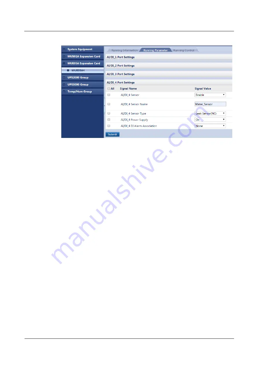
Figure 5-12


Adding a water sensor 


----End 

5.2.3.5 Adding a Device Connected to a DI Port on the GPRS Expansion 
Card 

Prerequisites 


You have obtained the ECC500 IP address as well as the user name and password for 
WebUI login. 


You have prepared a PC which is in the same IP address segment as the ECC500 and 
connected the PC to the ECC500 over a switch. 

Context 


The following example describes how to add a diesel generator (DG) or mains status 
monitoring device connected to a DI port on the GPRS expansion card. 


After a DG or mains status monitoring cable is connected to the ECC500, set port 
parameters on the ECC500 WebUI. After the setting, you can check whether the DG or 
mains power supply is active on the ECC500 WebUI. 


The DG and mains status monitoring cables are respectively connected to the DI_1 and 
DI_2 ports on the MUC01A1 card (GPRS expansion card) in the ECC500 by default. If 
they are connected to other ports, set the port parameters using the following method. 

Procedure 

Step 1


Log in to the ECC500 WebUI. 

Step 2


Choose 

Monitoring

 > 

MUC01A1

 > 

Running Parameter

 > 

DI_1 Port Settings

Step 3


Set 

DI_1 Sensor

 to 

Enable

Step 4


Click 

Submit

Summary of Contents for ECC500

Page 1: ...ECC500 V600R001C03 User Manual Issue 05 Date 2020 03 16 HUAWEI TECHNOLOGIES CO LTD ...

Page 2: ...tomer All or part of the products services and features described in this document may not be within the purchase scope or the usage scope Unless otherwise specified in the contract all statements information and recommendations in this document are provided AS IS without warranties guarantees or representations of any kind either express or implied The information in this document is subject to c...

Page 3: ...ptions or service interruptions if they are misused These commands are not provided in this document If you need these commands contact Huawei technical support The screen snapshots in this document are for reference only The actual screen prevails Intended Audience This document is intended for Marketing engineers Technical support engineers System engineers Hardware installation engineers Commis...

Page 4: ...jury equipment damage and environment deterioration Change History Changes between document issues are cumulative The latest document issue contains all the changes made in earlier issues Issue 05 2020 03 16 Updated section Commissioning Preparations Incorporated the content in ECC500 V600R001C03 Hardware Cable Connection and Commissioning Guide into ECC500 V600R001C03 User Manual Issue 04 2019 12...

Page 5: ... 17 3 2 1 Main Control Module 17 3 2 2 Power Module 19 3 2 3 RS485 Communication Card 20 3 2 4 AI DI Expansion Card 22 3 2 5 Independent Deployment AI DI Unit 24 4 Installation and Commissioning 27 4 1 Installation and Commissioning Flowchart 27 4 2 Installing Devices 27 4 2 1 Installing a Rack mounted ECC500 27 4 2 2 Installing a Wall mounted ECC500 29 4 2 3 Optional Installing a Rack mounted Ind...

Page 6: ...5 13 Connecting the Fan Monitoring Cable 41 4 4 Commissioning Devices 42 4 4 1 Setting the ENR1DETA MODULE T H Sensor Device Address 44 4 4 2 Setting the WS332M2 5 T H Sensor Device Address 45 4 4 3 Setting the UPS2000 G A Device Address 45 4 4 4 Setting the UPS2000 G B Device Address 46 4 4 5 Setting the UPS5000 E Device Address 47 4 4 6 Setting the UL33 UPS Device Address 48 4 4 7 Setting the Ne...

Page 7: ...ms Historical Alarms and Historical Data 89 6 Maintenance and Troubleshooting 90 6 1 Routine Maintenance 90 6 2 Alarm Reference 90 6 2 1 Alarm Reference for the RS485 Communication Card 91 6 2 1 1 MUS02A_Board Not Exist 91 6 2 1 2 MUS02A_COM4 Voltage Low Alarm 91 6 2 2 Alarm Reference for the AI DI Expansion Card 92 6 2 2 1 MUE05A_Board Not Exist 92 6 2 2 2 MUE05A_AIDI_1 DI Alarm 93 6 2 2 3 MUE05A...

Page 8: ...arms 115 7 12 How Should I Link an AI DI Alarm to a DO Port 116 7 13 How Can I Change the System Site Name 118 7 14 How Can I Change the Device Name 119 7 15 How Can I Set Temperature and Humidity Alarm Thresholds for a T H Sensor 120 7 16 How Can I Change Fan Alarm Thresholds and Reset a Fan 121 7 17 How Can I Delete a Device Failing in Communication or Restart the ECC500 123 7 18 How Can I View ...

Page 9: ...ing the equipment The safety instructions in this document are only supplements to local laws and regulations Huawei will not be liable for any consequences of the following circumstances Operation beyond the conditions specified in this document Installation or use in environments which are not specified in relevant international or national standards Unauthorized modifications to the product or ...

Page 10: ...erminal measure the contact point voltage and ensure that there is no risk of electric shock After installing the equipment remove idle packing materials such as cartons foam plastics and cable ties from the equipment area In the case of a fire immediately leave the building or the equipment area and turn on the fire alarm bell or make an emergency call Do not enter the building on fire in any cas...

Page 11: ...e exposed to an outdoor environment for a long period of time Before operations ensure that the equipment is firmly secured to the floor or other solid objects such as a wall or an installation rack Do not use water to clean electrical components inside or outside of a cabinet Do not change the structure or installation sequence of equipment without permission Do not touch a running fan with your ...

Page 12: ...es and degree of various potential hazards in equipment installation operation maintenance Trained personnel personnel who are technically trained have required experience are aware of possible hazards on themselves in certain operations and are able to take protective measures to minimize the hazards on themselves and other people Operators operation personnel who may come in contact with the equ...

Page 13: ...stance of at least 30 mm exists between the cables and heat generating components or areas This prevents damage to the insulation layer of the cables Do not route cables behind the air intake and exhaust vents of the equipment Ensure that cables meet the VW 1 flame spread rating requirements Bind cables of the same type together When routing cables of different types ensure that they are at least ...

Page 14: ...prevent fire due to high temperature ensure that the ventilation vents or heat dissipation system are not blocked when the equipment is running Install the equipment in an area far away from liquids Do not install it under areas prone to condensation such as under water pipes and air exhaust vents or areas prone to water leakage such as air conditioner vents ventilation vents or feeder windows of ...

Page 15: ...nnel Carry the operation machinery and tools properly to prevent them from falling off and causing injuries Personnel involving working at heights are not allowed to throw objects from the height to the ground or vice versa Objects should be transported by tough slings hanging baskets highline trolleys or cranes Ensure that guard rails and warning signs are set at the edges and openings of the are...

Page 16: ...m its load bearing capacity Do not overload it Ensure that the ladder is securely positioned The recommended angle for a ladder against the floor is 75 degrees as shown in the following figure An angle rule can be used to measure the angle Ensure that the wider end of the ladder is at the bottom or protective measures have been taken at the bottom to prevent the ladder from sliding When climbing a...

Page 17: ...s When moving the equipment by hand wear protective gloves to prevent injuries Move or lift the equipment by holding its handles or lower edges Do not hold the handles of modules such as power supply units fans and boards that are installed in the equipment because they cannot support the weight of the equipment Avoid scratching the cabinet surface or damaging cabinet components and cables during ...

Page 18: ...e power supply to equipment which will interrupt services Exercise caution when manually shutting down the UPS inverter for transferring to bypass mode or when adjusting the UPS output voltage level or frequency Doing so may affect the power supply to equipment Exercise caution when setting battery parameters Incorrect settings will affect the power supply and battery lifespan ...

Page 19: ...a complete solution for working environment and security management It collects manages and analyzes operating information of power and environment monitoring devices and reports alarms for them 2 2 Features Hardware Functions The ECC500 supports AC inputs of 100 V to 240 V 50 Hz or 60 Hz and can be used worldwide RS485 Communication Card AI DI Expansion Card and independent deployment AI DI unit ...

Page 20: ...ntrol module rolls back to the source version if the upgrade fails You can re upgrade functional modules if upgrades fail The ECC500 supports simple network management protocol SNMP northbound interfaces that are compliant with SNMP v1 v2c and v3 The ECC500 allows you to download the management information base MIB files The ECC500 allows you to download or upload configuration files for system ba...

Page 21: ...a transmission The ECC500 provides SNMP northbound interfaces for connecting to a third party NMS to query data and report alarms The ECC500 used for transparent data transmission can connect to diverse devices complying with the Modbus protocol and providing dry contacts For the devices that can be connected see the monitoring device list for the project Local Management If the ECC500 is used for...

Page 22: ...Issue 05 2020 03 16 Copyright Huawei Technologies Co Ltd 14 Figure 2 3 Networking for local management For the devices that can be connected to and managed by the ECC500 used for local management see B Devices Managed by the ECC500 ...

Page 23: ...a maximum of four RS485 expansion cards and AI DI expansion cards can be configured Independent deployment AI DI units can only be connected to COM4 and COM5 ports on RS485 expansion cards in slots 3 and 4 A maximum of two independent deployment AI DI units can be connected to each port and the Independent Deployment AI DI Unit addresses can only be 1 or 2 If two RS485 expansion cards are configur...

Page 24: ...s of 12 V actual range 12 8 15 V 400 mA to devices such as Independent Deployment AI DI Units and intelligent T H sensors The power supply status indicators for the power output ports are steady green when they provide power outputs and are off when they supply no power AI DI expansion card MUE05A Mandatory 1 PCS Provides four AI DI ports with 12 V DC outputs to sensors such as smoke sensors and w...

Page 25: ...WA Mandatory 1 PCS Converts the AC input of 100 V to 240 V into two DC outputs of 53 5 V and 15 V Provides the overcurrent output overvoltage and overheat protection Supports natural cooling of rectifiers 3 2 Port 3 2 1 Main Control Module The main control module provides the LCD for querying setting and controlling local parameters Figure 3 2 shows ports on the front panel of the main control boa...

Page 26: ...ns The LCD displays parameters that for you to configure and query in real time by pressing the four buttons on the panel Table 3 3 describes the buttons Table 3 3 Button description Button Name Description or Arrow button Allows you to view menu items and set the value of a menu item Return button Returns to the previous menu without saving the settings Confirm button Enters the main menu from th...

Page 27: ...85 RS232 port for connecting northbound equipment reserved COM1 and COM2 RS485 interfaces for connecting southbound equipment reserved USB Reserved This port is protected by a security protection mechanism 3 2 2 Power Module Figure 3 3 shows the port on the front panel of the power module Figure 3 3 Front panel of the power module Table 3 5 describes the performance specifications of the power mod...

Page 28: ... ambient temperature and humidity sensor Figure 3 4 shows ports on the front panel of the RS485 communication card Figure 3 4 Front panel of the RS485 communication card 1 COM1 port 2 COM2 port 3 COM3 port 4 COM4 12V port 5 COM5 12V port 6 Indicators Table 3 6 describes indicators on the front panel of the RS485 communication card Table 3 6 Description of indicators on the front panel of the RS485...

Page 29: ... port properly provides the 12 V DC output COM5 12V Off The port provides no 12 V DC output Table 3 7 describes ports on the front panel of the RS485 communication card Table 3 7 Description of ports on the front panel of the RS485 communication card Silk Screen Port Description COM1 COM2 and COM3 Connect to intelligent equipment such as the PDU8000 UPS and cooling equipment 1 A 2 B 4 A 5 B COM4 1...

Page 30: ...o an RS485 port and connects to an RS485 communications card one COM port connects to only one RS232 device The recommended COM port is COM1 COM2 or COM3 The internal circuit design of the RS485 communication card allows its COM port to support two wire RS485 and four wire RS422 eliminating the need to cascade cables as shown in Figure 3 5 Figure 3 5 Compatibility of the RS485 interfaces 3 2 4 AI ...

Page 31: ... panel of theAI DI expansion card Silk Screen Color Meaning Status Description PWR Green Power indicator Steady on The power supply is normal Off The AI DI expansion card is faulty or has no DC input RUN Green Run indicator Blinking 1 second on and 1 second off The AI DI expansion card is communicating with the main control module properly Blinking 0 125 second on and 0 125 second off The AI DI ex...

Page 32: ...wise the port will be invalid Sensors including 4 mA to 20 mA sensors door status sensors water sensors and smoke sensors provide data for the ports The power supply of each AI DI port can be separately controlled Each port provides a maximum of 14 6 V 54 mA output power 3 2 5 Independent Deployment AI DI Unit Independent deployment AI DI units can only be connected to COM4 and COM5 ports on RS485...

Page 33: ...iption of indicators on the front panel of the Independent Deployment AI DI Unit Silk Screen Color Meaning Status Description PWR Green Power indicator Steady on The power supply is normal Off The AI DI expansion card is faulty or has no DC input RUN Green Run indicator Blinking 1 second on and 1 second off The Independent Deployment AI DI Unit is communicating with the main control module properl...

Page 34: ...ent based smoke sensors and water sensors dry contact signals and NTC signals Pin definition 3 12 V DC 54 mA 6 D 7 D 8 GND The Independent Deployment AI DI Unit is configured with a 4 bit DIP switch Set toggle switches 1 to 3 to configure the address of the Independent Deployment AI DI Unit and set toggle switch 4 to enable or disable the resistance for the RS485 port Table 3 12 describes the mapp...

Page 35: ...the flowchart for installing and commissioning the ECC500 Figure 4 1 ECC500 installation and commissioning flowchart 4 2 Installing Devices 4 2 1 Installing a Rack mounted ECC500 Prerequisites The installation position has been determined The following tools are available Phillips screwdriver flat head screwdriver and rubber mallet Context A flat head screwdriver can be used as a floating nut moun...

Page 36: ...nting holes in the posts of the rack as shown in Figure 4 2 Figure 4 2 Installing a floating nut Ensure that the floating nuts on both sides are on the same horizontal line Step 2 Place the ECC500 on the correct guide rails in the cabinet Step 3 Secure the ECC500 in the cabinet by tightening the M6 screws clockwise on the right and left mounting ears as shown by 2 in Figure 4 3 Figure 4 3 Installi...

Page 37: ...ECC500 at the installation position on the wall and mark the mounting ear hole positions using a marker Step 3 Drill holes at the marked installation position hole spacing 52 mm x 472 mm on the wall using a hammer drill and install four M8 expansion bolts into the holes Step 4 Install the ECC500 at the expansion bolts on the wall and ensure that the rear panel of the ECC500 is flush with the wall ...

Page 38: ...floating nut mounting bar Procedure Step 1 Use a floating nut mounting bar to install floating nuts one on each site into the mounting holes in the posts of the rack as shown in Figure 4 5 Figure 4 5 Installing floating nuts Ensure that the floating nuts on both sides are on the same horizontal line Step 2 Install long mounting ears on the Independent Deployment AI DI Unit Step 3 Secure the Indepe...

Page 39: ... the wall and mark the mounting ear hole positions using a marker Step 3 Drill holes at the marked installation position hole spacing 52 mm x 205 mm on the wall using a hammer drill and install four M8 expansion bolts into the holes Step 4 Install the Independent Deployment AI DI Unit at the expansion bolts on the wall and ensure that the rear panel of the module is flush with the wall Step 5 Tigh...

Page 40: ...I DI Unit Figure 4 8 Connecting ground cables 4 3 2 Connecting to an IP Network Figure 4 9 shows the cable connection between the ECC500 and an IP network Figure 4 9 Connecting to an IP network 4 3 3 Connecting Monitoring Cables All AI DI and RS485 ports on expansion cards of the ECC500 are connected to monitoring components using standard Ethernet cables with RJ45 connectors as shown in Figure 4 ...

Page 41: ...gure 4 10 Connecting monitoring cables Connect an audible and visual alarm to the ECC500 using the delivered adapter 4 3 4 Connecting Power Cables The power module of the ECC500 is connected to the external power supply using a power cable Figure 4 11 shows the cable connection Figure 4 11 Connecting a power cable ...

Page 42: ...4 3 5 1 Connecting Cables to Intelligent Equipment and Sensors Figure 4 12 shows how to connect cables between the ECC500 and sensors Figure 4 12 Connecting cables to sensors 4 3 5 2 Connecting the ENR1DETA MODULE T H Sensor Monitoring Cable Context When connecting a T H sensor to the ECC500 perform the following steps to prepare a special monitoring cable ...

Page 43: ... 4 13 Figure 4 13 Preparing an RJ45 connector unit mm Step 2 Prepare an RJ12 connector on the other end of the cable as shown in Figure 4 14 Figure 4 14 Preparing an RJ12 connector unit mm Step 3 Plug the RJ45 connector to an RS485 port with 12 V power supply in the ECC500 and the RJ12 connector to the RS485 port in the T H sensor End 4 3 5 3 Connecting the WS332M2 5 T H Sensor Monitoring Cable Co...

Page 44: ...rt in the T H sensor End 4 3 5 4 Connecting the UPS2000 G B Monitoring Cable Context When connecting a UPS2000 G B to the ECC500 perform the following steps to prepare a special monitoring cable The cable connection method described in the section applies to cable connections from the ports of the RS485 expansion card in the ECC500 to devices UPS2000 G B V200R001 is used and equipped with an LCD s...

Page 45: ... UPS2000 G A Monitoring Cable Context The cable connection method described in the section applies to cable connections from the ports of the RS485 expansion card in the ECC500 to devices UPS2000 G A V100R001 is used and equipped with an LCD screen as shown in Figure 4 17 Figure 4 17 LCD screen display Procedure Step 1 Prepare RJ45 connectors on both ends of a network cable as shown in Figure 4 13...

Page 46: ...rt Context The cable connection method described in the section applies to cable connections from the ports of the RS485 expansion card in the ECC500 to devices Procedure Step 1 Prepare RJ45 connectors on both ends of a network cable as shown in Figure 4 13 Step 2 Plug one RJ45 connector to an RS485 port in the ECC500 collector and the other one to the RS485 port in the adapter Step 3 Connect the ...

Page 47: ...f a network cable as shown in Figure 4 13 Step 2 Plug one RJ45 connector to an RS485 port in the ECC500 and the other one to the RS485 port in the PDU8000 End 4 3 5 11 Connecting the ABB OTM ATS Monitoring Cable Context Before the PDU8000 configured with an ABB OTM ATS is delivered the wiring terminal block in the PDU8000 is connected to the RS485 port on the rear of the ABB OTM ATS You only need ...

Page 48: ...lometer Monitoring Cable Context Before the power distribution cabinet PDU8000 configured with the PD510 coulometer is delivered the wiring terminal block in the PDU8000 has connected to the RS485 port on the rear of the PD510 coulometer You only need to connect the monitoring cable to the wiring terminal block in the PDU8000 Locate the RS485 port on the wiring terminal block by using either of th...

Page 49: ...000 In the example shown in Figure 4 19 PDU8000 wiring terminal 1 is RS485 and wiring terminal 2 is RS485 Figure 4 19 PDU8000 wiring terminal Step 3 Plug the RJ45 connector to an RS485 port in the ECC500 End 4 3 5 13 Connecting the Fan Monitoring Cable Context The fan can be connected only to the COM1 port of the main control module in the ECC500 Procedure Step 1 Prepare RJ45 connectors on both en...

Page 50: ...Table 4 1 Indicator description Module Normal Indicator Status Main control module The run indicator blinks on for 1s and then off for 1s The alarm indicator is off RS485 expansion card AI DI expansion card and Independent Deployment AI DI Unit The PWR indicator is steady on The RUN indicator blinks on for 1s and then off for 1s The ALM indicator is off Setting ECC500 Communications Parameters LCD...

Page 51: ...echnologies Co Ltd 43 Figure 4 20 Setting communications parameters Querying Information LCD You can view active alarms over the LCD as shown in Figure 4 21 Figure 4 21 Viewing active alarms Basic Settings LCD Figure 4 22 shows how to set the LCD contrast Figure 4 22 Setting the LCD contrast ...

Page 52: ...sword Figure 4 24 shows how to restore ECC500 factory settings over the LCD Restoring factory settings will restore the ECC500 parameters to their factory settings Perform this operation with caution Figure 4 24 Restoring factory settings 4 4 1 Setting the ENR1DETA MODULE T H Sensor Device Address Procedure Step 1 Operate the DIP switch on the T H sensor to set the device address for the sensor ...

Page 53: ...h 6 Toggle Switch 7 Toggle Switch 8 1 ON OFF OFF OFF OFF OFF OFF OFF 2 OFF ON OFF OFF OFF OFF OFF OFF 3 ON ON OFF OFF OFF OFF OFF OFF 4 OFF OFF ON OFF OFF OFF OFF OFF End 4 4 2 Setting the WS332M2 5 T H Sensor Device Address Procedure Step 1 Hold down SET on the display panel of the T H sensor for 2 seconds Step 2 When Add is displayed set the device address by pressing and End 4 4 3 Setting the U...

Page 54: ...Switch 4 Toggle Switch 5 Toggle Switch 6 Toggle Switch 7 Toggle Switch 8 1 OFF ON ON ON ON ON ON ON 2 ON OFF ON ON ON ON ON ON 3 OFF OFF ON ON ON ON ON ON 4 ON ON OFF ON ON ON ON ON End 4 4 4 Setting the UPS2000 G B Device Address Context UPS2000 G B V200R001 is used and equipped with an LCD screen as shown in Figure 4 26 Figure 4 26 LCD screen display Procedure Step 1 Operate the DIP switch S1 on...

Page 55: ...en powered on Procedure Step 1 Tap Settings on the UPS5000 E home screen Step 2 Enter the administrator user name and password and tap on the screen The preset user name and password for the UPS5000 E are respectively Admin and 000001 To ensure access security change the password upon first use Step 3 Tap Communication Step 4 Set RS485 address and RS485 baud rate Table 4 6 Parameter description Pa...

Page 56: ...n the NetCol5000 A home screen Step 2 Enter the administrator user name and password and tap on the screen The preset user name and password for the NetCol5000 A are respectively Admin and 000001 To ensure access security change the password upon first use Step 3 Tap Com Settings Step 4 Set Com address and Baud Rate Table 4 7 Parameter description Parameter Setting Com address Indicates the device...

Page 57: ...3 Tap Com Settings Step 4 Set Com address and Baud Rate Table 4 8 Parameter description Parameter Setting Com address Indicates the device address planned for the NetCol8000 A The addresses of devices connected to the same collector port must be unique When creating a NetCol8000 A on the ECC500 WebUI enter the value in Device address Baud Rate Retain the default value 9600 The DataBit StopBit and ...

Page 58: ... be unique When creating a PDU8000 on the ECC500 WebUI enter this value in Equipment Address The DataBit StopBit and Parity for the PDU8000 cannot be set on the WebUI Their default values are 8 1 and None respectively End 4 4 10 Setting the ABB OTM ATS Device Address Prerequisites You have obtained the device address assigned to the ABB OTM ATS The ABB OTM ATS has been powered on Procedure Step 1 ...

Page 59: ...password The preset password is 1000 To protect the access security change the password after logging in to the coulometer for the first time Step 2 Press ENTER Step 3 SyS is displayed Then press ENTER Step 4 Set communications parameters Table 4 10 Parameter description Parameter Description Addr Indicates the device address planned for the PD510 coulometer The devices with the same address canno...

Page 60: ...ou to View active alarms View the running status of the system Set system parameters select a language and set communications parameters Set basic parameters such as the date time and LCD contrast Change the password Restore factory settings 5 1 1 LCD Menu Hierarchy Figure 5 1 shows the LCD main menu hierarchy Figure 5 1 LCD menu hierarchy A password is required for access to System Control and Ba...

Page 61: ...ons The figure is for reference only Selecting a Language After powering on the ECC500 select English by pressing or as shown in Figure 5 2 and then press to enter the standby screen Figure 5 2 Screen for selecting a display language After accessing the operating system you can change the display language by performing the steps shown in Figure 5 3 Figure 5 3 Setting the language Setting the Date ...

Page 62: ...ion 5 2 WebUI To ensure secure data transmission the ECC500 transmits encrypted data over the Secure Sockets Layer SSL protocol to the WebUI which allows you to View system status and current alarm information Set system parameters Add devices If the ECC northbound interface is connected by a NetEco devices connected to the COM port on the ECC500 do not need to be added on the ECC WebUI such as th...

Page 63: ...dress SNMP and site parameters Query e label version and fault information Add and view video links 5 2 1 Commissioning Preparations Table 5 1 lists the data required for commissioning Table 5 1 Data preparation Device Parameter Value Remarks ECC500 IP address Preset value 192 168 1 168 To ensure access security change the IP address upon first login For details see 7 4 How Can I Change the ECC500...

Page 64: ...xplorer 8 as an example Open the Internet Explorer choose Tools Internet Options click the Advanced tab and select Use TLS1 1 and Use TLS1 2 5 2 2 Adding a T H Sensor Prerequisites A T H sensor is connected to the ECC500 The ECC500 has been powered on You have obtained the ECC500 IP address as well as the user name and password for WebUI login You have prepared a PC which is in the same IP address...

Page 65: ...ting system is used perform this operation based on actual conditions Step 3 Set User Name and Password and click Log In The WebUI login page is displayed as shown in Figure 5 7 Figure 5 7 ECC500 WebUI login page Step 4 Choose Home Equipment Manage Step 5 Select Temp Hum from the Equipment Type drop down list box and set device parameters as shown in Figure 5 8 Table 2 2 describes the setting meth...

Page 66: ...port Table 5 2 T H sensor parameters Parameter Setting Communication Board Slot Select 3 from the drop down list box Communication Board COM Select 5 from the drop down list box Equipment Address In this example set Equipment Address to 1 Set the actual device address of the T H sensor during operations Timeout The default timeout interval is 2s Set the parameter to the required value Step 6 Click...

Page 67: ...ther port set the port parameters using the following method A smoke sensor can be automatically identified After it is connected to an AI DI port on the ECC500 The sensor type is automatically identified and displayed in AI DI_1 Sensor Type on the ECC500 WebUI Procedure Step 1 Log in to the ECC500 WebUI Step 2 Choose Monitoring MUE05A Expansion Card MUE05A4 Running Parameter AI DI_1 Port Settings...

Page 68: ...of the ECC500 by default To connect the SPD to another port set the port parameters using the following method An SPD is a normally closed NC dry contact device The normal signal status is NC and the alarm signal status is normally open NO Procedure Step 1 Log in to the ECC500 WebUI Step 2 Choose Monitoring MUE05A Expansion Card MUE05A4 Running Parameter AI DI_2 Port Settings Step 3 Set AI DI_2 Se...

Page 69: ...onnected to the AI DI_3 port on the MUE05A4 of the ECC500 by default To connect the door status sensor to another port set the port parameters using the following method Procedure Step 1 Log in to the ECC500 WebUI Step 2 Choose Monitoring MUE05A Expansion Card MUE05A4 Running Parameter AI DI_3 Port Settings Step 3 Set AI DI_3 Sensor to Enable Step 4 Click Submit Step 5 Set AI DI_3 Sensor Name for ...

Page 70: ...other port set the port parameters using the following method A water sensor can be automatically identified After it is connected to an AI DI port on the ECC500 The sensor type is automatically identified and displayed in AI DI_4 Sensor Type on the ECC500 WebUI Procedure Step 1 Log in to the ECC500 WebUI Step 2 Choose Monitoring MUE05A Expansion Card MUE05A4 Running Parameter AI DI_4 Port Setting...

Page 71: ... DG or mains status monitoring device connected to a DI port on the GPRS expansion card After a DG or mains status monitoring cable is connected to the ECC500 set port parameters on the ECC500 WebUI After the setting you can check whether the DG or mains power supply is active on the ECC500 WebUI The DG and mains status monitoring cables are respectively connected to the DI_1 and DI_2 ports on the...

Page 72: ...y Step 7 Click Submit Figure 5 13 shows the configured page Figure 5 13 Adding a DG status monitoring device Step 8 Choose Monitoring MUC01A1 Running Parameter DI_2 Port Settings Step 9 Set DI_2 Sensor to Enable Step 10 Click Submit Step 11 Set DI_2 DI Level to NO Step 12 Set DI_2 Sensor Name for example to Mains_power_supply Step 13 Click Submit Figure 5 14 shows the configured page ...

Page 73: ...stem Settings Alarm Parameters Step 15 Select MUC01A from the drop down list box and click Confirm Step 16 Set DI_1 Alarm and DI_2 Alarm to Enable Step 17 Click Submit as shown in Figure 5 15 Figure 5 15 Masking DG or mains status alarms End Follow up Procedure After setting the parameters choose Monitoring MUC01A1 Running Parameter to view the DG and mains status ...

Page 74: ... and connected the PC to the ECC500 over a switch Context After a UPS2000 G is connected to the ECC500 add the UPS2000 G on the ECC500 WebUI Procedure Step 1 Log in to the ECC500 WebUI Step 2 Choose Home Equipment Manage Step 3 Select UPS from the Equipment Type drop down list box and set device parameters as shown in Figure 5 16 Table 5 3 describes the setting methods Figure 5 16 Adding a UPS2000...

Page 75: ...tion fails check whether the settings are consistent with the device parameters 5 2 4 2 Adding a UPS5000 E Prerequisites A UPS5000 E is connected to the ECC500 The UPS5000 E and ECC500 have been powered on You have obtained the ECC500 IP address as well as the user name and password for WebUI login You have prepared a PC which is in the same IP address segment as the ECC500 and connected the PC to...

Page 76: ...onnected port Communication Board COM Select 2 from the drop down list box NOTE The setting example indicates that the UPS5000 E is connected to the COM2 port of the RS485 card in slot 3 of the ECC500 If the UPS5000 E is connected to another port set the number of the connected port Equipment Address In this example set Equipment Address to 1 Set the actual device address of the UPS5000 E during o...

Page 77: ...he ECC500 add the EA800 UPS on the ECC500 WebUI Procedure Step 1 Log in to the ECC500 WebUI Step 2 Choose Home Equipment Manage Step 3 Select EA800UPS from the Equipment Type drop down list box and set device parameters as shown in Figure 5 18 Table 5 5 describes the setting methods Figure 5 18 Adding the EA800 UPS Table 5 5 EA800 UPS parameters Parameter Setting Communication Board Slot Select 3 ...

Page 78: ...heck whether the settings are consistent with the device parameters 5 2 4 4 Adding a UL33 UPS Prerequisites A UL33 UPS is connected to the ECC500 The UL33 UPS and ECC500 have been powered on You have obtained the ECC500 IP address as well as the user name and password for WebUI login You have prepared a PC which is in the same IP address segment as the ECC500 and connected the PC to the ECC500 ove...

Page 79: ...nnected port Communication Board COM Select 2 from the drop down list box NOTE The setting example indicates that the UL33 UPS is connected to the COM2 port of the RS485 card in slot 3 of the ECC500 If the UL33 UPS is connected to another port set the number of the connected port Equipment Address In this example set Equipment Address to 1 Set the actual device address of the UL33 UPS during opera...

Page 80: ...500 over a switch Context After a NetCol5000 A is connected to the ECC500 add the NetCol5000 A on the ECC500 WebUI Procedure Step 1 Log in to the ECC500 WebUI Step 2 Choose Home Equipment Manage Step 3 Select NetCol from the Equipment Type drop down list box and set device parameters as shown in Figure 5 20 Table 5 7 describes the setting methods Figure 5 20 Adding a NetCol5000 A Table 5 7 NetCol5...

Page 81: ...meter to the required value Step 4 Click Add Equipment End Follow up Procedure If the device addition fails check whether the settings are consistent with the device parameters 5 2 6 Adding a NetCol8000 A Prerequisites A NetCol8000 A is connected to the ECC500 The NetCol8000 A and ECC500 have been powered on You have obtained the ECC500 IP address as well as the user name and password for WebUI lo...

Page 82: ...connected port Communication Board COM Select 5 from the drop down list box NOTE The setting example indicates that the NetCol8000 A is connected to the COM5 port of the RS485 card in slot 3 of the ECC500 If the NetCol8000 A is connected to another port set the number of the connected port Equipment Address In this example set Equipment Address to 1 Set the actual device address of the NetCol8000 ...

Page 83: ...DU8000 is connected to the ECC500 add the PDU8000 on the ECC500 WebUI Procedure Step 1 Log in to the ECC500 WebUI Step 2 Choose Home Equipment Manage Step 3 Select PDU8000 from the Equipment Type drop down list box and set device parameters as shown in Figure 5 22 Table 5 9 describes the setting methods Figure 5 22 Adding a PDU8000 Table 5 9 PDU8000 parameters Parameter Setting Communication Board...

Page 84: ...ick Add Equipment End Follow up Procedure If the device addition fails check whether the settings are consistent with the device parameters 5 2 8 Adding an ABB OTM ATS Prerequisites An ATS is connected to the ECC500 The ATS and ECC500 have been powered on You have obtained the ECC500 IP address as well as the user name and password for WebUI login You have prepared a PC which is in the same IP add...

Page 85: ...nected port Communication Board COM Select 5 from the drop down list box NOTE The setting example indicates that the ATS is connected to the COM5 port of the RS485 card in slot 3 of the ECC500 If the ATS is connected to another port set the number of the connected port Equipment Address In this example set Equipment Address to 1 Set the actual device address of the ATS during operations Timeout Th...

Page 86: ...r is connected to the ECC500 add the PD510 coulometer on the ECC500 WebUI Procedure Step 1 Log in to the ECC500 WebUI Step 2 Choose Home Equipment Manage Step 3 Select PD510 from the Equipment Type drop down list box and set device parameters as shown in Figure 5 24 Table 5 11 describes the setting methods Figure 5 24 Adding a PD510 coulometer Table 5 11 PD510 coulometer parameters Parameter Setti...

Page 87: ... parameters 5 2 10 Adding a Networked Device Prerequisites A networked device is connected to the ECC500 over a switch The device and ECC500 have been powered on You have obtained the IP address of the networked device You have obtained the ECC500 IP address as well as the user name and password for WebUI login You have prepared a PC which is in the same IP address segment as the ECC500 and connec...

Page 88: ...er operating system is used perform this operation based on actual conditions Step 3 Set User Name and Password and click Log In The WebUI login page is displayed as shown in Figure 5 26 Figure 5 26 ECC500 WebUI login page Step 4 Choose Monitoring System Equipment Running Parameter Step 5 Set Enable online detection to Enable Step 6 Click Submit Step 7 Set Device address and Device name Set Device...

Page 89: ...d the camera IP address You have obtained the ECC500 IP address as well as the user name and password for WebUI login You have prepared a PC which is in the same IP address segment as the ECC500 and connected the PC to the ECC500 over a switch Context After a video link is added the camera IP address is recorded in the ECC500 WebUI and you can open the linked camera page from the ECC500 WebUI A ma...

Page 90: ...Video name Enter the name assigned to the camera Video address Enter the URL of the camera After entering the information in Video Info Input click View to display the linked camera page Step 4 Click Add to list Step 5 Select the video link to be submitted and click Submit Step 6 Click View in Video Info List to display the linked camera page Figure 5 29 Viewing camera information End ...

Page 91: ...nnected the PC to the ECC500 over a switch Context Set SNMPv3 parameters before connecting the ECC500 to the NMS These parameters are needed for setting up the ECC500 on the NMS The default values of SNMP Version and SNMP Port Number are SNMPv3 and 161 respectively You change the SNMP version and port number using the following method Procedure Step 1 Log in to the ECC500 WebUI Step 2 Choose Syste...

Page 92: ... system requirements Note that the MD5 SHA Password and DES AES Password must be different Record the settings MD5 and DES are insecure SHA and AES are recommended and they are chosen in the following example Step 7 After setting the parameters click Confirm Figure 5 32 Setting SNMPv3 parameters_03 Step 8 Click Add in SNMP Trap as shown in Figure 5 33 Figure 5 33 Setting SNMPv3 parameters_04 Step ...

Page 93: ...nnected the PC to the ECC500 over a switch You have applied for a security certificate and its key and copied them to a PC Context If the ECC500 collector needs to communicate with an upstream network management system install the security authentication certificate by following instructions in this section You need to apply to an organization authorized by the customer for a security certificate ...

Page 94: ...encrypted select If an encrypted private key is imported enter the password for decryption and enter Key password and Confirm key password Step 9 Click Submit as shown in Figure 5 35 Figure 5 35 Uploading a security certificate_01 Step 10 Click Browse behind Select a root certificate Step 11 Select the root security certificate to be imported from the PC and click Upload Step 12 Click Submit as sh...

Page 95: ... authentication to Enable and click Submit 3 Set New Password and Confirm password and then click Change Password Reset the challenge certification password only when necessary because the resetting will disconnect the connection between the ECC500 collector and the NMS Step 3 Optional To restore the challenge certification password to the factory default click Reset password End 5 2 15 Optional E...

Page 96: ...he ECC500 WebUI Step 2 Choose Maintenance Configuration File as shown in Figure 5 37 Figure 5 37 Exporting a configuration file Step 3 Export a configuration file 1 Click Back Up Current Settings 2 Save the current configuration file to the PC Step 4 Import a configuration file 1 Log in to the WebUI of the ECC500 to which a configuration file is to be imported Choose Maintenance Configuration File...

Page 97: ...p 2 Click Monitoring select the device to be viewed and select Running Information to view the running parameters of the device Step 3 Choose Home Active Alarms to view ECC500 to view active alarms of devices boards and dry contacts connected to the ECC500 collector Step 4 Choose Query to view historical alarms and data including performance data and operation logs 1 To view historical alarms choo...

Page 98: ...tor is blinking 1 second on and 1 second off For details see 6 3 Troubleshooting Semi annual The Alarm indicator is off Indicator status of the RS485 expansion card AI DI expansion card and Independent Deployment AI DI Unit The PWR indicator is steady on The RUN indicator is blinking 1 second on and 1 second off The ALM indicator is off 6 2 Alarm Reference This section describes the alarm referenc...

Page 99: ...m Severity Alarm Type 22630 Set to Major by default Equipment alarm Impact on the System After this alarm is generated the WebUI stops updating parameter values of undetected equipment and fails to send configuration signals Maintain the equipment immediately Possible Causes The board is not securely inserted The board is removed The board is faulty Procedure Step 1 Securely insert the board and t...

Page 100: ...Procedure Step 1 Replace the faulty board Step 2 Replace the faulty power module Step 3 Reduce the power consumption of the RS485 equipment or provide extra power supply to the RS485 equipment Step 4 Check the cable connections between loads and the port End Clearing This alarm is cleared when the output voltage of the COM4 port exceeds the alarm clearance threshold 6 2 2 Alarm Reference for the A...

Page 101: ...moved The board is faulty Procedure Step 1 Securely insert the board and tighten the screws Step 2 Replace the faulty board End Clearing This alarm is cleared when the board is securely inserted into the subrack and the communication between the board and the ECC500 resumes 6 2 2 2 MUE05A_AIDI_1 DI Alarm Description This alarm is generated when the normally open NO dry contacts are closed or the n...

Page 102: ...iption This alarm is generated when the values reported by the sensors exceed the allowed ranges or the sensors are not connected Attribute Alarm ID Alarm Severity Alarm Type 22636 Set to Major by default Equipment alarm Impact on the System After this alarm is generated values reported by sensors are displayed as invalid and the sensors need to be maintained immediately Possible Causes Values rep...

Page 103: ...ment keeps running properly but the sensors need to be maintained immediately Possible Causes Onsite signal volumes exceed the upper alarm thresholds The alarm thresholds are inappropriate The sensors are not securely connected The sensors are faulty Procedure Step 1 Check whether the onsite signal volumes exceed the upper alarm thresholds Step 2 Check that the alarm thresholds are appropriate Ste...

Page 104: ... sensors are faulty Procedure Step 1 Check whether the onsite signal volumes are below the lower alarm thresholds Step 2 Check that the alarm thresholds are appropriate Step 3 Check that sensor cables are properly connected Step 4 Replace the faulty sensors End Clearing This alarm is cleared when the values reported by the sensors are within the allowed ranges 6 2 2 6 MUE05A_AIDI_1 Voltage Low Ala...

Page 105: ...pes of sensors detected by AIDI_1 do not match the specified types or sensor cables are incorrectly connected Attribute Alarm ID Alarm Severity Alarm Type 22698 Set to Major by default Equipment alarm Impact on the System After this alarm is generated the system keeps running but sensors are abnormal Possible Causes Sensor cables are incorrectly connected Types of the sensors do not match the spec...

Page 106: ...nected the power supply is abnormal or the board is faulty Attribute Alarm ID Alarm Severity Alarm Type 22656 Set to Major by default Equipment alarm Impact on the System After this alarm is generated the WebUI stops updating parameter values of undetected equipment and fails to send configuration signals Maintain the equipment immediately Possible Causes Cables are not securely connected The powe...

Page 107: ...cted Possible Causes The power supply to the RS485 board is faulty Cables are not securely connected The power supply to the Independent Deployment AI DI Unit is faulty Procedure Step 1 Replace the faulty RS485 board or power module Step 2 Check that cables are properly connected Step 3 Replace the Independent Deployment AI DI Unit End Clearing This alarm is cleared when the power voltage exceeds ...

Page 108: ...ep 2 Step 2 Check whether the ECC500 communications board is faulty If yes repair or replace the communications board If no go to Step 3 Step 3 Check whether the device is faulty If yes repair the device If no contact Huawei technical support End 6 2 5 Network Device Connect Fail Description This alarm is generated when a networked device is disconnected from the ECC500 Attribute Alarm ID Alarm Se...

Page 109: ...ep 3 If no reset the communications parameters Step 3 Check whether the network is proper If yes go to Step 4 If no repair the network Step 4 Check whether the networked device is faulty If yes repair the networked device If no contact Huawei technical support End 6 2 6 ECC500 Network Fault Description This alarm is generated when the ECC500 is disconnected from the network Attribute Alarm ID Alar...

Page 110: ...s in good contact with the ECC500 runs properly and has normal power input The Run indicator is blinking fast 0 125s on and 0 125s off indicating that communication between the main control module and the host is abnormal Check that the communications cable between the main control module and the host is properly connected The Alarm indicator is on indicating that there is a critical or major alar...

Page 111: ...xpansion card or AI DI expansion card is powered on the first time the ALM indicator is on One minute later the RUN indicator blinks fast indicating that the board is in poor contact Reinstall the board For details about how to view alarm information see 7 11 How Can I Handle Alarms 6 4 Parts Replacement Context This section describes how to replace parts of the ECC500 Before replacing parts ensur...

Page 112: ... 2 Loosen the two captive screws on the panel of the old module counterclockwise by using an M3 screwdriver Step 3 Hold the handle with both hands and pull out the module as shown in Figure 6 1 Figure 6 1 Removing an old module Step 4 Grasp the handle of the new module and put the module into the correct slot in the ECC500 subrack Step 5 Push the new module into the subrack until their front panel...

Page 113: ...nd two smart cooling products connect to each port For other requirements contact Huawei technical support Independently deployed Independent Deployment AI DI Units and temperature and humidity T H sensors need to be powered by the ECC500 collector A maximum of two independently deployed Independent Deployment AI DI Units and eight T H sensors can connect to each port The distance between the ECC5...

Page 114: ...key you obtained to the PC Context Install a network security certificate if a security certificate problem message is displayed when you attempt to log in to the ECC500 WebUI You need to apply to an organization authorized by the customer for a network security certificate and its key with the ECC500 IP address or domain name This section describes how to import the certificate and key Procedure ...

Page 115: ... 7 6 How Can I Change the ECC500 LUI Password You have installed hardware for the ECC500 and powered it on You have obtained the IP address subnet mask and default gateway information planned for the ECC500 Context A unified IP address 192 168 1 168 is configured for all ECC500s before delivery Reconfigure an IP address for the ECC500 as required to ensure normal communication with a server Proced...

Page 116: ...ich is in the same IP address segment as the ECC500 and connected the PC to the ECC500 over a switch You have obtained the IP address subnet mask and default gateway information planned for the ECC500 The network code that the ECC500 does not support is used as the IP address or gateway address Check the network configuration of the ECC500 and ensure that its network code is different from the gat...

Page 117: ...her operating system is used perform this operation based on actual conditions Step 3 Set User Name and Password and click Log In The login page is displayed as shown in Figure 7 3 Figure 7 3 ECC500 login page Step 4 Choose System Settings IP Address Settings Change the IP address subnet mask and default gateway for the ECC500 based on the planned parameters as shown in Figure 7 4 ...

Page 118: ...ord Prerequisites You have obtained the password used for ECC500 LUI login Procedure Step 1 Press on the ECC500 LUI Step 2 Press to move the cursor to Basic Settings and press Step 3 Enter the password press and to modify the value and press Step 4 Press to move the cursor to Change Password and press Remember the new password because it is necessary for ECC500 commissioning and maintenance ...

Page 119: ...the PC to the ECC500 over a switch You have obtained the ECC500 IP address as well as the user name and password for WebUI login Procedure Step 1 Log in to the ECC500 WebUI Step 2 Choose Maintenance User Management Step 3 Select the user you want to modify as shown in Figure 7 5 Figure 7 5 Changing the ECC500 password_01 Step 4 Click Modify Remember the new password because it is necessary for ECC...

Page 120: ...nd Operator user groups are optional on the user management page and they have different operation rights Administrator Users in this group have all the rights including user management as well as browsing and modifying all parameters in the system Engineer Users in this group have all the rights except system upgrade and fault information export Operator Users in this group have all the rights ex...

Page 121: ...tenance User Management Step 3 Click Add as shown in Figure 7 7 Figure 7 7 Adding an ECC500 user _01 Step 4 Set User Name Password and Confirm password select an option from the Authority drop down list box and click Confirm as shown in Figure 7 8 Figure 7 8 Adding an ECC500 user _02 Step 5 Enter the password that you have logged in to the system and click Submit End ...

Page 122: ... 7 9 Setting the date and time Step 3 Set the date and time and click Submit End 7 10 How Can I Enable or Disable an Alarm and Set the Alarm Severity Prerequisites You have obtained the ECC500 IP address as well as the user name and password for WebUI login You have prepared a PC which is in the same IP address segment as the ECC500 and connected the PC to the ECC500 over a switch Context Enable o...

Page 123: ...10 Figure 7 10 Enabling or disabling an alarm and setting the alarm severity Step 5 Click Submit End 7 11 How Can I Handle Alarms Prerequisites You have obtained the ECC500 IP address as well as the user name and password for WebUI login You have prepared a PC which is in the same IP address segment as the ECC500 and connected the PC to the ECC500 over a switch Procedure Step 1 Log in to the ECC50...

Page 124: ...w up Procedure Choose Query Historical Alarm and view historical alarms 7 12 How Should I Link an AI DI Alarm to a DO Port Context After an alarm is linked to a DO port the device connected to the DO port will act if the alarm is generated This section describes how to link the alarm generated from the AI DI_1 port on the MUE05A expansion card to the SLOT1_DO port Procedure Step 1 Log in to the EC...

Page 125: ...5A expansion card where the DO port is located is installed in slot 1 of the ECC500 DO_1 represents the DO_1 port on the GPRS expansion card FAN1 represents fan 1 connecting to the ECC500 Figure 7 12 Linking an AI DI alarm to a DO port new page Figure 7 13 Linking an AI DI alarm to a DO port old page Step 4 Choose Monitoring MUE05A Expansion Card MUE05A4 Running Parameter DO Control Step 5 Click D...

Page 126: ...ddress as well as the user name and password for WebUI login You have prepared a PC which is in the same IP address segment as the ECC500 and connected the PC to the ECC500 over a switch Context Site network fault alarms are sent to the specified mobile phone numbers of maintenance engineers through SMS After the system site name is changed the new site name will be displayed in the short message ...

Page 127: ...aintenance engineers can easily locate the fault The names of the following devices can be changed T H sensor UPS2000 G UPS5000 E NetCol5000 A NetCol8000 A PDU8000 and ATS The device names can be changed in the same way The following describes how to change the names of the UPS2000 G and T H sensor Procedure Step 1 Log in to the ECC500 WebUI Step 2 Change the UPS2000 G name 1 Choose Monitoring UPS...

Page 128: ...he ECC500 You have obtained the ECC500 IP address as well as the user name and password for WebUI login You have prepared a PC which is in the same IP address segment as the ECC500 and connected the PC to the ECC500 over a switch Procedure Step 1 Log in to the ECC500 WebUI Step 2 Choose Monitoring Temp Hum Group Temp Hum34001 Running Parameter 34001 in Temp Hum34001 is variable and subject to chan...

Page 129: ...he ECC500 The device and ECC500 have been powered on You have obtained the ECC500 IP address as well as the user name and password for WebUI login You have prepared a PC which is in the same IP address segment as the ECC500 and connected the PC to the ECC500 over a switch Context A fan can be automatically identified After the fan is connected to the ECC500 the fan information is displayed on the ...

Page 130: ...odify parameters using fan 1 as an example Procedure Step 1 Log in to the ECC500 WebUI Step 2 Choose Monitoring FAN Group FAN1 Running Parameter Modify High Temperature Alarm Thres and Low Temperature Alarm Thres Figure 7 19 Changing fan alarm thresholds Step 3 Choose Monitoring FAN Group FAN1 Running Control Set FAN Reset to Yes and click Submit ...

Page 131: ...nnected the PC to the ECC500 over a switch Context If there is no need to use or monitor a device power off the device or disconnect the device from the ECC500 and then delete the device failing in communication on the ECC500 After the device is deleted the device will not report any alarm to the ECC500 Before deleting a device failing in communication ensure that the device contains no other devi...

Page 132: ...nd click Submit End 7 18 How Can I View Performance Data Prerequisites You have obtained the ECC500 IP address as well as the user name and password for WebUI login You have prepared a PC which is in the same IP address segment as the ECC500 and connected the PC to the ECC500 over a switch Procedure Step 1 Log in to the ECC500 WebUI Step 2 Choose Query Performance Data Step 3 Set Equipment Perform...

Page 133: ...ch is in the same IP address segment as the ECC500 and connected the PC to the ECC500 over a switch Procedure Step 1 Log in to the ECC500 WebUI Step 2 Choose Query Operation Logs and view ECC500 operation logs End 7 20 How Can I View the ECC500 Version Information Prerequisites You have obtained the ECC500 IP address as well as the user name and password for WebUI login You have prepared a PC whic...

Page 134: ... You have prepared a PC which is in the same IP address segment as the ECC500 and connected the PC to the ECC500 over a switch Procedure Step 1 Log in to the ECC500 WebUI Step 2 Choose Query Export Data You can export information of four types Historical Alarms Active Alarms Performance Data and Operation Logs Step 3 Select the desired data type for example Historical Alarm and click Export Histor...

Page 135: ...2 Choose Maintenance Fault Information and click Export Fault Information as shown in Figure 7 24 Figure 7 24 Exporting fault information Step 3 Save the exported data to the PC End 7 23 How Can I Restore Factory Settings Prerequisites You have obtained the ECC500 IP address as well as the user name and password for WebUI login You have prepared a PC which is in the same IP address segment as the ...

Page 136: ...nitoring Alarm parameters in System Settings Alarm Parameters Alarm parameters in System Settings SNMP Settings System Site Name in System Settings Site Settings Video Info List parameters in Maintenance View Video Procedure Step 1 Log in to the ECC500 WebUI Step 2 Choose Maintenance Configuration File and click Restore Factory Settings as shown in Figure 7 25 Figure 7 25 Restoring factory setting...

Page 137: ...ndensing Atmospheric pressure 70 106 kPa Altitude When the altitude is less than or equal to 3000 m the device works properly When the altitude is greater than 3000 m the temperature decreases by 1 C for each additional 300 m Moisture resistance Damp heat cyclic 25 55 C 95 RH 48 hours Others Free from explosives electro conductive dust and corrosive air Input voltage Working voltage 100 240 V AC R...

Page 138: ...age temperature 40 C to 70 C Humidity 5 95 RH non condensing Atmospheric pressure 70 106 kPa Altitude When the altitude is less than or equal to 3000 m the device works properly When the altitude is greater than 3000 m the temperature decreases by 1 C for each additional 300 m Moisture resistance Damp heat cyclic 25 55 C 95 RH 48 hours Others Free from explosives electro conductive dust and corros...

Page 139: ...rt Type Device Software Version Device Model UPS2000 G RS485 UPS2000 G A V100R001C10 V100R001C00 UPS2000 G B V200R001C00 UPS5000 E RS485 V100R001C08SPC0 01 PDU8000 RS485 V100R002C00SPC3 00B058SP01 ATS RS485 OTM 400E4C8D220C NetCol5000 A RS485 ACC V100R001C30a NetCol8000 A RS485 ACC V100R001C20SPC5 00b T H sensor RS485 ENR1DETA MODULE WS332M2 5 Smoke sensor Dry contact JTY GD S839 SDLH 94R Water se...

Page 140: ...Type Port Type Device Software Version Device Model WD 900D Door status switch Dry contact M520 Fire alarm Dry contact Audible and visual alarm DO a If the NetCol5000 A does not use ACC V100R001C30 contact Huawei technical support b If the NetCol8000 A does not use ACC V100R001C20SPC500 contact Huawei technical support ...

Page 141: ...hnologies Co Ltd 133 C Acronyms and Abbreviations A AI analog input ATS Automatic Transfer Switch D DI digital input DO digital output E ECC Energy Control Center F FE Fast Ethernet I IP Internet Protocol L LCD Liquid Crystal Display LUI LCD user interface M MIB Management Information Base ...

Page 142: ...User Manual C Acronyms and Abbreviations Issue 05 2020 03 16 Copyright Huawei Technologies Co Ltd 134 P PDU power distribution unit S SNMP Simple Network Management Protocol U UPS uninterruptible power system ...

Reviews: