background image

eA660 Series CPE 
User Guide 

3 Installation 


Issue 06 (2019-04-03) 

Huawei Proprietary and Confidential                                     

Copyright © Huawei Technologies Co., Ltd. 

35 


Figure 3-23


Wall-mounting flowchart 


Procedure 

1


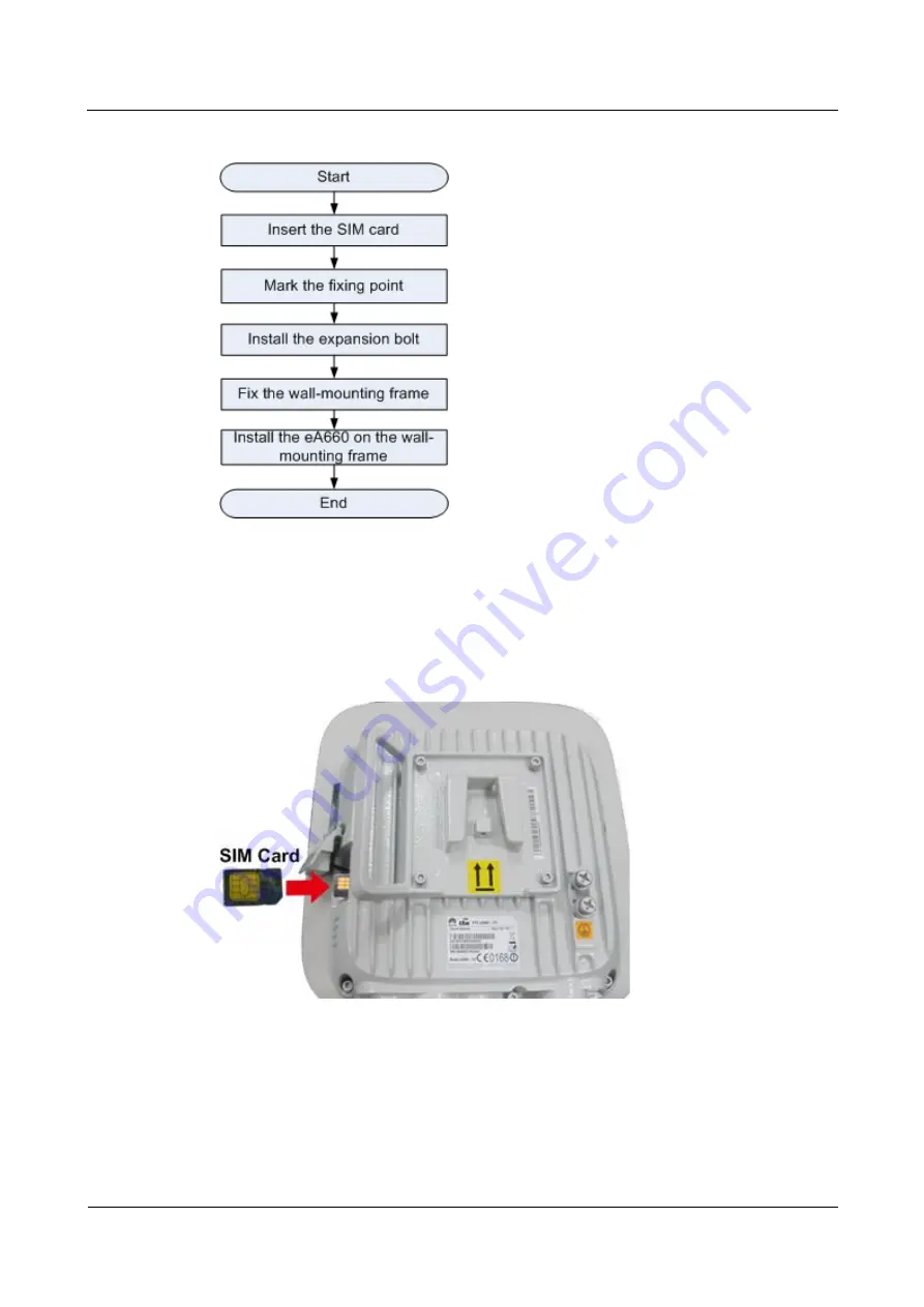
Open the SIM card maintenance window of the eA660 and insert the SIM card, as shown 
in Figure 3-24. 

Figure 3-24


Installing the SIM card 


Figure 3-25 shows the correct installation method. 

Summary of Contents for eA660 Series

Page 1: ...eA660 Series CPE V100R001C00 User Guide Issue 06 Date 2019 04 03 HUAWEI TECHNOLOGIES CO LTD ...

Page 2: ...e customer All or part of the products services and features described in this document may not be within the purchase scope or the usage scope Unless otherwise specified in the contract all statements information and recommendations in this document are provided AS IS without warranties guarantees or representations of any kind either express or implied The information in this document is subject...

Page 3: ... the hardware functions installation configuration operation and maintenance OM of the eA660 series customer premises equipment CPE Product Version Product Name Product Version eA660 118 V100R001C00 eA660 123 V100R001C00 eA660 135 V100R001C00 eA660 137 V100R001C00 eA660 160 V100R001C00 Intended Audience This document is intended for System engineers Product engineers Technical support engineers ...

Page 4: ... 1 PoE Network Cable 17 2 2 2 Ground Cable 18 3 Installation 19 3 1 Site Preparations 19 3 2 Installation Preparation 20 3 3 Installation Procedure 22 3 3 1 Mounting on a Utility Pole Without an Angle Adjusting Component 22 3 3 2 Mounting on a Utility Pole with an Angle Adjusting Component 27 3 3 3 Mounting on the Wall Without an Angle Adjusting Component 34 3 3 4 Mounting on the Wall with an Angl...

Page 5: ... 6 1 What Do I Do If the Web UI Fails to Be Opened 64 6 2 What Do I Do When Power Indicator Is Not Working 64 6 3 What Do I Do When the Data Service Is not Provided 65 6 4 Opening the Web UI Function of the Internet Explorer Is Abnormal 65 7 Privacy and Security 67 7 1 Privacy Policy 67 7 2 Security Maintenance 67 7 3 Performing Default Security Configuration 67 8 Acronyms and Abbreviations 69 ...

Page 6: ...k LAN The eA660 series can connect to external concentrators and Ethernet switches or routers to set up a LAN with multiple computers When terminal devices on the LAN connect to the eA660 using network cables the terminal devices can provide data services Security services The eA660 series supports the firewall and PIN password which protects your computers when you access the Internet Firewall se...

Page 7: ...660 can be deployed independently Figure 1 1 shows an application scenario in which the eA660 is used in private industrial networks The eA660 provides a variety of data services such as LTE TDD wireless routing and converting LTE wireless data into wired Ethernet data and vice versa Figure 1 1 The eA660 deployed in industrial private networks The following example describes how to use the eA660 f...

Page 8: ...nected to a video camera Use a network cable to connect the eA660 to an external device If the eA660 connects to a single device connect the power adapter directly to the eA660 If the eA660 connects to multiple devices connect the power adapter to a Hub or switch and then to the eA660 as shown in Figure 1 3 Figure 1 3 The eA660 connected to multiple devices ...

Page 9: ...800MHz eA660 137 LTE TDD 3600MHz to 3800MHz eA660 160 LTE TDD 2300MHz to 2400MHz LTE TDD 2570MHz to 2620MHz External interface 1 Ethernet interface RJ45 10 100Base TX 1 USB interface 2 External antenna interface N type Female connector 1 SIM card slot LED indicator One POWER indicator One CONNECT indicator One RSSI indicator One HEAT indicator Maximum transmit power 23 dBm 2 Receiving sensitivity ...

Page 10: ...hermometer and hygrometer should be used to monitor and adjust the temperature and humidity 1 4 Antenna Specifications Table 1 2 lists the eA660 antenna s specifications Table 1 2 eA660 LTE antenna specifications Item eA660 118 eA660 123 eA660 135 eA660 137 eA660 160 Band 1785MHz 1805MHz LTE Band 62 2300MHz 2400MHz LTE Band 40 3400MHz 3600MHz LTE Band 42 3600MHz 3800MHz LTE Band 43 3600MHz 3800MHz...

Page 11: ...minutes When the WebUI login password is forgotten contact the device agent or maintenance center to restore factory defaults refer to the AT command manual to restore factory defaults by yourself or contact the device operator to reset the password through TR 069 The WebUI supports remote LTE wireless link and local Ethernet interface or Wi Fi link login Please configure ACL rights based on scena...

Page 12: ...or example 111 is not allowed When the PC UI is unlocked you can run commands to unlock other USB ports or AT commands to map the ports in the following table Port Mapping Name on the Computer Port Usage Port Number HUAWEI Mobile Connect PC UI Interface Used to run AT commands 18 the actual computer port prevails To learn more about AT commands contact your device vendor or the maintenance center ...

Page 13: ...anagement equipment at regular intervals Ensure that the settings for the CPE and central office TR 069 management equipment are the same Otherwise the CPE cannot be managed by the central office TR 069 management equipment MD5 digest authentication is used for connections between the CPE and central office TR 069 management equipment and the authentication complies with TR 069 Amendment 4 When TR...

Page 14: ... Guide 1 Overview Issue 06 2019 04 03 Huawei Proprietary and Confidential Copyright Huawei Technologies Co Ltd 13 The central office TR 069 management equipment will use the SN as the unique identifier for device management ...

Page 15: ...right Huawei Technologies Co Ltd 14 2 Hardware About This Chapter This section describes the hardware and cables of the eA660 2 1 eA660 Hardware This section describes the appearance ports and indicators of the eA660 Appearance Figure 2 1 shows the appearance of the eA660 Figure 2 1 eA660 appearance ...

Page 16: ...aintenance window and indicator Figure 2 2 shows the panel of the eA660 Figure 2 2 Panel of the eA660 Table 2 1 lists the ports of the eA660 Table 2 1 Ports on the eA660 Name Description PoE PoE port LED Indicators SIM card maintenance window Consists of the SIM card slot and USB port A SIM card is inserted into the SIM card slot The USB port is used for internal commissioning Grounding end Connec...

Page 17: ...ntenna or dual antenna installation Indicators of the eA660 are below the SIM card maintenance window and are used to indicate the running status of the eA660 The four indicators from top to bottom are POWER WLINK RSSI and HEAT as shown in Figure 2 3 Figure 2 3 Indicators Table 2 2 describes the indicators of the eA660 Table 2 2 Indicators of the eA660 Identifier Status Description POWER On The po...

Page 18: ...trength is equal to or smaller than 120 dBm HEAT Controlled by the hardware temperature When the hardware temperature is lower than 0 C the hardware is heated and the indicator is on When the hardware temperature is higher than 0 C the indicator is off 2 2 eA660 Cables 2 2 1 PoE Network Cable The power over ethernet PoE network cable is a shielded network cable that is used to connect the PoE port...

Page 19: ...ground cable provides a 6 mm cross section is yellow green and has OT terminals at both ends Figure 2 4 shows the appearance of the ground cable Figure 2 4 Ground cable Technical Specifications Table 2 4 lists the technical specifications of the ground cable Table 2 4 Technical specifications of the ground cable Name Description Color Yellow green Cross section 6 mm Outer diameter 5 1 mm Working t...

Page 20: ...s Keep the site away from high temperature dusty location poisonous gases explosive objects and unstable voltages Keep the site away from any electric substation industrial boiler and heating boiler Keep the site away from any radar station large power radio transmitting station and other interference sources The field strength of interference sources cannot exceed that of unwanted radiation that ...

Page 21: ...the second floor in a building Alternatively mount an eA660 at least 600 mm higher than the record flood stage Requirements for Installation Space To facilitate O M adhere to the following space requirements as shown in Figure 3 1 Figure 3 1 Space requirements for installing an eA660 unit mm Requirements for Operating Environment For details about operating environment requirements see1 3 Hardware...

Page 22: ...n angle of 45 degrees below a separate lightning rod or protection angle of 45 degrees below a surrounding high rise building Ensure that there are no obstacles facing the CPE and enable the CPE to face the base station Installation Tools Table 3 1 lists the tools used for installing the eA660 Table 3 1 Installation tools Hammer drill ESD gloves Vacuum cleaner Heat gun Phillips screwdriver M3 M6 F...

Page 23: ...ng tape Multimeter Marker diameter 10 mm 3 3 Installation Procedure 3 3 1 Mounting on a Utility Pole Without an Angle Adjusting Component Prerequisites The eA660 and mounting components are ready as shown in Figure 3 2 and Table 3 2 Figure 3 2 eA660 and mounting components Table 3 2 Mounting components No Name 1 Mounting frame 2 Hose clamp 3 CPE ...

Page 24: ...igure 3 3 shows the flowchart for mounting the eA660 on a utility pole without an angle adjusting component Figure 3 3 Flowchart for mounting the eA660 on a utility pole without an angle adjusting component Procedure 1 Open the SIM card maintenance window of the eA660 and insert the SIM card as shown in Figure 3 4 Figure 3 4 Installing the SIM card ...

Page 25: ...Figure 3 5 Installation method of the SIM card maintenance window When you install the SIM card maintenance window insert the protrusion into the caging slot to ensure that the SIM card maintenance window is waterproof Do not fasten the screws until the SIM card maintenance window has been correctly installed Step 2 Insert the hose clamp to the wall mounting frame as shown in Figure 3 6 ...

Page 26: ...are hole slightly kink the protruding part and insert it into the other square hole on the front of the unit Step 3 Install the hose clamp with the wall mounting frame on the utility pole and use a M6 hex key to rotate the screw on the hose clamp to adjust the length of the hose clamp until it is correctly connected as shown in Figure 3 7 Figure 3 7 Adjusting the length of the hose clamp If the ho...

Page 27: ... 2019 04 03 Huawei Proprietary and Confidential Copyright Huawei Technologies Co Ltd 26 Figure 3 8 Installing the eA660 on the wall mounting frame Step 5 Tighten the wall mounting frame s screw as shown in Figure 3 9 Figure 3 9 Tightening the screw End ...

Page 28: ...e Adjusting Component Prerequisites The eA660 and mounting components are ready as shown in Figure 3 10 and Table 3 3 Figure 3 10 eA660 and mounting components Table 3 3 Mounting components No Name 1 Angle adjusting component 2 Mounting frame 3 Hose clamp 4 CPE Context Figure 3 11 shows the flowchart for mounting the eA660 to a utility pole equipped with an angle adjusting component ...

Page 29: ...hnologies Co Ltd 28 Figure 3 11 Flowchart of mounting the eA660 to a utility pole equipped with an angle adjusting component Procedure 1 Open the SIM card maintenance window of the eA660 and insert the SIM card as shown in Figure 3 12 Figure 3 12 Installing the SIM card Figure 3 13 shows the correct installation method ...

Page 30: ...method of the SIM card maintenance window When you install the SIM card maintenance window insert the protrusion into the caging slot to ensure that the SIM card maintenance window is waterproof Do not fasten the screws until the SIM card maintenance window has been correctly installed Step 2 Insert the hose clamp to the wall mounting frame as shown in Figure 3 14 ...

Page 31: ... slightly kink the protruding part and insert it into the other square hole on the front of the unit Step 3 Install the hose clamp with the wall mounting frame on the utility pole and use a M6 hex key to rotate the screw on the hose clamp to adjust the length of the hose clamp until it is correctly connected as shown in Figure 3 15 Figure 3 15 Adjusting the length of the hose clamp If the hose cla...

Page 32: ...to loosen the the hex screws on the left of the angle adjusting component and adjust the vertical angle by rotating the front end of the angle adjusting component as shown in Figure 3 17 Then tighten the hex screws Figure 3 17 Adjusting the vertical angle Use the M8 hex key to loosen the the hex screws on the left of the angle adjusting component and adjust the vertical angle by rotating the front...

Page 33: ...The gears of the horizontal angle adjusting part is tightly fit in Consequently the horizontal angle is difficult to adjust When adjusting the horizontal angle after you loosen the hex screws you must lift the front end of the angle adjusting component to separate the gears Step 6 Tighten the angle adjusting component s screw as shown in Figure 3 19 Figure 3 19 Tightening the screw ...

Page 34: ...ght Huawei Technologies Co Ltd 33 Step 7 Fix the eA660 on the angle adjusting component using the dovetail groove as shown in Figure 3 20 Figure 3 20 Installing the eA660 on the angle adjusting component Step 8 Tighten the wall mounting frame s screw as shown in Figure 3 21 Figure 3 21 Tightening the screw ...

Page 35: ...ing on the Wall Without an Angle Adjusting Component Prerequisites The eA660 and mounting components are ready as shown in Figure 3 22 and Table 3 4 Figure 3 22 eA660 and wall mounting components Table 3 4 Wall mounting components No Name 1 Wall mounting screw 2 Mounting frame 3 CPE Context Figure 3 23 shows the flowchart for mounting the CPE on the wall ...

Page 36: ...d Confidential Copyright Huawei Technologies Co Ltd 35 Figure 3 23 Wall mounting flowchart Procedure 1 Open the SIM card maintenance window of the eA660 and insert the SIM card as shown in Figure 3 24 Figure 3 24 Installing the SIM card Figure 3 25 shows the correct installation method ...

Page 37: ... you install the SIM card maintenance window insert the protrusion into the caging slot to ensure that the SIM card maintenance window is waterproof Do not fasten the screws until the SIM card maintenance window has been correctly installed Step 2 Hold the wall mounting frame tightly against the wall use a level to adjust the horizontal position and mark the fixing points with a marker as shown in...

Page 38: ...ints Step 3 Use a drill with 8 mm drill bit to drill holes in the fixing points Then remove the dust from the holes and install the expansion bolts as shown in Figure 3 27 Figure 3 27 Installing the expansion bolt Step 4 Align the two fixing points with the bolts on the wall and tighten the expansion bolt s screw nut to fix the wall mounting frame as shown in Figure 3 28 ...

Page 39: ...logies Co Ltd 38 Figure 3 28 Fixing the wall mounting frame Step 5 Install the ground cable For details see Step 1 in Cable Connection Step 6 Fix eA660 to the wall mount frame using the dovetail groove as shown in Figure 3 29 Figure 3 29 Fixing the CPE Step 7 Tighten the wall mounting frame s screw as shown in Figure 3 30 ...

Page 40: ...awei Proprietary and Confidential Copyright Huawei Technologies Co Ltd 39 Figure 3 30 Tightening the screw End 3 3 4 Mounting on the Wall with an Angle Adjusting Component Prerequisites The eA660 and mounting components are ready as shown in Figure 3 31 and Table 3 5 ...

Page 41: ...Confidential Copyright Huawei Technologies Co Ltd 40 Figure 3 31 eA660 and wall mounting components Table 3 5 Wall mounting components No Name 1 Wall mounting screw 2 Mounting frame 3 Angle adjusting component 4 CPE Context Figure 3 32 shows the flowchart for mounting the CPE on the wall ...

Page 42: ...d Confidential Copyright Huawei Technologies Co Ltd 41 Figure 3 32 Wall mounting flowchart Procedure 1 Open the SIM card maintenance window of the eA660 and insert the SIM card as shown in Figure 3 33 Figure 3 33 Installing the SIM card Figure 3 34 shows the correct installation method ...

Page 43: ... you install the SIM card maintenance window insert the protrusion into the caging slot to ensure that the SIM card maintenance window is waterproof Do not fasten the screws until the SIM card maintenance window has been correctly installed Step 2 Hold the wall mounting frame tightly against the wall use a level to adjust the horizontal position and mark the fixing points with a marker as shown in...

Page 44: ...ints Step 3 Use a drill with 8 mm drill bit to drill holes in the fixing points Then remove the dust from the holes and install the expansion bolts as shown in Figure 3 36 Figure 3 36 Installing the expansion bolt Step 4 Align the two fixing points with the bolts on the wall and tighten the expansion bolt s screw nut to fix the wall mounting frame as shown in Figure 3 37 ...

Page 45: ...he mounting frame using the dovetail groove as shown in Figure 3 38 Figure 3 38 Fixing the angle adjusting component onto the mounting frame Step 6 Adjusting the vertical angle and horizontal angle Use the M8 hex key to loosen the the hex screws on the left of the angle adjusting component and adjust the vertical angle by rotating the front end of the angle adjusting component as shown in Figure 3...

Page 46: ...by rotating the front end of the angle adjusting component as shown in Figure 3 40 Then tighten the hex screws Figure 3 40 Adjusting the horizontal angle The gears of the horizontal angle adjusting part is tightly fit in Consequently the horizontal angle is difficult to adjust When adjusting the horizontal angle after you loosen the hex screws you must lift the front end of the angle adjusting com...

Page 47: ...ght Huawei Technologies Co Ltd 46 Figure 3 41 Tightening the screw Step 8 Fix the eA660 on the angle adjusting component using the dovetail groove as shown in Figure 3 42 Figure 3 42 Installing the eA660 on the angle adjusting component Step 9 Tighten the wall mounting frame s screw as shown in Figure 3 43 ...

Page 48: ...Huawei Proprietary and Confidential Copyright Huawei Technologies Co Ltd 47 Figure 3 43 Tightening the screw End 3 3 5 Cable Connection This section describes the procedure for connecting the eA660 cables Procedure 1 Connect the ground cable as shown in Figure 3 44 ...

Page 49: ...4 03 Huawei Proprietary and Confidential Copyright Huawei Technologies Co Ltd 48 Figure 3 44 Connecting the ground cable Tighten the ground screws and apply antirust paint to it Step 2 Install the crystal connector to PoE network cable as shown in Figure 3 45 ...

Page 50: ...l connector When making PoE network cables follow the international standard EIA TIA568A or EIA TIA568A to arrange the cables Make sure that the two ends of each network cable use the same standard Step 3 Connect the PoE network cable Diassemble the PG head screw cap and air proof block on the PoE port and pass the network cable through them as shown in Figure 3 46 ...

Page 51: ...re 3 46 Passing the network cable through the PG head screw cap and air proof block Connect the network cable to the network adapter and manually rotate the screw cap to ensure that the lock block adheres to the network cable as shown in Figure 3 47 Figure 3 47 Installing the PG head screw cap and air proof block Step 4 Connect the PoE adapter ...

Page 52: ...ng the PoE adapter 1 DATA port connects to the compuer network cable 2 PoE port connects to the PoE network cable End 3 4 Installation Check After you install the eA660 perform a hardware installation check and a power on check Prerequisites The eA660 hardware has been installed Procedure 1 Check whether the eA660 hardware is correctly installed When performing the hardware check for the eA660 che...

Page 53: ...tallation hole on the fixture must be aligned with the one on the expansion bolt In addition the fixture must be tightly and firmly attached to the wall and must not wobble when you shake it When checking the cable connections of the eA660 check the items listed in Table 3 7 in order Table 3 7 Cable connection check of the eA660 No Check Item 1 No cable is short circuited or inversely connected 2 ...

Page 54: ...hecked during eA660 indicator check Table 3 8 Indicator check No Check Item 1 When the eA660 powers on the POWER indicator is on 2 When the eA660 powers on the RSSI indicator is steady on or blinks If the RSSI indicator is off when the eA660 powers on the signal strength is too weak Check the power supply and the angle of the angle adjusting component For details about the indicator status see 2 1...

Page 55: ...tallation of the eA660 is complete The eA660 starts correctly based on default parameters during power on Procedure Step 1 1 Start the IE browser enter http 192 168 1 1 in the address bar and press Enter Connect the eA660 from the near end using the Web management page Use Internet Explorer 7 0 or a later version 2 Log in to the web management page with User name set to default value admin and Pas...

Page 56: ...ing Behind MS are mutually exclusive features On the CPE s web interface select Enable under NAT and click Submit to enable NAT or deselect Enable under NAT and click Submit to enable Routing Behind MS Procedure 4 Log in to the WebUI Please refer to the procedure 4 1 5 Go to Security NAT Settings Deselect Enable under NAT and click Submit to enable Routing Behind MS Figure 4 1 Enabling NAT End 4 3...

Page 57: ...mmunication devices such as devices connected to Wi Fi connected to the CPE require static configuration when obtaining IP addresses Alternatively a DHCP server can be enabled by the peer NE that has a GRE tunnel function to dynamically assign IP addresses to the devices Procedure 6 Log in to the WebUI Please refer to the procedure 4 1 7 Choose LAN Bridge Settings Select the Enable check box next ...

Page 58: ...the CPE cannot obtain IP addresses from the DHCP server until DHCP Relay and Routing Behind MS are both enabled 8 Configure the DHCP server This document demonstrates how the DHCP server can be configured using Windows Server 2003 a On the computer go to Control Panel Management Tools DHCP From the left panel right click Server Options and choose New Scope Wizard Figure 4 3 Server Options New Scop...

Page 59: ...Introduction Issue 06 2019 04 03 Huawei Proprietary and Confidential Copyright Huawei Technologies Co Ltd 58 Figure 4 5 Setting the IP address range d Click Next Figure 4 6 Click Next e Set the lease duration Figure 4 7 Setting the lease duration ...

Page 60: ... I want to configure these settings now and click Next g Set the default gateway Figure 4 8 Setting the default gateway h Click Next on each of the following pages and then click Finish Add a route from the DHCP server to the CPE The next hop is the EPC s IF IP address Figure 4 9 Next hop Add a route from the DHCP server to LAN devices connected to the CPE The next hop is the EPC s IF IP address ...

Page 61: ... Technologies Co Ltd 60 Figure 4 10 Next hop 9 Log in to the WebUI Please refer to the procedure 错误 未找到引用源 10 Go to LAN DHCP Settings DHCP Relay set DHCP Server Address and click Submit Figure 4 11 Setting the DHCP server address 11 Go to Security NAT Settings deselect Enable under NAT and click Submit to enable Routing Behind MS ...

Page 62: ...eA660 Series CPE User Guide 4 Configuration Introduction Issue 06 2019 04 03 Huawei Proprietary and Confidential Copyright Huawei Technologies Co Ltd 61 Figure 1 1 Enabling Routing Behind MS End ...

Page 63: ...nance items and prepare related tools Learning About the Site Information Gather the following site information before going to the eA660 site to perform maintenance Persisting faults and alarms Hardware configuration Natural environment Selecting Maintenance Items Select suitable maintenance items based on the eA660 site conditions Maintenance items must include the following aspects Natural envi...

Page 64: ...dress or domain box Set Packet size and Timeout and select the Enable check box behind Do not Fragment Click Ping Wait until the operation is performed The command output is displayed in the Result box Packet Length indicates the bytes of a sent packet and ranges from 1 to 9 000 bytes Timeout indicates the timeout period of each reply and ranges from 1 to 10 seconds When the CPE does not run prope...

Page 65: ...properly connected Step 2 Check wheather the IP address is entered correctly Step 3 If there is no problem after the above checks try to restart the CPE from the near end Step 4 If the problem persists please contact Huawei technical engineer End 6 2 What Do I Do When Power Indicator Is Not Working Problem Description Power indicator is not working Solution 2 Check whether the PoE cable is correct...

Page 66: ...hether the CPE is powered If the Power indicator presents red light the power supply is provided Step 2 Check whether the SIM card is correctly installed Step 3 Confirm whether the CPE is connected to the network Check whether the RSSI indicator is steady or blinking Step 4 If the problem persists contact local service provider End 6 4 Opening the Web UI Function of the Internet Explorer Is Abnorm...

Page 67: ...eA660 Series CPE User Guide 6 FAQ Issue 06 2019 04 03 Huawei Proprietary and Confidential Copyright Huawei Technologies Co Ltd 66 Step 4 If the problem persists contact local service provider End ...

Page 68: ...ed section in the online help 7 2 Security Maintenance Software components used by this device may report vulnerabilities This device will use the software upgrade mode to fix these issues You can obtain specific software packages from the device agent 7 3 Performing Default Security Configuration After a WebUI login users can check the online help to perform default security configuration Change ...

Page 69: ...4 03 Huawei Proprietary and Confidential Copyright Huawei Technologies Co Ltd 68 The USB port provides maintenance and repair functions and allows you to set device parameters Please keep the password secure to prevent device parameters from being modified or exposed ...

Page 70: ...he eA660 Table 8 1 List of acronyms and abbreviations Acronym Abbreviation Full Name 3GPP 3rd Generation Partnership Project CPE Customer Premises Equipment DHCP Dynamic Host Configuration Protocol GRE Generic Routing Encapsulation LTE Long Term Evolution MAC Media Access Control NAT Network Address Translation PoE Power over Ethernet SIM Subscriber Identity Module TR069 Technical Report 069 URL U...

Reviews: