


User Manual
Aolynk VDR824 ADSL2+ VoIP Broadband Router/
Aolynk VDR824g ADSL2+ VoIP Wireless Broadband Router
2 Installation
8
ect both the ADSL port on the VDR824/824g and the
e
II. Con
To c
:
z
Ethernet port (one among LAN1 through LAN4) of the VDR824/824g.
Connect your PC to the VDR824/824g through the USB ports with a USB cable. It
or the PC without NIC to access the Internet.
z
As shown in Figure 2-1, conn
telephone to a splitter, and then connect the splitter to the telephone jack on th
wall. It allows you to use the telephone when you access the network.
nect to a PC or Ethernet
onnect the VDR824/824g to a PC or Ethernet, two options are available
The Ethernet ports of the VDR824/824g are auto-MDI/MDIX, so you can use the
crossover or straight-through cable to connect your PC, Hub, or switch to the
z
is suitable f
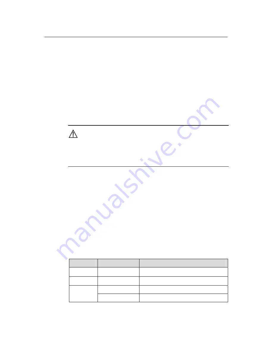
Caution:
T
config
o use the USB port on the VDR824/824g, you must install the USB driver and
ure your PC (refer to section 8 “Appendix - USB Configuration” for detailed
information).
I. Connect to the telephone
II
e telephone with Phone 1 on the rear panel of the
IV
nd of the power adapter to the VDR824/824g and the other end to the
the VDR824/824g.Approximately one minute
after
wer-on, the
f the LEDs on the front
e those listed in
Table 2-2.
Table 2-2
Description of the LED states
Use the telephone cable to connect th
VDR824/824g. If both Phone 1 and Phone 2 are assigned with the registration
accounts, connect another telephone with Phone 2.
. Connect to the power adapter
Attach one e
power outlet. Then turn on the power of
the po
states o
panel should b
LED
State
Description
Power Green
—
Link Green
—
Blinking
Data is being transmitted and received.
Act
ission is present.
OFF
No data transm


