6
Solar inverter
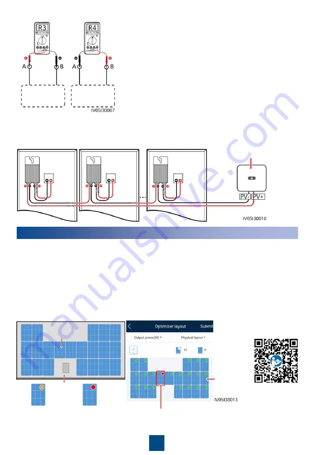
4. Connect cables between the PV string and the solar inverter.
4
Power-On Commissioning
1. The physical layout of the optimizers must be provided so that you can easily locate faulty
optimizers based on the physical layout diagram.
2. The physical layout of the optimizers must be provided to use the optimizer disconnection
detection function. After optimizer disconnection detection is performed, the locating result
can be viewed on the
Optimizer layout
page.
3. Choose
Maintenance > Subdevice management > Auto search
to add an optimizer. Create
a physical layout on the
Physical layout design
screen. For details, see the corresponding
solar inverter quick guide or
FusionSolar App Quick Guide. The solar inverter quick guide is
delivered with the solar inverter. You can scan the QR code to obtain
FusionSolar App Quick
Guide.
Physical
layout
PV rooftop
Location
Faulty optimizer
Disconnection icon
Fault icon
PV string
PV string
a. If R is infinite, an open circuit occurs in the PV string or
the cables are connected to different PV strings. Rectify
the PV string open-circuit fault and correctly group the PV
string cables.
b. If R4 is less than R3, A is the positive cable of the PV
string, and B is the negative cable of the PV string. If R3 is
less than R4, B is the positive cable of the PV string, and A
is the negative cable of the PV string. Attach correct cable
labels.
c. The resistance of each pair of PV module and optimizer is
1 kΩ. The total resistance of a PV string is 1 kΩ times the
number of optimizers. If the total resistance is 10 kΩ, the
number of optimizers in the PV string is 10.
Note: The total resistance of a PV string is (R3 + R4)/2.


