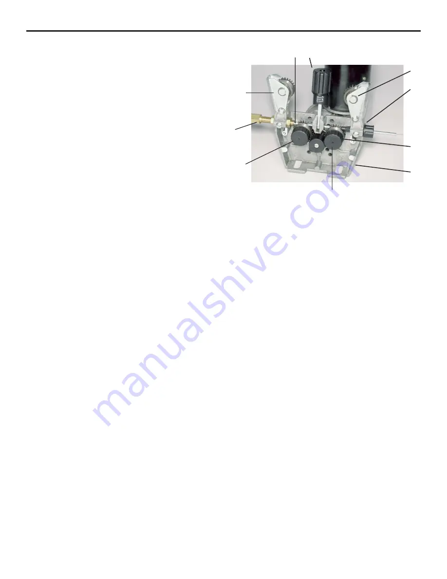
1) Pressure Release Handle/Pressure Adjusting Screw
2) Pressure Roller Assemblies
3) Inlet Wire Guide
4) Drive Roller
5) Guide Tube
6) Adapter Plug
7) Drive Roll Retaining Screw
8) Wire Drive Bracket
5. Remove the contact tip and gas nozzle from the
welding gun. Turn the wire feed rate to 6. Depress
the trigger on the welding gun. At this point, the
wire feed may be inconsistent because the majority of
tension has been removed from the pressure roller.
Slowly tighten the pressure roller adjusting screw
until the wire feeds evenly without slipping. Then
tighten an additional 1/4 turn for steel. No additional
tightening is necessary for aluminum. Using your
fingers like a hand brake on a bicycle, squeeze the
outside edges of the wire spool. You want enough
tension to pull the wire when you put a drag on the
spool, but not so much tension that is requires a large
amount of force to stop the wire from feeding or stall
the motor.
Continue feeding the wire until it appears at the tip of
the welding gun. Check your wire size and install the
correct contact tip. Install the gas nozzle.
6. Bend the welding wire 90-degrees and hold the welding
gun perpendicular to a non-conductive surface (concrete
floor) so that the wire will not feed. While looking at the
wire feed mechanism, momentarily depress the trigger.
The drive roll should slip and act as a clutching mechanism.
If not, the drive roll will push the wire out between the
roller and the guide tube. This is known as "bird nesting."
If bird nesting occurs, the pressure roller has been adjusted
too tightly. When properly adjusted, the drive roll will
slip, and "bird nesting" will never occur.
16
Setting the Pressure on the Pressure Roller
Prior to readjusting the pressure roller, check the following:
1. Are the drive roller and pressure roller clean? If not,
clean with a suitable solvent.
2. Is the liner worn, dirty or kinked, causing a
restriction to the wire feed? (See testing and
changing the liner.) If so, replace the liner.
3. Is the guide tube lined up properly with the drive
roll? If not, align the guide tube.
4. Is the guide tube coming in contact with the drive
rolls? If so, remove the guide tube and shorten it by
grinding.
If all of the above mentioned conditions are in good working
order, then it may be necessary to reset the pressure on the
pressure roller.
1. Loosen the pressure roller adjusting screw (1), pull
the pressure release handle out of the way and lift
the pressure roller assemblies (2) up and out of the
way.
2. Loosen the wire from the spool. Feed the wire into
the inlet wire guide (3), across the drive rolls (4) and
into the guide tube (5). Check to be sure that the
groove in the drive roll is the correct groove for the
wire diameter you are using. Feed the wire until two
or three inches of straight wire protrudes from the
central adapter block.
3. Swing the pressure roller assemblies (2) back into
position, making sure the wire is positioned in the
groove of the drive roll (5). Tighten the pressure
roller adjusting screw just enough to keep the wire in
the groove. DO NOT OVERTIGHTEN!
4. Insert the wire protruding from the central adapter
block into the end of the welding gun. Install the
welding gun on the welding machine.
7
Figure 3
4
8
5
1
3
2
2
6
7
Summary of Contents for MIG 2400
Page 21: ...21 HTP MIG 2400 Wiring Diagram...
Page 22: ...22 Parts List MIG 2400...


