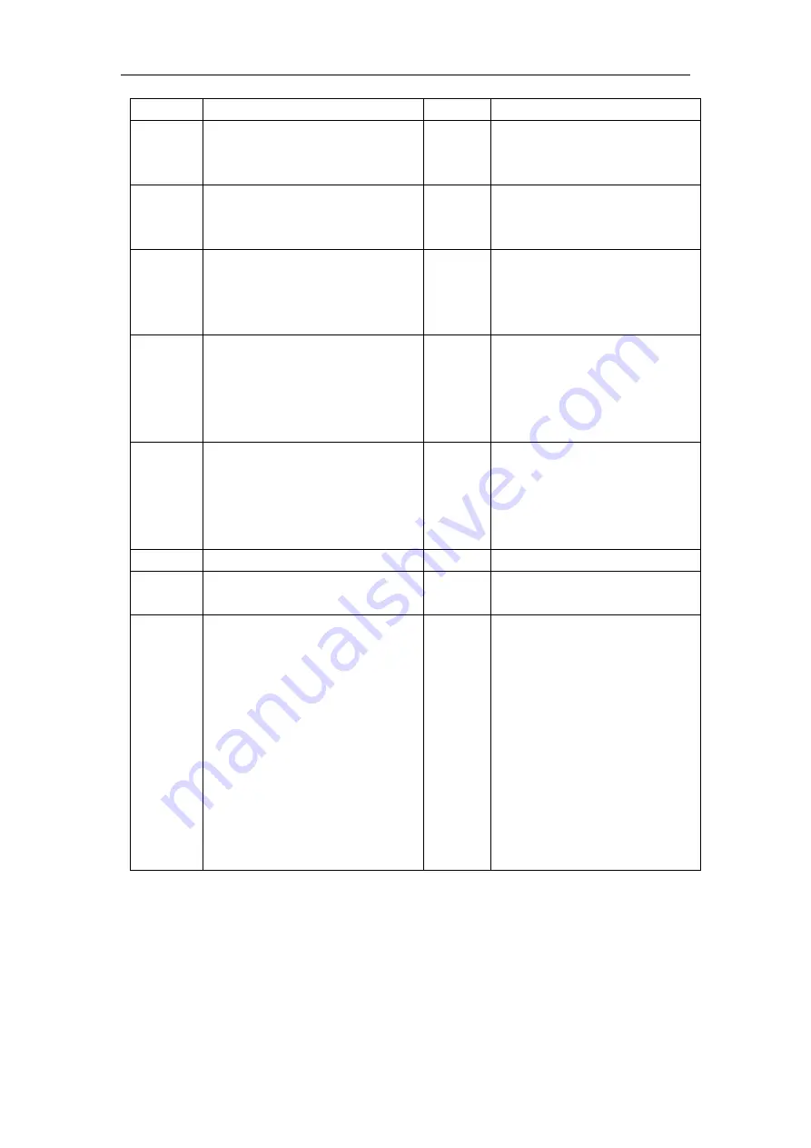
HTP MicroCut 45 DV Operator'S Manual Download Page 14


Light 

Condition 

Display 

Status/Possible Cause 


E01 

Over-Current- Check output 
diodes, main transformer and 
IGBT on the invert board. 

Temp 

On 

E02 

Over-Temperature- Stop 
cutting, allow machine to 
cool down. 


E03 

No system is established- 
Check output diodes, main 
transformer and IGBT on the 
invert board. 

Nozzle 

Repetative flashing rate of 3 
quick circles, then a 1 second 
pause for a 15 second period or 
until torch trigger is pressed 
again, whichever comes first. 

E04 

No pilot arc established 
possibly due to a loss of 
current- Check consumables. 

Nozzle 

Repetative flashing rate of 3 
quick circles, then a 1 second 
pause for a 15 second period or 
until torch trigger is pressed 
again, whichever comes first. 

E05 

Consumables in torch failed 
to separate during pilot arc 
possibly due to being stuck- 
Check consumables. 


E09 

No input power. 

Cup & 
Nozzle 

Repetative flashing rate of one 
quick circle. 

E11 

Torch cup is loose or off. 

Pressure  Repetative flashing rate of 1 

quick circle. 

E13 

E13 means air pressure is out 
of range. H means air 
pressure has exceeded setting 
range. L means air pressure is 
under setting range.In 
Normal/Grid,the setting 
range of air pressure is 4.2-
5.6bar. In Gouging,the 
setting range of air pressure 
is 2.1-3.5bar. In Marking,the 
setting range of air pressure 
is 2.1-3.1bar. 


Summary of Contents for MicroCut 45 DV

Page 1: ...T Read this Owner s Manual Completely before attempting to use this equipment Save this manual and keep it handy for quick reference Pay particular attention to the safety instructions we have provide...

Page 2: ...I...

Page 3: ...er s Warranty Subject to the terms and conditions hereof HTP warrants that all MicroCut 45 DV plasma cutters furnished by HTP are free from defects in workmanship and material as of the time and place...

Page 4: ...ously purchased equipment This warranty is null and void unless the warranty registration is sent to HTP America Inc within fifteen 15 business days from the date of purchase Any express warranty not...

Page 5: ...NS 4 3 3 AIR CONNECTIONS 4 4 OPERATION 4 4 1 LAYOUT OF THE FRONT AND REAR PANEL 5 4 2 FUNCTION INTRODUCTION 6 4 3 CUTTING PREPARATION 9 4 4 CUTTING OPERATION 10 5 MAINTENANCE 11 5 1 CUTTING TORCH MAIN...

Page 6: ...metal being used coatings on the metal and the different processes You must be very careful when cutting any metals which may contain one or more of the following Antimo ny Chromiu m Mercury Berylliu...

Page 7: ...ydrogen gas that is ignited will cause an explosion NOISE Noise can cause permanent hearing loss Plasma processes can cause noise levels to exceed safe limits You must protect your ears from loud nois...

Page 8: ...47 7 03 2 30 6 18 Adjustment range of current A 20 25 20 45 10 25 10 45 Max no load voltage V 230 Duty cycle 40 10 minutes 40 25A145V 50 45A145V 40 25A110V 50 45A118V Note The above parameters are su...

Page 9: ...ur power source for correct voltage before plugging in or connecting the unit 3 3 Air Connections A Connecting Air Supply to Unit Connect the air line to the inlet port of the air filter on the rear p...

Page 10: ...Button Select cutting mode switch between first and second menu 4 Over Heat Alarm When over heating the yellow light will be on 5 Power Light A solid green light indicates the power is on 6 Cutting T...

Page 11: ...ntains air pressure output voltage the recommended length of the cutting torch Cutting current Tips The LCD contains two menus In the first menu the cutting current and the cutting mode can be adjuste...

Page 12: ...ure 4 Figure 5 Figure 6 Figure 7 Grid cutting mode use the encoder to adjust the cutting current press on the function button briefly to switch cutting mode The current range is 20 45A the air pressur...

Page 13: ...8 3 Two different kinds of cutting torches Figure 8 Hand Torch Figure 9 Machine Torch 4 Alarm display...

Page 14: ...zzle Repetative flashing rate of 3 quick circles then a 1 second pause for a 15 second period or until torch trigger is pressed again whichever comes first E05 Consumables in torch failed to separate...

Page 15: ...sure in idle To adjust air pressure press and realease the trigger so air stats flowing Open the side door of cabinate to adjust the air presure 3 After using the machine for a longer period of time t...

Page 16: ...condition a small amount of air vents through the gap between the shield cup and the torch handle Do not attempt to over tighten the shield cup as irreparable damage to internal components may result...

Page 17: ...t torch parts and replace if necessary 2 Air pressure too high or too low adjust to proper pressure 3 Faulty components in unit return for repair C No cutting output trigger pulled power source on air...

Page 18: ...orch shield cup tip starter element and electrode replace as needed 4 Faulty components in unit return for repair or have qualified technician repair G No air flows the power light is on Fan operates...

Page 19: ...14 6 Cutting Guidelines...

Page 20: ...15 7 Consumable Breakdowns Consumable Parts Breakdown Hand Torch Consumable Parts Breakdown Machine Torch...

Page 21: ...otected functional extra low voltage ELV output to prevent shock energy and fire under normal conditions at the machine interface receptacle and under single fault conditions with the machine interfac...

Page 22: ...The connector socket Cable ends Start start plasma Input Normally open Requires dry contact closure to activate 3 4 3 pink 4 brown Transfer start machine motion Output Normally open Dry contact closu...

Page 23: ...18 Note the table below for the shift and scale selection scale selection dial number 20 1 21 1 1 30 1 40 1 50 1 1 OFF ON OFF OFF OFF 2 OFF OFF ON OFF OFF 3 OFF OFF OFF ON OFF 4 OFF OFF OFF OFF ON...

Reviews: