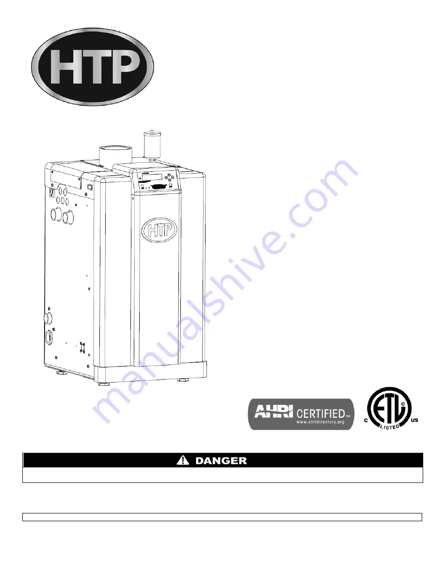
HTP ELP-110 Installation Start-Up Maintenance Parts Download Page 1

120 Braley Rd. P.O. Box 429 

                       East Freetown, MA 02717-0429 

                                      www.htproducts.com 


                     LP-294 REV. 9.2.14 

Elite Plus  

Heating Boiler 


INSTALLATION 


START-UP 


MAINTENANCE 


PARTS 


Models 

ELP-110 / ELP-199 


Heat Exchanger Bears the ASME “H” Stamp 


NOTICE: HTP reserves the right to make product changes or updates without notice and will not be held liable for typographical errors 
in literature. 


NOTE TO CONSUMER: PLEASE KEEP ALL INSTRUCTIONS FOR FUTURE REFERENCE.


This manual must only be used by a qualified heating installer/service technician. Read all instructions in this manual before installing. 
Perform steps in the order given. Failure to comply could result in substantial property damage, severe personal injury, or death. 

Summary of Contents for ELP-110

Page 1: ... to make product changes or updates without notice and will not be held liable for typographical errors in literature NOTE TO CONSUMER PLEASE KEEP ALL INSTRUCTIONS FOR FUTURE REFERENCE This manual must only be used by a qualified heating installer service technician Read all instructions in this manual before installing Perform steps in the order given Failure to comply could result in substantial...

Page 2: ...CINITY OF THIS OR ANY OTHER APPLIANCE WHAT TO DO IF YOU SMELL GAS Do not try to light any appliance Do not touch any electrical switch Do not use any phone in your building Immediately call your gas supplier from a neighbor s phone Follow the gas supplier s instructions If you cannot reach your gas supplier call the fire department Installation and service must be provided by a qualified installer...

Page 3: ...department building official or electrical inspector or others having statutory authority In some circumstances the property owner of his her agent assumes the role and at government installations the commanding officer or departmental official may be the AHJ NOTE HTP Inc reserves the right to modify product technical specifications and components without prior notice FOR THE INSTALLER This manual...

Page 4: ...load based upon the outdoor sensor and the Outdoor Reset Curve sensor response curve in the boiler software This feature may be over ridden as described below in specific installations The boiler control is equipped with an outdoor sensor override for use with building management systems or in cascaded systems for systems with total input of 300 000 BTU hr or greater See statement below for an imp...

Page 5: ...NTIFREEZE SOLUTIONS 27 M ZONING WITH ZONE VALVES 27 N ZONING WITH CIRCULATORS 27 O MULTIPLE BOILERS 27 PART 5 VENTING COMBUSTION AIR AND CONDENSATE REMOVAL 27 A GENERAL 28 B APPROVED MATERIALS FOR EXHAUST VENT AND INTAKE PIPE 28 C REQUIREMENTS FOR INSTALLATION IN CANADA 29 D EXHAUST VENT AND INTAKE PIPE LOCATION 30 E EXHAUST VENT AND INTAKE PIPE SIZING 33 F LONGER VENT RUNS 33 G EXHAUST VENT AND I...

Page 6: ...8 START UP PREPARATION 50 A CHECK CONTROL WATER CHEMISTRY 50 B FREEZE PROTECTION WHEN USED 50 C FILL AND TEST WATER SYSTEM 51 D CHECK FOR GAS LEAKS 51 E CHECK THERMOSTAT CIRCUITS 52 F CONDENSATE REMOVAL 52 G FINAL CHECKS BEFORE STARTING BOILER 52 H CASCADE SYSTEM 53 PART 9 CONTROL AND DISPLAY OVERVIEW 53 A CONTROL OVERVIEW 54 B MENU STRUCTURE 54 C NAVIGATION OF THE DISPLAY 54 D START UP INSTRUCTIO...

Page 7: ... 70 1 LOCKOUT ERROR CODES 70 2 BLOCKING ERROR CODES 71 3 LAMBDACONSTANT LOCKOUT CODES 72 4 LAMBDACONSTANT BLOCKING CODES 72 PART 15 MAINTENANCE 73 A MAINTENANCE PROCEDURES 73 B COMBUSTION CHAMBER COIL CLEANING INSTRUCTIONS FOR BOILER 74 BOILER START UP REPORT 78 MAINTENANCE REPORT 78 MAINTENANCE NOTES 82 HTP CUSTOMER INSTALLATION RECORD FORM 83 PART 1 GENERAL SAFETY INFORMATION A PRECAUTIONS This ...

Page 8: ... to disconnect electrical power before opening boiler cabinet or performing service Failure to do so could result in an electrical shock that could result in property damage serious personal injury or death Due to the low water content of the boiler improper sizing of the boiler with regard to heating system load will result in excessive cycling and accelerated component failure HTP DOES NOT warra...

Page 9: ... hardness Chlorine concentration less than 100 ppm o Using chlorinated fresh water should be acceptable as levels are typically less than 5 ppm o Do not connect the boiler to directly heat swimming pool or spa water o Do not fill boiler or operate with water containing chlorine in excess of 100 ppm NOTE It is recommended to clean the heat exchanger at least once a year to prevent lime scale buildu...

Page 10: ...e display allows the installer to change system parameters and monitor outputs Start Up Learning Behavior When the boiler is first powered on it may have some unsuccessful starts This happens because the boiler control is learning about the system through its sensors Integrated Air Mass Flow Sensor and Modulating Gas Valve An air mass flow sensor is integrated into the boiler fan When the fan rece...

Page 11: ... measurement accuracy and increase overall system efficiency PART 3 PREPARE BOILER LOCATION Carefully consider installation when determining boiler location Please read the entire manual before attempting installation Failure to properly take factors such as boiler venting piping condensate removal and wiring into account before installation could result in wasted time money and possible property ...

Page 12: ...se the system and boiler to freeze and leak Incorrectly sized expansion tank 6 Clean and flush system when reinstalling a boiler NOTE When installing in a zero clearance location it may not be possible to read or view some product labeling It is recommended to make note of the boiler model and serial number Do not mount the boiler to a hollow wall Mount to the studs only Failure to do so will resu...

Page 13: ...ith other appliances Failure to comply with the above could result in substantial property damage severe personal injury or death MINIMUM CLEARANCES FROM COMBUSTIBLE MATERIALS Hot water pipes at least 1 from combustible materials Exhaust vent pipe at least 1 from combustible materials Figure 3 Specifications and Dimensions Drawing MODEL A B C D E F G H J K L SHIPPING WEIGHT ELP 110 19 9 3 27 3 15 ...

Page 14: ...nd intake piping lengths routing and termination method must comply with methods and limits given in the venting section F PREVENT COMBUSTION AIR CONTAMINATION Install intake piping for the boiler as described in the Venting section Do not terminate exhaust in locations that can allow contamination of intake air Ensure that the intake air will not contain any of the contaminants below For example ...

Page 15: ...on venting system properly vents when tested as outlined return doors windows exhaust fans fireplace dampers and any other gas burning appliance to their previous condition of use 7 Any improper operation of the common venting system should be corrected so the installation conforms to the National Fuel Gas Code ANSI Z223 1 When resizing any portion of the common venting system the common venting s...

Page 16: ...oiler is to be connected to a domestic hot water system B RELIEF VALVE Connect discharge piping to a safe disposal location following the guidelines below To avoid water damage or scalding due to relief valve operation Discharge line must be connected to relief valve outlet and run to a safe place of disposal Terminate the discharge line in a manner that will prevent possibility of severe burns or...

Page 17: ...or Always install the system fill connection at the same point as the expansion tank connection to the system 4 Most chilled water systems are piped using a closed type expansion tank DO NOT install automatic air vents on closed type expansion tank systems Air must remain in the system and return to the tank to provide an air cushion An automatic air vent would cause air to leave the system result...

Page 18: ...ude inhibitors that will prevent the glycol from attacking the metallic system components Make certain that the system fluid is checked for correct glycol concentration and inhibitor level The system should be tested at least once a year and as recommended by the glycol solution manufacturer Allowance should be made for expansion of the glycol solution in system piping Example 50 by volume glycol ...

Page 19: ...f all closely spaced tees 4 The minimum pipe size for connecting a SuperStor indirect water heater is 1 5 The minimum pipe size for connecting an Elite Plus is 1 25 6 Circulators are shown with isolation flanges The alternative is standard flanges with full port ball valves Purge valves can be used with circulator flanges as an alternative 7 A mixing valve is recommended if the DHW temperature is ...

Page 20: ...closely spaced tees 4 The minimum pipe size for connecting a SuperStor indirect water heater is 1 5 The minimum pipe size for connecting an Elite Plus is 1 25 6 Circulators are shown with isolation flanges The alternative is standard flanges with full port ball valves Purge valves can be used with circulator flanges as an alternative 7 A mixing valve is recommended if the DHW temperature is set ab...

Page 21: ...ll closely spaced tees 4 The minimum pipe size for connecting a SuperStor indirect water heater is 1 5 The minimum pipe size for connecting an Elite Plus is 1 25 6 Circulators are shown with isolation flanges The alternative is standard flanges with full port ball valves Purge valves can be used with circulator flanges as an alternative 7 A mixing valve is recommended if the DHW temperature is set...

Page 22: ...all closely spaced tees 4 The minimum pipe size for connecting a SuperStor indirect water heater is 1 5 The minimum pipe size for connecting an Elite Plus is 1 25 6 Circulators are shown with isolation flanges The alternative is standard flanges with full port ball valves Purge valves can be used with circulator flanges as an alternative 7 A mixing valve is recommended if the DHW temperature is se...

Page 23: ...ced tees 4 The minimum pipe size for connecting a SuperStor indirect water heater is 1 5 The minimum pipe size for connecting an Elite Plus is 1 25 6 Circulators are shown with isolation flanges The alternative is standard flanges with full port ball valves Purge valves can be used with circulator flanges as an alternative 7 A mixing valve is recommended if the DHW temperature is set above the fac...

Page 24: ...he boiler cannot be drained completely of water without purging the boiler with an air pressure of 15 psi 10 The relief valve and temperature and pressure gauge are included in the boiler accessory kit A pipe discharge line should be installed 6 above the drain in the event of pressure relief The pipe size must be the same size as the relief valve outlet NEVER BLOCK THE OUTLET OF THE SAFETY RELIEF...

Page 25: ...VERED BY WARRANTY Sodium less than 20 mGL Water pH between 6 0 and 8 0 1 Maintain boiler water pH between 6 0 and 8 0 Check with litmus paper or have chemically analyzed by water treatment company 2 If pH differs from above consult local water treatment company for treatment needed Hardness less than 7 grains Consult local water treatment companies for unusually hard water areas above 7 grains har...

Page 26: ...ve 115 F Unions Field supplied Recommended for boiler serviceability DO NOT USE DIELECTRIC UNIONS ONLY BRASS COPPER OR STAINLESS STEEL Pressure relief valve Factory supplied on boiler The pressure relief valve is sized to ASME specifications Storage tank may require additional relief valves depending on local codes MINIMUM PIPE SIZES ELP 110 1 NPT or Copper ELP 199 1 NPT or Copper Table 10 K FILL ...

Page 27: ...ficients M ZONING WITH ZONE VALVES 1 When zoning with zone valves connect the boiler to the system as shown in Piping Details Part 4 Section G The primary secondary piping shown ensures the boiler loop will have sufficient flow It also avoids applying the high head of the boiler circulator to zone valves 2 Connect DHW domestic hot water piping to indirect storage water heater as shown in Piping De...

Page 28: ...ce must be heated or the pipe must be insulated The insulation must have an R value sufficient to prevent freezing of the condensate Improper seating of vent pipe gaskets can cause eventual gasket failure and exhaust gas leakage Ensure the exhaust vent pipe is properly beveled and seated before insertion into the flue adapter Failure to do so could result in property damage severe personal injury ...

Page 29: ...ad bearing devices and must not be used to support exhaust vent piping All vent pipes must be glued properly supported and the exhaust must be pitched a minimum of per foot back to the appliance to allow drainage of condensate Failure to properly support vent piping and follow the information in this statement could result in product damage severe personal injury or death NOTE The use of double wa...

Page 30: ...erminal be above or below the aforementioned equipment unless the 4 foot horizontal distance is maintained J This water heater vent system shall terminate at least 3 feet 0 9 m above any forced air intake located within 10 ft 3 m NOTE This does not apply to the combustion air intake of a direct vent appliance K When venting with a two pipe system maximum distance between exhaust vent and intake pi...

Page 31: ...alizer kit connects to the drain system and contains limestone chips that neutralize the pH level of the water vapor The neutralizer kit should be checked annually and the limestone chips replenished if necessary When replacing the limestone chips take care to ensure chips are no smaller than to avoid blockage in condensate piping refer to Figure 12 for piping of the condensate neutralizer When in...

Page 32: ...o properly reduce vacuum lock in the drain line 2 Plastic pipe should be the only material used for the condensate line Steel brass copper or other materials will be subject to corrosion or deterioration 3 NEVER install condensate lines outside It is very important that the condensate line is not exposed to freezing temperatures or any type of blockage Damages due to frozen or blocked condensate l...

Page 33: ... pipe we will calculate Exhaust Vent Equivalent Length 2x5 10 20 ft Further if the 3 intake pipe has two short 90 o elbows one 45 o elbow and 10 feet of PVC pipe the following calculation applies Intake Pipe Equivalent Length 2x5 3 10 23 ft The Exhaust Vent Equivalent Length Intake Pipe Equivalent Length Total Equivalent Length In this example the Total Equivalent Length is 43 ft c The minimum tot...

Page 34: ...cate vent over public walkways driveways or parking lots Condensate could drip and freeze resulting in a slip hazard or damage to vehicles and machinery 8 Due to potential moisture build up sidewall venting may not be the preferred venting option To save time and cost carefully consider venting installation and location 9 Horizontal lengths of exhaust vent must slope back towards the appliance not...

Page 35: ...orted and the exhaust must be pitched a minimum of per foot back to the boiler to allow drainage of condensate When placing support brackets on vent piping the first bracket must be within 1 foot of the boiler and the balance at 4 foot intervals on the vent pipe Boiler venting must be readily accessible for visual inspection for the first three feet from the boiler Figure 14 Sidewall Venting with ...

Page 36: ...venting ONLY All vent pipes must be glued properly supported and the exhaust must be pitched a minimum of per foot back to the boiler to allow drainage of condensate When placing support brackets on vent piping the first bracket must be within 1 foot of the boiler and the balance at 4 foot intervals on the vent pipe Boiler venting must be readily accessible for visual inspection for the first thre...

Page 37: ...ir intake C Maintain 12 minimum clearance above highest anticipated snow level or grade whichever is greater D Minimum 12 between vents when installing multiple vents E 12 minimum beyond air intake All vent pipes must be glued properly supported and the exhaust must be pitched a minimum of per foot back to the boiler to allow drainage of condensate When placing support brackets on vent piping the ...

Page 38: ...ition L VENTING THROUGH AN EXISTING SYSTEM This boiler may be vented through an existing unused vent system The inner diameter of the existing vent system is utilized for the combustion air source Two methods have been approved for such venting Concentric Venting Through an Existing System and Venting as a Chase Do not install the boiler into a common existing vent with any other appliance This wi...

Page 39: ... result in property damage severe personal injury or death NOTES A For every 1 of overhang the exhaust vent must be located 1 vertical below overhang overhang means top of building structure and not two adjacent walls corner of building B Typical installations require 12 minimum separation between bottom of exhaust outlet and top of air intake C Maintain 12 minimum clearance above highest anticipa...

Page 40: ... the outdoors into the boiler intake connection Unconfined space is space with volume not less than 50 cubic feet per 1 000 Btu hour 4 8 cubic meters per kW of the total input rating of all fuel burning boilers installed in that space Rooms connected directly to this space through openings not furnished with doors are considered part of the space Confined space is space with volume less than 50 cu...

Page 41: ...41 LP 294 REV 9 2 14 Figure 21 1 21 2 NOTE These drawings are meant to demonstrate system venting only The installer is responsible for all equipment and detailing required by local codes ...

Page 42: ...alve must be replaced Never use an open flame match lighter etc to check gas connections B GAS PIPING 1 Run the gas supply line in accordance with all applicable codes 2 Locate and install manual shutoff valves in accordance with state and local requirements 3 In Canada the manual shutoff must be identified by the installing contractor 4 It is important to support gas piping as the boiler is not d...

Page 43: ...upplier qualified installer or service agency to determine correct action that is needed to provide proper gas pressure to the boiler If Gas Pressure is within normal range proceed to Step 6 6 Exit test mode then turn power off and shut off gas supply at the manual gas valve before disconnecting the hose from the gas monitoring device Tighten screw on the pressure tap and turn gas on Check for lea...

Page 44: ...low all local codes To ease future service and maintenance label all wires Wiring errors can cause improper and dangerous operation and result in substantial property damage severe personal injury or death A INSTALLATION MUST COMPLY WITH 1 National Electrical Code and any other national state provincial or local codes or regulations 2 In Canada CSA C22 1 Canadian Electrical Code Part 1 and any loc...

Page 45: ... enter the electrical junction box through the provided knock out holes as shown at right 2 Connect all low voltage field devices to the low voltage terminal strip located in the electrical junction box G THERMOSTAT 1 Connect the room thermostat to the terminals marked THERMOSTAT 14 and 15 in the electrical junction box see Figure 27 Alternately any dry contact closure across these terminals will ...

Page 46: ...nnect the indirect sensor 7250P 325 to the terminals marked DHW SENSOR 10 and 11 shown in Figure 27 in the electrical junction box Take caution to ensure neither of these terminals becomes connected to ground NOTE If sensor wires are located in an area with sources of potential electromagnetic interference EMI the sensor wires should be shielded or the wires routed in a grounded metal conduit If u...

Page 47: ...aster boiler and to be sure that the switch is set to OFF right on the follower boilers and the Interface Module if used so there will be no adverse operation of the communication bus The factory default position is ON M CASCADE MASTER AND FOLLOWER WIRING 1 Wiring for the Cascade Master is accomplished in the same way as a single boiler with one exception The bus communication switch must be flipp...

Page 48: ...48 LP 294 REV 9 2 14 Figure 27 Single or Cascade Master and Cascade Follower Controls ...

Page 49: ...49 LP 294 REV 9 2 14 Figure 28 ...

Page 50: ...company 2 If the pH differs from above consult local water treatment company for treatment needed Hardness less than 7 grains Consult local water treatment companies for unusually hard water areas above 7 grains hardness Chlorine concentration less than 100 ppm 1 Using chlorinated fresh water should be acceptable since drinking water chlorine levels are typically less than 5 ppm 2 Do not connect t...

Page 51: ...d system water temperature increases Operating pressure must never exceed the relief valve pressure setting 4 At initial fill and during boiler startup and testing check system thoroughly for any leaks Repair all leaks before proceeding further 5 Run pumps in System Test Check for leaks Eliminate all system leaks Continual fresh make up water will reduce boiler life Minerals can build up in the he...

Page 52: ...that will be subject to corrosion Plastic PVC or CPVC pipe are the only approved materials A condensate filter if required by local authorities can be made up of lime crystals limestone or phosphate chips that will neutralize the condensate This may be done by the installer or you may purchase a condensate neutralizer from HTP Part 7450P 212 2 The boiler is equipped with a female socket weld fitti...

Page 53: ...ignition device which automatically lights the burner Do not try to light the burner by hand 2 BEFORE OPERATING smell all around the boiler area for gas Be sure to smell next to the floor because some gas is heavier than air and will settle on the floor WHAT TO DO IF YOU SMELL GAS Do not try to light any boiler Do not touch any electric switch do not use any phone in your building Immediately call...

Page 54: ...d user B MENU STRUCTURE After the display has established communication with the main board the installer will be able to use the display to navigate through the boiler menu structure That structure is summarized in Figure 29 Figure 29 Menu Structure C NAVIGATION OF THE DISPLAY The control features a four line LCD display to provide informative messages about the operation of the boiler Six naviga...

Page 55: ...esired amount It is recommended you use the Menu Maps in this manual and the detailed menu instructions printed in this section to help in menu navigation To enter the Installer Menu press the key until you reach the Main Menu Press and hold the ENTER key at one of the Main Screens While holding ENTER press and hold the key After three seconds the Installer Menu will open NOTE The Installer Menu c...

Page 56: ...tains descriptions of Main Screens that can be viewed after the control has connected to the main board If the boiler is in a stand alone system related screens will be found in Section A If the boiler is the cascade master related screens will be found in Section B NOTE The Installer Menu can only be accessed from the Main Screen A STAND ALONE BOILER MAIN SCREENS SCREEN DESCRIPTION STANDBY NO DEM...

Page 57: ...en indicates a temporary blocking error that will reset automatically once the condition is corrected Analyze error at the particular boiler The error description will alternate with Call service number and telephone number of service technician The system temperature is 160 o F Pressing the key brings up the main screen of the master boiler 1 along with the error Pressing returns to the previous ...

Page 58: ... case of a shortcut 0 ohm will be displayed The second line shows the flue gas reading When configured as SWITCH OPEN or CLSD is shown When configured as SENSOR NC means not connected If shortcut 0 ohm will display The final line displays the outdoor temperature reading If an outdoor sensor is not connected NC is shown If shortcut 0 ohm Pressing the or keys allows the User to view more data or ret...

Page 59: ...es if the system pump is ON or OFF Pressing the key allows the User to view more data CASCADE STATUS Boiler 1 xxx 3 xxx 2 xxx 4 xxx This screen shows the modulation range of boilers 1 4 in the cascade system The first boiler in the rotation is marked with an icon on the left The modulation range xxx of each boiler is shown Up to 16 boilers can work in a cascaded system of multiple boilers Pressing...

Page 60: ... Installer to view more data or return to the previous screen BOILER STATUS INST Run time pwrON xxxxxxxdays Service xxxxdays This screen shows the run time in days for total power on and the amount of time until next service as set by the service reminder NOTE Take care not to set the service reminder for a holiday Pressing the or keys allows the Installer to view more data or return to the previo...

Page 61: ...onfirms RESET changes any value back to blank or when blank goes to 0 for faster editing Pressing the or keys allows the Installer to view and or adjust more data or return to the previous screen BOILER CONFIG THERMISTOR TYPE Outdoor NTC 12k All Others NTC 10k This screen allows the installer to switch temperature sensor types from NTC 10k and NTC 12k Options NTC 10k and NTC 12k Pressing the or ke...

Page 62: ...oint The CH mode selected will determine the default Pressing the or keys allows the Installer to view and or adjust more data or return to the previous screen CH SETTINGS Reset Curve Design Outdoor 5 o F Boiler 180 o F Allows the installer to set the upper point for the outdoor reset curve At a specified low outdoor temperature a certain boiler supply temperature must be reached Default is 5 o F ...

Page 63: ...ter or at DHW dedicated boilers ONLY SCREEN DESCRIPTION DHW SETTINGS DHW mode 1 DHW store with sensor Allows Installer to choose between different DHW heating modes 0 No DHW only central heating 1 DHW store with sensor 2 DHW store with thermostat 3 Instant DHW with FlowSW DHW T Sens not used 4 Instant DHW with DHW T Sens not used 5 Instant DHW with DHW T FlowSens not used Factory default is 0 Pres...

Page 64: ...lt is 20 o F Range 0 36 o F Pressing the or keys allows the Installer to view and or adjust more data or return to the previous screen CASCADE SETTINGS Delay Factor for Boiler Offset 2 Time factor is multiplied with next boiler start delay time and determines when the intelligent PID cascading controller becomes active Default is 2 0 Disabled Pressing the or keys allows the Installer to view and o...

Page 65: ... allows the Installer to view and or adjust more data or return to the previous screen LambdaConstant Max Mass Flow Temp Deviation _0K Allows the installer to adjust CO2 at high power Before making any adjustment it is recommended to run the boiler in system test at high power If the CO2 is not within specification use this parameter to adjust while measuring the CO2 The default value is 0 Increas...

Page 66: ...s parameter to set boiler inputs and outputs for a custom installation CH Settings Used to adapt CH central heating for the installation and outdoor reset parameters DHW Settings Used to set DHW domestic hot water for the installation Cascade Settings When set as a cascaded system used to custom adapt the system to the installation only selectable in a cascaded system System Test Enables the insta...

Page 67: ...us screen LambdaConstant Prepurge Actual Speed 3420rpm This is the prepurge fan speed of the last ignition If this speed is not close to the Prepurge Initial Speed displayed in the screen above an MF deviation Error occurs This error signals a significant change in the air inlet flue system or possible heat exchanger blockage Pressing the or keys allows the Installer to view and or adjust more dat...

Page 68: ...ive PID After selecting the CH Mode press the key once to modify the CH Differential CH SETTINGS Central heating Differential 10 o F The CH Differential is the and bandwidth for the CH Setpoint the CH Setpoint is accessed in the User Menu Options 1 The Differential to the setpoint for starting the boiler can be modified here Default 10 o F Range 2 27 o F 2 For CH mode 6 the values are different an...

Page 69: ...etpoint if an indirect sensor is used The factory installed default setpoint is 119 o F Range 104 160 o F Table 40 User Menu Boiler Settings Quick Start Up F CASCADE FOLLOWER MAIN SCREENS To view Cascade Follower Main Screens Press the key to return to the Main Menu SCREEN DESCRIPTION BOILER STANDBY NO DEMAND 160 F This display is visible at single and cascaded boilers BOILER will only appear in c...

Page 70: ...with the letter A In the case of a LOCKOUT error the boiler will not start until a qualified technician has repaired the boiler and pressed the RESET button for more than 1 second IMPORTANT NOTE If you see error messages on your display readout call a technician immediately since the message may indicate a more serious problem will occur soon B USER INTERFACE DISPLAY NOTE If flame goes out after p...

Page 71: ... Internal software error A30 Register error 37 Internal software error A30 CPSM Error 37 Internal software error Table 42 Lockout Error Codes 2 BLOCKING ERROR CODES DISPLAY CODE ERROR INT CODE DESCRIPTION POSSIBLE SOLUTION E31 REFHI TOO LO 50 Internal hardware error Check Field Connection Board on shortcuts otherwise exchange BCU E32 REFHI TOO HI 51 E33 REFLO TOO LO 52 E34 REFLO TOO HI 53 E35 FALS...

Page 72: ...flue gas piping for dirt and condensate A30 C PSM error 37 Internal software error Reset Exchange the BCU A82 Plausi T1_1 error 38 Fan Plausi error Exchange the fan A83 Plausi T1_2 error 39 Fan Plausi error A84 Plausi T2_1 error 40 Fan Plausi error A85 Plausi T3 error 41 Fan Plausi error A86 Plausi T2_1 error 42 Fan Plausi error A87 Plausi T3_1 error 43 Fan Plausi error A30 Register error 44 Inter...

Page 73: ...installer must also inform the owner that a lack of proper care and maintenance of the boiler may result in a hazardous condition BEFORE EACH HEATING SEASON a trained and qualified service technician should perform the inspections as per the boiler inspection and maintenance schedule in the back of the manual Failure to do so could result in death or serious injury Outdoor Sensor 7250P 319 Supply ...

Page 74: ... down the Boiler by using the following steps a Turn off power to the boiler Close the gas valve Turn down the thermostat or disconnect the thermostat connection from the low voltage terminal strip Wait for the boiler to be cool to the touch b Disconnect the condensate piping from the outside connection not from the Boiler side so flow from condensate reservoir can be observed c Disconnect electri...

Page 75: ...robe and combustion blower f Reconnect the wire harness to the combustion blower motor Reconnect the green thermocouple wire to the control board f Turn the gas back on IMPORTANT CHECK ALL CONNECTIONS FOR GAS LEAKS g Restore power to the boiler h Disconnect the White Black Red Blue PWM connector feed to the fan The fan will run at high speed to dry the combustion chamber out It is recommended to w...

Page 76: ...76 LP 294 REV 9 2 14 Figure 32 ...

Page 77: ...77 LP 294 REV 9 2 14 Figure 33 LP 294 B ...

Page 78: ...MAINTENANCE REPORT In unusually dirty or dusty conditions care must be taken to keep boiler cabinet door in place at all times Failure to do so VOIDS WARRANTY Allowing the boiler to operate with a dirty combustion chamber will hurt operation Failure to clean the heat exchanger as needed by the installation location could result in boiler failure property damage personal injury or death Such produc...

Page 79: ...be Clean Check ionization in uA in System Test Part 12 Section F Record high fire and low fire CONDENSATE Neutralizer Check condensate neutralizer Replace if necessary Condensate hose Disconnect condensate hose Clean out dirt Fill with water to level of outlet and re install NOTE Verify the flow of condensate making sure that the hose is properly connected during final inspection GAS Pressure Meas...

Page 80: ...80 LP 294 REV 9 2 14 ...

Page 81: ...81 LP 294 REV 9 2 14 ...

Page 82: ...82 LP 294 REV 9 2 14 MAINTENANCE NOTES ...

Page 83: ...lease also sign this document Customer s Name Installation Address Date of Installation Installer s Code Name Product Serial Number s Comments Installer s Phone Number Signed by Installer Signed by Customer IMPORTANT NOTES In the case that the system has any problems please call the installer If you are unable to make contact or are unhappy with the response please contact your HTP Sales Represent...

Reviews: