


Canada West
855 Park St., Unit 1
Regina, SK S4N 6M1
Canada East
490 Pinebush Rd., Unit 1
Cambridge, ON N1T 0A5
U.S.A.
7229 University Ave NE
Fridley, MN 55432
56 Lightcap Rd.
Pottstown, PA 19464
9760 Mayflower Park Drive,
Suite 110
Carmel, IN 46032
7503 35th St. SE
Calgary, AB T2C 1V3
4655 McDowell Rd. W
Phoenix, AZ 85035
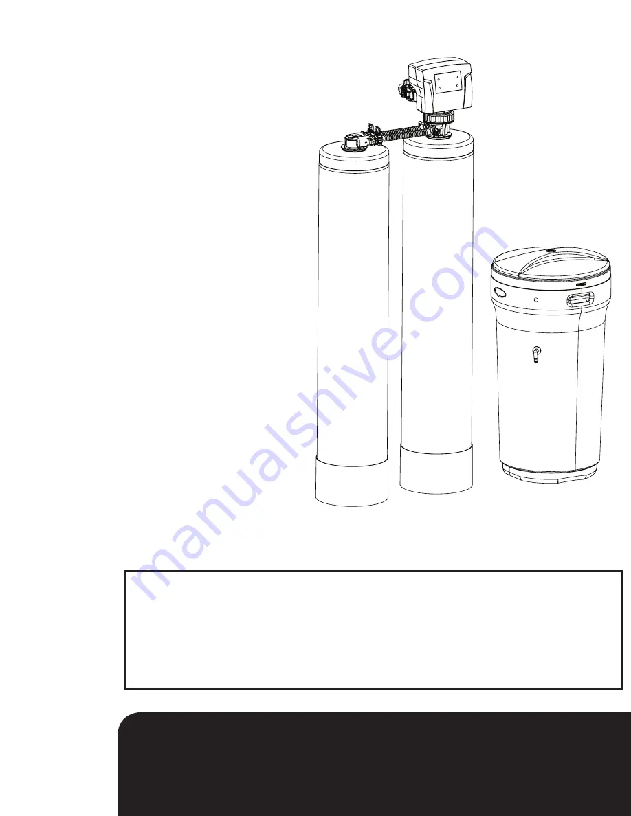
Owners Manual
89 HTO
Hardness Taste and Odor Filter
1.
Read all instructions carefully before operation.
2.
Avoid pinched o-rings during installation by applying NSF certified
lubricant to all seals (provided with install kit).
3.
This system is not intended for treating water that is microbiologically unsafe or of unknown quality
without adequate disinfection before or after the system.
4.
Page 18 of this manual contains important maintenance procedures for the continued proper
operation of your unit. These MUST be performed regularly for your warranty to remain valid.


