background image

17

Connecting RJ-45 Plugs to Cat5e Cable

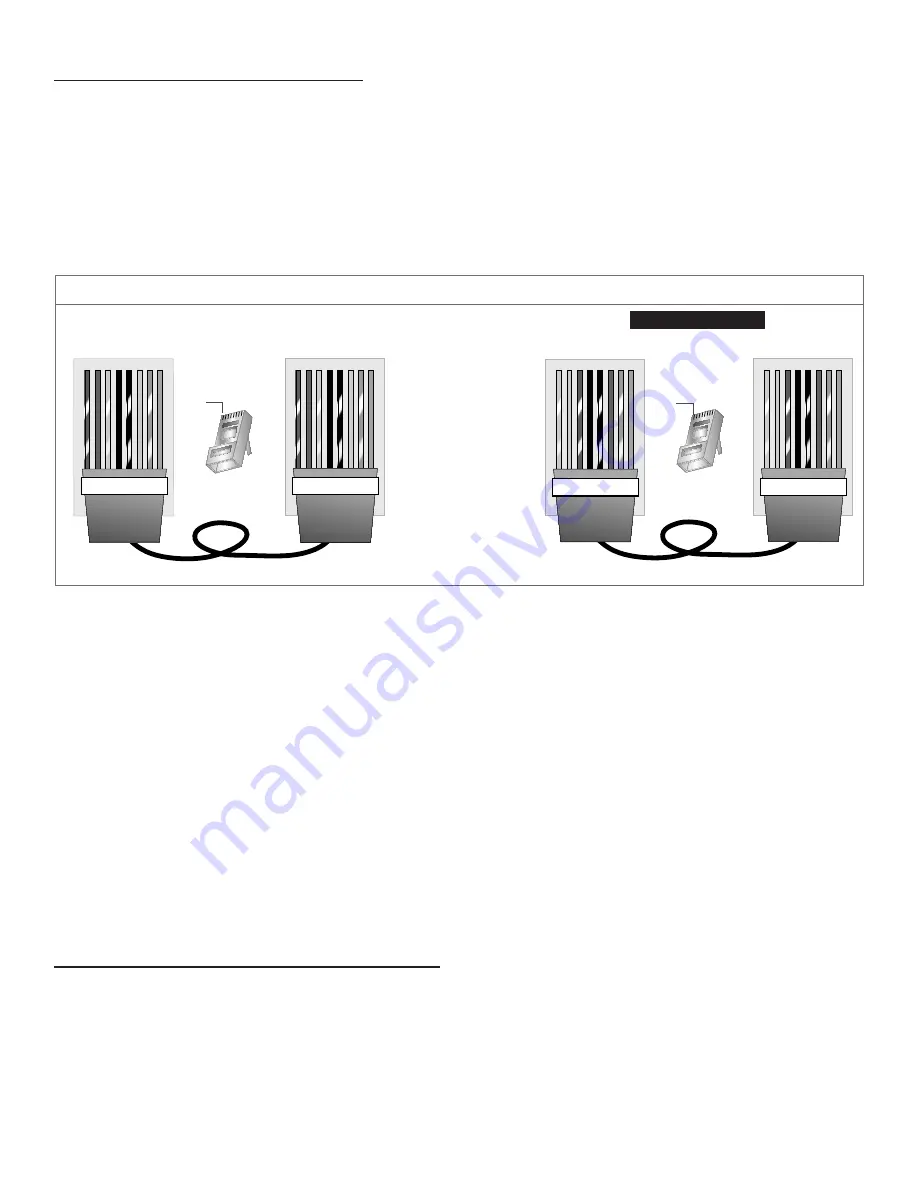
Please use a standard (T-568A or T-568B) RJ-45 connection with Cat5e cable (regular Cat5, shielded Cat5, or Cat6 are 

all acceptable) to connect the keypad to the controller or another keypad. Never use a cable with a “Crossover” con-

nection in which the two ends of the cable are wired differently.

When running your Cat5e cable, you have two options: 1) use cable of predetermined lengths that have the RJ-45 

plugs attached by the manufacturer, or 2) use a crimping tool to attach the RJ-45 plugs yourself after you have run the 

Cat5e cable. With option 1) you don’t have to worry about the connections being solid and correct, but you’ll likely have 

to cut larger holes through the framework of your house to get the cables into position. This option will cost a little more 

because you are likely to have excess cable since you can only buy in predetermined lengths. Option 2) allows you to 

buy your Cat5e cable in bulk and run exactly the length you need for each connection. But you’ll have to terminate each 

end with an RJ-45 plug yourself.

Addendum

Instructions:

Start on one end and strip the cable jacket off (about 1”) using a stripper or a knife. Be extra careful not to nick the 

wires, otherwise you will need to start over.

Spread, untwist the pairs, and arrange the wires in the order of the desired cable end. Flatten the end between your 

thumb and forefinger. Trim the ends of the wires so they are even with one another, leaving only 1/2” in wire length. 

If it is longer than 1/2” it will be out-of-spec and susceptible to crosstalk. Flatten and insure there are no spaces 

between wires.


Hold the RJ-45 plug with the clip facing down or away from you. Push the wires firmly into the plug. Inspect that 

each wire is flat and even at the front of the plug. Check the order of the wires. Double check again. Check that the 

jacket is fitted right against the stop of the plug. Carefully hold the wire and firmly crimp the RJ-45 with a special 

RJ-45 crimping tool.

Check the color orientation, check that the crimped connection is not about to come apart, and check to see if the 

wires are flat against the front of the plug. If even one of these are incorrect, you will have to start over.

We recommend use of our EZ-RJ45 Crimper Tool and our EZ-RJ45 Tips to make the this job MUCH easier.  With 

the EZ-RJ45 system, the eight little wires of the Cat5 or Cat6 cable can be pulled completely through the EZ-RJ45 

Tips, making color-coded wire verification easy.

Tips for Running Cat5e and Connecting to RJ-45:

•  If you are pulling cables through hole, it is easier to attach the RJ-45 plugs after the cable is pulled.

• Odd numbered pins are always striped, even numbered pins are always solid colored. 

• Looking at the RJ-45 with the clip facing away from you, Brown is always on the right, and pin 1 is on the left. 

• No more than 1/2” of the Ethernet cable should be untwisted, otherwise it will be susceptible to crosstalk.

• Do not deform, do not bend, do not stretch, do not staple, do not run parallel with power cables, and do not run Cat5e 

cables near noise inducing components.

RJ-45 Plug

Clip is pointed

away from you

T-568B

o


O


g   B   b


G   br  BR

1 2 3 4 5 6 7 8

T-568B

o


O


g   B   b


G   br  BR

1 2 3 4 5 6 7 8

RJ-45 Plug

Clip is pointed

away from you

T-568A

1 2 3 4 5 6 7 8

  g   G   o


B   b   O   br BR

T-568A

1 2 3 4 5 6 7 8

  g   G   o


B   b   O   br BR

O

o

G

g

B

b

BR

br

Orange

Orange striped

Green

Green striped

Blue

Blue striped

Brown

Brown striped

Wire Key

T-568A Straight-Through Cat5e Cable

T-568B Straight-Through Cat5e Cable

Pin 1

Pin 1

Recommended

T-568A/T-568B Standardized RJ45 to Cat5e Connection 

Figure 13

Summary of Contents for MC-66 Multi-Zone

Page 1: ...dio Control Owner s Manual MC 66 Multi Zone Controller MCA 66 Multi Zone Controller Amplifier Home Theater Direct Toll free 866 HTD AUDIO 483 2834 www htd com info htd com Copyright Home Theater Direct Inc V 07 06 17 ...

Page 2: ...ower Cord Protection Route the power cord so that it is not likely to be walked on or pinched by items placed upon or against them paying particular attention to the plugs receptacles and the point where the cord exits from the appliance Cleaning Unplug the appliance from the wall outlet before cleaning Do not use liquid cleaners or aerosol cleaners Use a cloth lightly damp ened with water for cle...

Page 3: ...areil 11 Utilisez uniquement des fixations accessoires spécifiés par le fabricant 12 Utilisez seulement avec un chariot un support un trépied une console ou table spécifié par le fabricant ou vendu avec l appareil Lorsque vous utilisez un chariot soyez prudent lorsque vous déplacez l ensemble chariot appareil pour éviter les blessures en cas de chute 13 Débranchez cet appareil durant les orages ou...

Page 4: ...3 This Page is Intentionally Blank ...

Page 5: ... you have any questions please call us toll free at 1 866 483 2834 during business hours M F 8am 6pm CST We re here to help and to make sure you are getting the most out of your new whole house audio system IMPORTANT WARNINGS AND HELPFUL TIPS Please note that while we refer to Cat5e throughout this manual Cat5 and Cat6 can also be used with equal effectiveness 1 Never connect or disconnect Cat5e c...

Page 6: ...er Multiroom Controller MC 66 Zone Status 1 2 3 4 5 6 Power button and blue indicator light Zone status lights blue indicate when a zone is active IR Repeater Outputs Con nect to single or dual IR emit ters to pass IR signal to other audio components Stereo pre amp outputs for each zone fixed and variable connect to separate 12 channel amplifier RJ45 connectors for connecting Cat5e cable to keypad...

Page 7: ... all keypads Power Button Multi function but ton used to power on power off and mute the keypad Can also be used to power off all keypads Volume indicator lights Select from up to six centrally located sources LCD Screen displays selected source volume level and setup menu options Two RJ45 con nectors Use one for connect ing Cat5 cable or Cat5e or Cat6 to control ler Optionally use the other RJ45 ...

Page 8: ...ther connector is used for connecting up to two total keypads in each zone This is discussed in more detail later in this section Once connected keypads will control the zone in which the Cat5e cable is inserted on the controller Daisy Chaining Keypads It is possible to connect a maximum of two keypads into any one zone by daisy chaining the keypads together using the extra RJ 45 connector on the ...

Page 9: ... drywall 3 Install KC6 KC7 4 Install KC6 KC7 plate 5 Check distance between KC6 KC7 plate and Drywall Vol Vol Power Mute Source Vol Vol Power Mute Source Vol Vol Power Mute Source Vol Vol Power Mute Source 2 Apply tape directly to drywall 4 Install KC6 KC7 plate Vol Vol Power Mute Source 3 Install KC6 KC7 5 Check distance between KC6 KC7 plate and Drywall Vol Vol Power Mute Source Vol Vol Power Mu...

Page 10: ... multi channel amplifier using stereo RCA type patch cables as shown in Figure 4 In most cases you should set the Fixed Variable switch to Variable This allows the keypad to control the volume level in that zone Select ing the Fixed switch position is recommended when you set up multiple sub zones see Sub zones pg 9 in one zone where each of the pairs of speakers in that zone are independently con...

Page 11: ...C 1 IR OUT IR IN SOURCE INPUT RS232 INTERFACE KEYPAD PORTS 1 2 3 4 5 6 L R 4 3 2 1 5 6 12V DC TRIGGER OUT IN VARIABLE FIXED ZONE 1 L R L R L R L R L R L R ZONE 2 ZONE 3 ZONE 4 ZONE 5 ZONE 6 VARIABLE FIXED Power Multiroom Controller MC 66 Zone Status 1 2 3 4 5 6 FUSE T1A 250V AC 120V 60Hz Power Consumption 70W IR OUT IR IN SOURCE INPUT RS232 INTERFACE KEYPAD PORTS 1 2 3 4 5 6 L R 4 3 2 1 5 6 12V DC...

Page 12: ...gger output will be inactive and the DMA 1240 1275 will automatically return to sleep mode Please note that the Power Button on the front of the DMA 1240 1275 should be pressed in with the blue power indicator light illuminated Trigger mode using the included Trigger cable is preferred We generally don t recommend use of the Auto setting for this application Auto mode detects the presence of an au...

Page 13: ...hin the emitter is located on the bottom portion of the emitter This is why the emitters should be attached on top of the device s receiving eye that you wish to control FUSE T1A 250V AC 120V 60Hz Power Consumption 70W IR OUT IR IN SOURCE INPUT RS232 INTERFACE KEYPAD PORTS 1 2 3 4 5 6 L R 4 3 2 1 5 6 12V DC TRIGGER OUT IN L R PRE OUT ZONE1 FIXED VARIABLE L R PRE OUT ZONE2 FIXED VARIABLE L R PRE OU...

Page 14: ...and balance settings will be the same as you programmed them Repeat for all zones Using the KC6 Keypad Source Selection Buttons Select a source by pressing on one of the 6 source buttons Volume Control Press the volume up or volume down button to control the volume You can press these buttons once for a incremental increase or decrease or press and hold the buttons for continuous increase or decre...

Page 15: ...ating to appropriate feature the KC7 screen will display the feature balance treble or bass that you have current control over along with a graphic below showing the current setting See Balance Example Screen Figure 10 Use the volume buttons to make adjustments to current settings and use the source buttons on the face of the keypad to navigate to the next or previous feature Adjusting Font Color ...

Page 16: ...t is in sleep mode by pressing any button Press and hold the power button for approximately 1 second to power off the keypad If keypad is in sleep mode it must first be awakened to then power off If volume is muted the keypad can be powered off as normal with out being un muted Power ALL OFF It is possible to turn off every keypad connected to the controller by simply pressing the power button on ...

Page 17: ...mplifier or volume control Steps for Splicing Wires 1 Strip back about of insulation on the ends of the two wires to be spliced together 2 Strip back about of insulation on the end of a 6 10 single length of the same wire 3 Twist the three bare wire ends together tightly 4 Solder the twisted connection using electrical solder 5 After the solder cools wrap plastic electrical tape tightly around the...

Page 18: ...s firmly into the plug Inspect that each wire is flat and even at the front of the plug Check the order of the wires Double check again Check that the jacket is fitted right against the stop of the plug Carefully hold the wire and firmly crimp the RJ 45 with a special RJ 45 crimping tool Check the color orientation check that the crimped connection is not about to come apart and check to see if th...

Page 19: ...haring Sources Across Multiple Controllers Figure 14 CD Player 1 Tuner CD Player 2 Power Multiroom Controller MC 66 Zone Status 1 2 3 4 5 6 FUSE T1A 250V AC 120V 60Hz Power Consumption 70W IR OUT IR IN SOURCE INPUT RS232 INTERFACE KEYPAD PORTS 1 2 3 4 5 6 L R 4 3 2 1 5 6 12V DC TRIGGER OUT IN ZONE 1 L R L R L R L R L R L R ZONE 2 ZONE 3 ZONE 4 ZONE 5 ZONE 6 VARIABLE VARIABLE FIXED FIXED Power Mult...

Page 20: ...n mode The amplifier in a zone will shut down until the problem has been resolved This is usually an indication of a short in the speaker cable or speaker connection If you have any questions please contact HTD at info htd com or toll free 1 866 HTD AUDIO 483 2834 Specifications Stereo Zones Stereo Inputs Pre amp outputs switchable between Fixed and Variable for each zone RS232 connection for Vale...

Reviews: