THT32
EN - 8
5 OPERATING
INSTRUCTIONS
5.1 DESCRIPTION OF THE MAIN INTERFACE
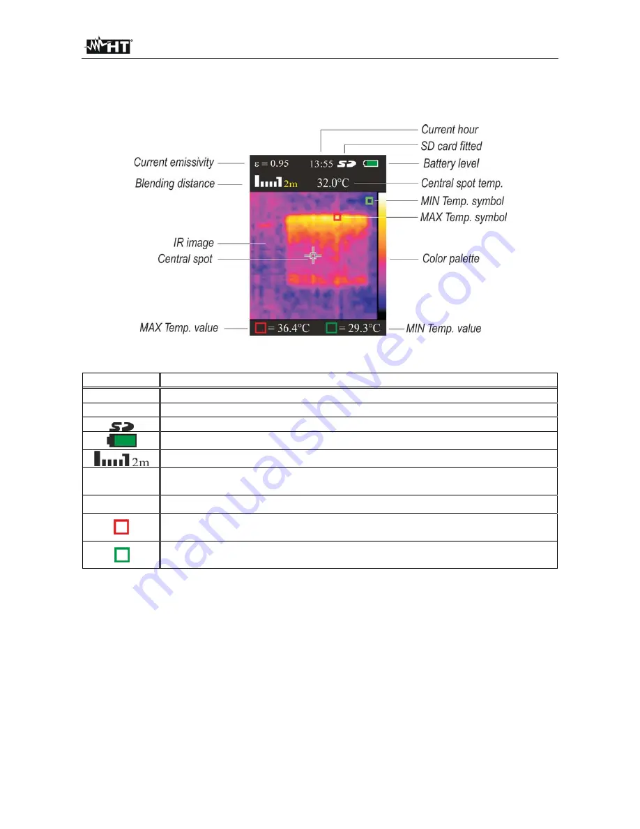
The instrument shows the following main interface on the display:
Fig. 4: Main instrument interface
The meaning of the symbols found on the display is described below.
Symbol Description
=0.95
Set value of object emissivity (see § 5.2.1)
13:55
Indication of the system's current time
Indication of fitted micro SD card
Indication of battery charge level
Indication of distance in
“
Blending Fusion
”
function (see § 5.1.1)
32.0°C
Indication of the temperature value associated with the central steady
cursor
Palette
Indication of colour palette (see § 5.2.4)
Cursor (red) associated with the Maximum temperature of the image on
the display.
Cursor (green) associated with the Minimum temperature of the image on
the display.
5.1.1 Adjusting the distance of the object in Blending Fusion function
The instrument is provided with the
“
Blending Fusion
”
function, which allows aligning the
infrared and the visual image. This function is therefore especially useful in the instant
search of heat maps found on the surface of the framed object. Due to the different
position of the lens and of the built-in photo camera, when the object is close to the lens,
the visual image tends to become bigger, while the IR image tends to reduce. When the
object is more than 2m far from the lens, this effect tends to disappear. The instrument
allows setting the distance of the object in order to compensate the effect at distances
shorter than 2m. Proceed as follows:
1. Frame the object to be measured
2. Use the arrow keys
or
to adjust the infrared/visual image mixing percentage from
0%
to
100%
in steps of
25%
.
3. Use the arrow keys
or
to set the value of distance between lens and object. The
following values are available:
0.5m (1.6ft), 1m (3.3ft), 2m(6.6ft)
and
3m(9.8ft)


