


HRW HPE-BNMBUS V401 Manual 180307 E. & O. E. / Subject to change without notice
Page 11 of 24
Gateway Point Structure
With the exception of the DVIF, the point configurations are made up of point (AV) number, four bytes of
configuration plus the end codes.
Meter addressing AV’s are up to four bytes, data point AV’s are up to three bytes. The separate
configuration elements of the DVIF or AV’s are separated by commas (,).
If byte locations are fixed as 0, that will be signified in the following descriptions by red character
0
. As
we explain the structure we will include previously explained settings and indicate those with no direct
relevance in the explanation with
blue
characters.
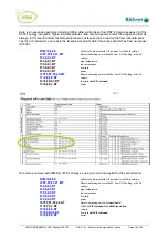
Common DVIF
The DVIF setting configures the common meter data point address which will be attached to all meter
address points (M end code).
The configuration starts with ‘DVIF=’ followed by up to three bytes of DIF/VIF addressing information
and one spare byte.
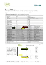
Using the time/date data point from the RSP1 table on page 9.
DVIF=4,6D,0,
0
Because there are no other data points above the time/date in the read out sequence starting with DIF
04 then this configuration can be simplified:
DVIF=4,0,0,
0
If however the time/date is not required but energy with 1kWh resolution is applicable for all meters, so
suitable as a common data point for all AV’s used for meter addressing, then:
DVIF=4,6,0,
0
The inclusion of the VIF 06 in the above configuration will ensure the gateway skips over the earlier
data point with DIF 04, the time/date data point which has VIF 6D, and reads the energy data point
which is the second point in the RSP read out sequence which has DIF 04.
Meter Address (M)
Primary Addressing
The M-Bus device addressing point may be configured for identifying a device based on the M-Bus
Primary address (from 0…255) as set by the user of the Secondary address which is typically the
device serial number.
Primary address configuration uses the first configuration byte to signify Primary address is being used
by entering
P
in this byte. The fourth configuration byte is used to indicate the Primary address which
may be a number from 0…255. Using Register 4 as example, with Primary address 12:
4=P,
0
,
0
,12,MT
The end code M configures the Register as a Meter addressing point so the resultant Register value
read in will be according to the DVIF’s data point address. The end code T means the point will be read
according to the read cycle period TS.