


HIROSE ELECTRIC CO.,LTD.
ETAD-H0760
4
14 / 17
FORM HC0011-9-2
5. Notes
*Packing and storage
To pack or store assemblies, make sure overlapped connectors will not apply extreme load to
the lack section.
If load is applied to the lock section under high temperature and humidity for a long period of
time, the lock section will be deformed which could lead poor fitting.
*Excessive external force applied to connectors could cause failure or damage. Therefore,
avoid forced insertion or removal, dropping impact, cable wiring (pull, twist) and such.
Note) Breaking strength of lock is approx. 30 N when connector is pulled in straight
direction. Please avoid excessive force is applied to the connector.
Note) Retention force is approx. 7 N / Pin. Please avoid excessive force is applied to
particular cable.
*When wiring the cable inside the device, make sure that the cable is routed with a margin
so that it will not be in a stretched state or in a state where excessive tension is applied.
*Check with the cable manufacturer for cable flexibility.
*If the rubber seal is damaged, the connector is deteriorated water resistant performance.
Therefore, do not use the connector whose rubber seal is damaged.
*
When using the DF62WP series, use the screws shown in the drawing for the
fixing screws.
●
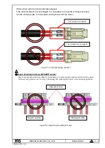
Cable bending
When bending the cable, provide a straight part from the end face of the connector as
shown in the figure below and bend it.
(It depends on the flexibility of the cable, but please bend it at the position of 30 mm as a
guide.)
Do not bend sharply from the end face of the connector or stretch the base of the cable
because it will put a load on the terminal contact part and the terminal crimping part
and cause contact failure and waterproof failure.
Sudden bending, tense bending
Straight
Figure 5-1. Cable bending
4
4
4
4
Min:30mm
Min:30mm
Bending with a straight
part
Min:30mm
Min:30mm


