background image


HIROSE ELECTRIC CO.,LTD.


ETAD-H0760


4


4 / 17


FORM HC0011-9-2 


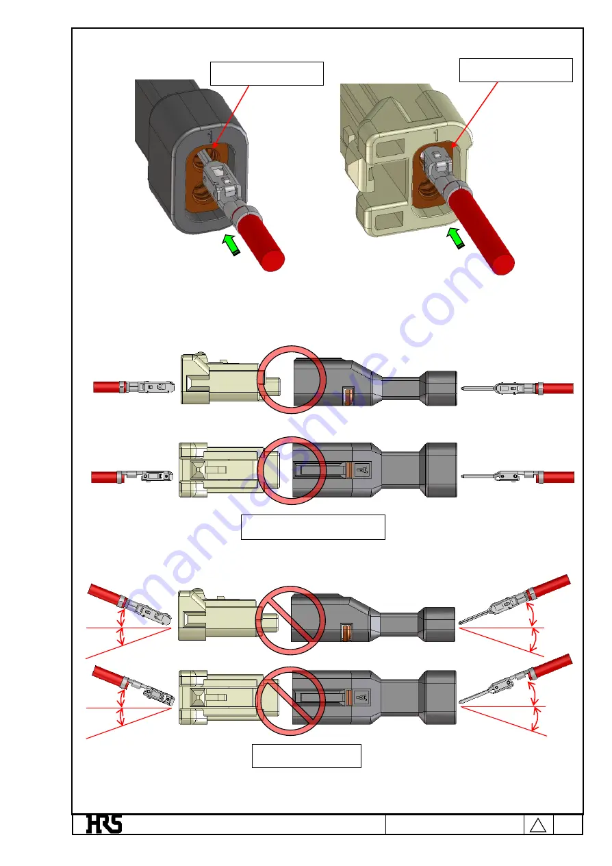
Insert the crimped terminal to pass through the hole of wire seal. 


To maintain performance reliability,insert the crimp terminal straight. 


Horizontal insertion 


Tilted insertion 


Hole of wire seal 

Hole of wire seal 

Figure 3-2. Terminal insertion 

Figure 3-3. Prohibition of diagonal insertion 

Summary of Contents for DF62W Series

Page 1: ...ct pitch 2 2 mm Shape of connection terminal C Crimping case Name DF62WP No of poles 2 to 9 Indicates that the connector is a composite connector with a number of poles separated by it Connector types EP In line plug Contact pitch 2 2 mm Shape of connection terminal C Crimping case Application WP Waterproof pin COUNT DESCRIPTION OF REVISIONS DESIGNED CHECKED DATE 4 12 DIS H 00006326 KI SUGAWARA ST...

Page 2: ...s DF62W EP 2226 PCF A Application EP In line Compatible cables 2022 AWG20 to 22 2226 AWG22 to 26 2830 AWG28 to 30 Shape packing SCF Socket terminal reeled SC Socket terminal separate PCF Plug terminal reeled PC Plug terminal separate Plating A Gold plating Blank Tin plating ...

Page 3: ...22 2226 2830 3 3 Insertion to crimping terminal sockets Insertion to DF62W EP 2 2C and DF62W S 2 2C Hold the cable of a crimped terminal and insert it to each terminal hole of crimping sockets Insert the terminal in the direction of arrows below The figures show insertion to DF62W 2poles connector For insertion place the crimped terminal and crimping socket lock in the following direction Before i...

Page 4: ...imped terminal to pass through the hole of wire seal To maintain performance reliability insert the crimp terminal straight Horizontal insertion Tilted insertion Hole of wire seal Hole of wire seal Figure 3 2 Terminal insertion Figure 3 3 Prohibition of diagonal insertion ...

Page 5: ...nt coming off Insertion to DF62WP series The figures show insertion to DF62WP 3 4 6 2EP 2 2C Hold the cable of a crimped terminal and insert it to each terminal hole of crimping sockets Insert the terminal in the direction of arrows below Crimped terminal lance holder Socket lance In line plug lance Target 5 85 mm Target 5 55 mm Plug terminal In line plug Direction of insertion Before inserting te...

Page 6: ...crimp terminal straight Do not mistake the terminal hole Insert the terminal in the direction of arrows below terminal hole 2poles Lock Right side Lance holder Upper Horizontal insertion Tilted insertion terminal hole 6poles terminal hole 4poles terminal hole 3poles Figure 3 6 Terminal orientation DF62WP Figure 3 7 Prohibition of diagonal insertion DF62WP Figure 3 8 Terminal hole position DF62WP ...

Page 7: ...ire seal to prevent coming off 3 4 Insertion of waterproof pin Compatible series DF62W EP 2 2C DF62W S 2 2C If you use waterproof pins insert them to each holes with designated terminal numbers Insertion direction is shown by arrows in the figure below Before inserting waterproof pin After inserting waterproof pin Waterproof pin Direction of insertion Target 1 7 mm Crimped terminal lance holder In...

Page 8: ...t the waterproof pin straight No orientation Direction of insertion Direction of insertion This surface is waterproof surface so take care not to damage the surface Horizontal insertion Tilted insertion Figure 3 11 Orientation of waterproof pins Figure 3 12 Prohibition of diagonal insertion of waterproof pin ...

Page 9: ...d terminal To remove crimped terminals that have been inserted pull the cable using the dedicated Removing jig DF62W RE MD while pushing up the crimping socket lance Using crimping socket after repair could induce decrease of lance strength and or wire seal damage Use new socket to avoid such failures Target 1 55 mm Target 1 85 mm To tap the waterproof pin to socket Removing jig DF62W RE MD Socket...

Page 10: ...ance with the hand lens Additionally insert the removing jig to push up the socket lance Keep the lance position and pull the cable Direction of insertion Direction of insertion Direction of insertion Direction of insertion Push up the lance Push up the lance Figure 3 15 Repair of crimp terminals Figure 3 16 Repair of crimp terminals ...

Page 11: ...anel side as a guide Insert the connector as far as it will go while maintaining the aligned position The shape of the panel is an example If the panel has a shape to prevent reverse mounting align the orientation with the protrusion shape before inserting Screw hole Direction of insertion Reverse mounting prevention shape Figure 4 1 Insertion into the panel Figure 4 2 Reverse mounting prevention ...

Page 12: ... into the panel and attach it 4 1 b Fixed with screws Install the screws with the connector fully inserted At this time do not fix the screws when the connector is biased in either the vertical or horizontal direction or when an excessive load is applied Horizontal insertion Tilted insertion Figure 4 3 Prohibition of diagonal insertion Figure 4 4 Screw fixing ...

Page 13: ...ews Remove screws 4 2 b Removing the connector Remove the connector from the panel At this time push the connector mating surface side to remove it Do not pull the cable to remove it as it may cause the terminal to come off Fitting surface Figure 4 5 Removing Screw Figure 4 6 Removing from the panel ...

Page 14: ...ure that the cable is routed with a margin so that it will not be in a stretched state or in a state where excessive tension is applied Check with the cable manufacturer for cable flexibility If the rubber seal is damaged the connector is deteriorated water resistant performance Therefore do not use the connector whose rubber seal is damaged When using the DF62WP series use the screws shown in the...

Page 15: ...HIROSE ELECTRIC CO LTD ETAD H0760 4 15 17 FORM HC0011 9 2 Sudden bending tense bending Bending with a straight part Figure 5 2 Cable bending DF62WP Straight Min 30mm Min 30mm Min 30mm Min 30mm ...

Page 16: ...he figure below and tie it at least 30 mm away from the end face of the connector Do not bind near the end face of the connector because it will put a load on the terminal contact part and the terminal crimping part and cause contact failure and waterproof failure Bundling near the end face Bunding with a straight part Figure 5 3 Cable bundling 4 Straight Min 30mm Min 30mm ...

Page 17: ...cause loosing the contact by stress Repair of waterproof seal DF62WP series The waterproof seal may shift by inserting or removing the connector from the panel In that case please use it after returning the waterproof seal to the normal position waterproof seal Misaligned state Regular position The terminals are aligned The terminals are not aligned Figure 5 4 Terminal binding direction Figure 5 5...

Reviews: