


VDPLAT1
HQ POWER
6
e.
Setup Checking
•
Check that connection from the LED CLUSTERS to the DRIVERS is correct.
•
Check that the power supply units are correctly connected and that the power load has not been exceeded (220V
- up to 16 panels in series / 120V – up to 8 panels in series).
•
Confirm that that power supply units stated voltage is the same as your local area.
•
Check that all connecting wires with the PC are correct and secure.
•
Connect the power and confirm that the LED on each driver is red. If the LED is not red, please check the driver
and replace with a new one.
•
Start the i.TOP software, if the LED matrix is not detected, the software will hint to the user that the LED matrix is
not found. Please check all connecting cables and hardware.
•
Select “Grid Test” from the control panel. Select “Color Change 3 color”. If the LED MATRIX screen changes from
one colour to the other with a grid of diagonals then all connecting cables are connected correctly.
3. System Card Setting
a.
Transmitter Card
The transmitter card is installed in the PC and acts as an interface between the PC hardware & software and the
LED matrix screen hardware.
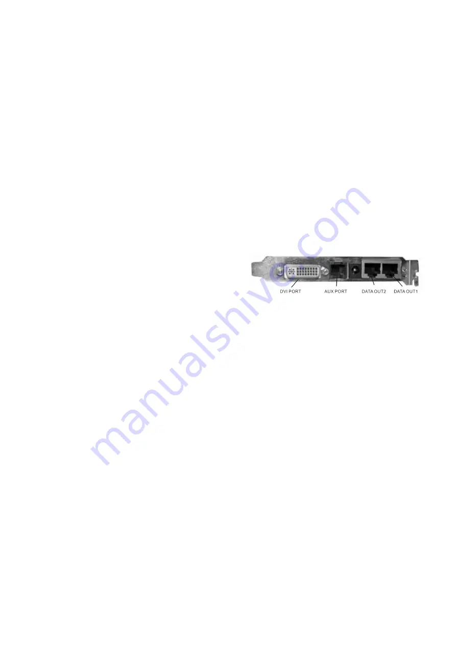
The PIN definitions of the DVI port must correspond to the PIN
definitions of the display card. The DVI cable provided must
be used to connect the DVI port to the display card.
•
OUT 1 & OUT 2 PORTS
OUT 1 & OUT 2 are 8P double-net card ports. OUT 1 is connected to the receiver using the net cable. Each port is
capable of transmitting 256 rows of information. At OUT 1 the data value ranges from row 1 to row 256. At OUT 2 the
data value ranges from row 257 to row 512.
•
AUX PORT
This port is a standard 6P telephone connection port. Connect the provided cable with the RS232 port. This port
allows control of the r variable, gray scale, LED matrix active area, LED matrix lock & LED matrix range.
•
POWER SUPPLY
Power Supply port is a 5V power supply connection for when the transmitter card is operating external of the PC.
b.
System Card Installation
Insert the transmitter card in the relevant available PCI slot in the PC.
•
Connect the transmitter card and the display card together using the DVI cable provided.
•
Connect the serial port (OUT 1) to the receiver card using the net cable.
•
Connect the transmitter aux port and the PC COM port using the cable provided.
•
Check that all connections are secure.
•
Calculate the correct positions for the receiver switches.
•
Turn on the computer and test the system
NOTE:
If the PC automatically reboots or turns off, please remove the DVI cable from the transmitter and try again. After the
Windows desktop has loaded reconnect the DVI cable.


