3
•
A pair of mounting screws (3.5 × 25) for sides (for EU) and a pair of mounting
screws (3.5 × 12) for top and bottom (for US).
•
Two secure screws: one Phillips head screw and one security-head Torx-10
screw.
•
Documentation.
Ports
•
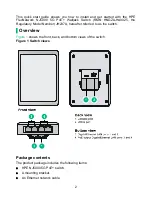
Four Gigabit Ethernet LAN ports
(bottom of unit)—Auto-sensing 1000BASE-T
Ethernet ports with RJ-45 connectors. Two ports can provide IEEE 802.3af or
802.3at power over Ethernet (PoE) to supply power to PoE Powered Devices
(PDs).
•
One Gigabit Ethernet uplink port
(back of unit)—Auto-sensing 1000BASE-T
Ethernet port with an RJ-45 connector.
•
One console port
(back of unit).
Reset button
The reset button is accessible through a hole on the side panel of the switch.
To reboot the switch:
1.
Insert a pin or paper clip into the reset button hole.
2.
Press and hold the button for 1 to 5 seconds.
3.
Release the button.
To change the operation mode for the switch:
1.
Insert a pin or paper clip into the reset button hole.
2.
Press and hold the button for 7 to 12 seconds until the management mode LED
flashes (10 times per second).
3.
Release the button. The management mode LED enters the target mode. If the
LED is on, the switch operates in managed mode. If the LED is off, the switch
operates in unmanaged mode.
To reset the switch to factory defaults:
1.
Insert a pin or paper clip into the reset button hole.
2.
Press and hold the button for more than 15 seconds until the status LEDs (Power
and Uplink) flash.
3.
Release the button.
LEDs
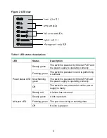
Figure 2
shows the status LEDs on the switch.


