


2
SY-P1001 / SY-P1002
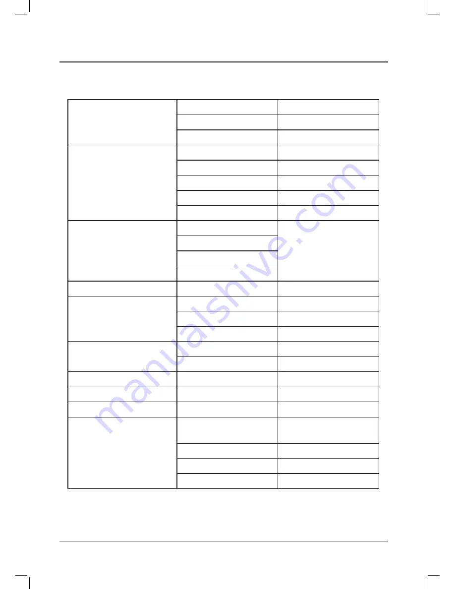
Specifications
Specifications
Rated Output Voltage
Balanced Master Output
0dBm
Unbalanced Sub Output
0dBm
Unbalanced Rec output
-10dBm
Input sensitivity for rated
output at maximum gain
Balanced Microphone channels -60dBm
Balanced Line 1-6 channels
-30dBm
Unbalanced Line 7-10 channels
-30dBm
Unbalanced Priority
0dBm
Insert
0dBm
Total Harmonic Distortion(T.H.D)
at 1KHz Rated output
Mic in to Master Output
Less than 0.2%
Line in to Master Output
Mic in to Sub Output
Mic in to Rec Output
Frequency Response
Rated Output 20Hz~20KHz
±3dB
Input Channel EQ
HIGH (12.5KHz)
±12dB
MID(2.5KHz)
±12dB
LOW(80Hz)
±12dB
Output Channel EQ
HIGH (12.5KHz)
±12dB
LOW(80Hz)
±12dB
Residual Noise
less than -90dB
Crosstalk
At 1KHz
less than -70dB
Phantom Power (balanced)
+18V DC
General
Power Source
AC 100~120V / 50~60Hz
AC 220~240V / 50~60Hz
DC 240 V
power Consumption
16Watts
Weight
5.3 kg
Dimensions
482(W)x325(D)x88(H)
* Specifications and design subject to change without notice for improvements.
Summary of Contents for SY-P1001
Page 1: ...Owner s Manual SY P1001 SY P1002...
Page 2: ...WARNING...
Page 13: ...11 SY P1001 SY P1002 Block diagrams...
Page 15: ...13 SY P1001 SY P1002...
Page 16: ......