HPA SY-P1001 Owner'S Manual Download Page 11

SY-P1001 / SY-P1002

Connections

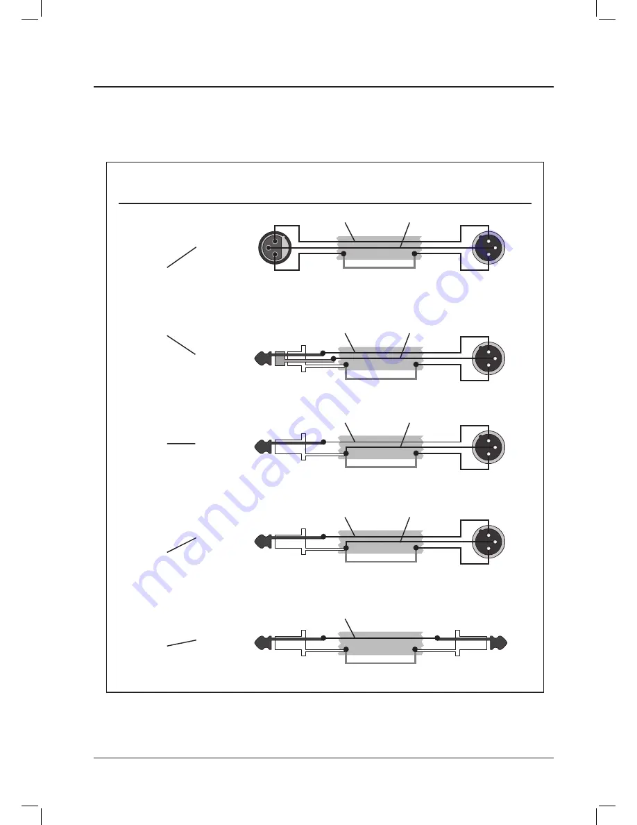
CONNECTOR AND CABLE CONFIGURATIONS

Connections

2

3

1

T

R

S

2

3

1

2

3

1

(XLR)

(XLR)

White(Red)/HIGH

A. XLR**

B. TRS PHONE

Black/LOW

Shield/GND

White(Red)/HIGH

Black/LOW

Shield/GND

T

S

T

T

S

S

2

3

1

(XLR)

(Standard Phone)

D. STANDARD

     PHONE

E. SHIELD/GND

     PHONE

White(Red)/HIGH

Black/LOW

Shield/GND

White(Black)/HIGH

Shield/GND

T

S

2

3

1

(XLR)

C. STANDARD

     PHONE

White(Red)/HIGH

Black/LOW

Shield/GND

Floating or Balanced
low impedance: most 
professional equipment
line in and line out,
microphones.

Unbalanced
low impedance: some
professional equipment
and microphones.

Unbalanced
high impedance: most 
hi-fi equipment.

Unbalanced
high impedance: most 
hi-fi equipment.

REMOTE DEVICE                                                                                                        REMOTE SIDE OF CABLE

DESCRIPTION                                                                              CABLE                  (Connector Type)

Connector and cable configurations recommended for use with the SY-P Series.


These cables are based on the use of auxiliary equipment that is isolated from the AC power mains.

Summary of Contents for SY-P1001

Page 1: ...Owner s Manual SY P1001 SY P1002...

Page 2: ...WARNING...

Page 3: ...SY P1001 SY P1002 Introductions 2 Features 3 Front panel controls 4 Rear panel controls 6 Connections 8 Block diagram 11 Specifications 12 Table of Contents Table of Contents...

Page 4: ...y features and how to use them Please take a great care in unpacking your set and do not discard the carton and other packing materials They may be needed when moving your set and are required if it e...

Page 5: ...s with PFL AFL switches 2 Band EQ control on every output channels Signal and peak indicator on each input channels DC 18V phantom power for condenser microphone on the MIC channel 1 and 2 Useful duck...

Page 6: ...A recommend for users to adjust TRIM control when PEAK indicator is flickering to make best performance 4 INPUT CHANNEL FADER These faders allow level adjust for each input channel 5 INPUT CHANNEL EQ...

Page 7: ...u to monitor the main output signal of output channel through headphone output 14 HEADPHONE LEVEL CONTROL This control allows you adjust the signal level of headphone output 15 HEADPHONE JACK TERMINAL...

Page 8: ...iter noise filters HPA would like to recommend using proper insert cable as below Pig 6 Tip Output Send to external device Sleeve Ground Ring Input Return from external device 4 SUB OUTPUT Sub output...

Page 9: ...e range from 50ohm to 600ohm 10 PRIORITY SWITCHES These switches allow talk over for MIC channel 1 and 2 All other input signals except priority input channel are muted when this function is activated...

Page 10: ...e wired as described Tip is Positive Ring is Negative Sleeve is Shield Connections Insert Points Amp Line Input Headphones Unbalanced Input Output AUX Send Ring Ring Tip Tip Sleeve Sleeve Send Return...

Page 11: ...STANDARD PHONE White Red HIGH Black LOW Shield GND Floating or Balanced low impedance most professional equipment line in and line out microphones Unbalanced low impedance some professional equipment...

Page 12: ...10 SY P1001 SY P1002 Connestions Block diagrams POWER POWER AMPLIFIER SY A360 ON OFF MICROPHONE MICROPHONE CASSETTE DECK CD PLAYER TUNER SPEAKERS POWER AMPLIFIER EMERGENCY PANEL...

Page 13: ...11 SY P1001 SY P1002 Block diagrams...

Page 14: ...ated output Mic in to Master Output Less than 0 2 Line in to Master Output Mic in to Sub Output Mic in to Rec Output Frequency Response Rated Output 20Hz 20KHz 3dB Input Channel EQ HIGH 12 5KHz 12dB M...

Page 15: ...13 SY P1001 SY P1002...

Page 16: ......

Reviews: