background image

Chapter 3

3-5

Operating the Jukebox

Operating the Control Panel

Op
er

atin

g

 th
e

Juke
b

o

x

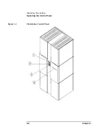
The numbers below refer to the numbers in Figure 3-1 on the previous page.

NOTE

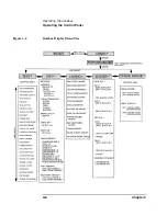
Figure 3-2 shows the jukebox menus available using the control panel selection 
buttons.

1

16-Character 
Display 

Displays status information and control panel 
information

2

Selection 
buttons

Pressed to perform the following operations:

LOAD

 used to load disks into the jukebox mailslot 

EJECT

 used to eject disks from the jukebox mailslot 

PREV

 scrolls the display choice backward by one 

NEXT

 scrolls the display choice forward by one 

CANCEL

 cancels the current operation or choice 

ENTER

 selects the displayed choice

3

Activity light

Lit differently to indicate the following:

 Steady Green - power is on

 Flashing Green - an optical drive is being accessed

 Amber - a fault occurred

4

Mailslot

Used to load and eject optical disks

Summary of Contents for SureStore 220mx

Page 1: ...HP SureStore 1200mx 2200mx Optical Jukebox User s Guide Edition 1 HP Part No C1104 90021 Printed in Greeley CO USA Copyright August 2000 ...

Page 2: ...d to the implied warranties of merchantability and fitness for a particular purpose Hewlett Packard shall not be liable for errors contained herein or for incidental or consequential damages in connection with the furnishing performance or use of this material Copyright August 2000 Printing History New editions of this manual incorporate all material updated since the previous edition The manual p...

Page 3: ...s call attention to a procedure or practice that could result in personal injury if not correctly performed Do not proceed until you fully understand an meet the required conditions CAUTION Cautions call attention to an operating procedure or practice that could damage the product if not correctly performed Do not proceed until understanding and meeting these required conditions NOTE Notes provide...

Page 4: ...apter 2 information about choosing and using optical disks Chapter 3 features description operating instructions and troubleshooting information Appendix A supplies and customer support Appendix B operating this jukebox on a SCSI bus Appendix C safety and regulatory information Glossary of Terms Index ...

Page 5: ...box as the Only Peripheral Two Host Adapters Basic SCSI Addressing 1 12 Removing the Customer Access Panel 1 12 Connecting a 10 Drive Jukebox One Host Adapter Bus 1 and 2 Daisy Chained LUN Addressing 1 14 Removing the Customer Access Panel 1 14 Connecting the Jukebox With Other SCSI Peripherals 1 16 Connecting Power 1 17 Configuring Write Verify 1 18 Installing the Wheel Chocks 1 19 Moving or Ship...

Page 6: ...ges 3 8 Top Level Menus 3 8 Second Level Menus 3 8 Loading a Disk into the Jukebox 3 10 Ejecting a Disk From the Jukebox 3 12 Entering the Administration Menu Password 3 13 Changing the Administration Menu Password 3 14 Setting the SCSI IDs 3 15 Setting the LUN Mode 3 15 Viewing the Current SCSI IDs 3 16 Changing the Current SCSI IDs 3 17 Setting an Operating Configuration 3 20 Retrieving Log Hist...

Page 7: ...3 Transfer Rates on the Bus B 4 Termination B 4 Single ended and Differential Interfaces B 5 Connectors B 5 The SCSI Bus and This Jukebox B 7 Adding Devices to the Bus B 8 Default SCSI IDs in the Jukebox When Using Basic SCSI Addressing and When Using LUN Mode B 11 C Safety and Regulatory Information Overview of this Appendix C 2 CDRH Regulations USA Only C 3 EC Radio Frequency Interference Statem...

Page 8: ...inigung C 7 English Translation of German Sound Emission Directive C 7 Turvallisuusyhteenveto C 8 Laserturvallisuus C 8 Huolto C 8 English Translation of Finland Regulatory Information C 9 Japanese VCCI Statement C 10 Glossary Index ...

Page 9: ...acement of Cartridge Labels 2 4 Figure 2 2 Write Protect Button Location 2 5 Figure 3 1 The Jukebox Control Panel 3 4 Figure 3 2 Jukebox Display Menu Tree 3 6 Figure 3 3 Loading a Disk 3 10 Figure B 1 Single ended and Differential Interfaces on This Jukebox B 7 Figure B 2 Four or Six Drives One Host Adapter Basic SCSI Addressing B 14 Figure B 3 10 Drives Two Host Adapters Basic SCSI Addressing B 1...

Page 10: ...x Figures ...

Page 11: ... 3 4 Troubleshooting 3 36 Table A 1 Basic Supplies and Accessories A 3 Table B 1 Default SCSI and LUN Setings in 4 and 6 Drive Jukeboxes B 11 Table B 2 Default SCSI and LUN Settings in the 10 Drive Jukebox B 12 Table B 3 LUN Mapping of a 10 Drive Jukebox if DRVs BUS 1 ID is Changed to an ID Different Than the Jukebox Controller IDs used are examples B 13 Table B 4 Possible Additional SCSI Addresse...

Page 12: ...xii Tables ...

Page 13: ...Chapter 1 Setting up the Disk Drive Setting Up the Jukebox 1 Setting Up the Jukebox ...

Page 14: ...ded and differential SCSI terminators one of each included in a 4 or 6 drive jukebox two of each included in a 10 drive jukebox this guide Items needed but not included with the jukebox SCSI cable with either a high density 50 pin Micro D or high density 68 pin Micro D connector depending on whether a single ended or differential interface is used single ended or differential SCSI host adapter wit...

Page 15: ...in a standard configuration Host computer CPU Operating system Optical jukebox application software Jukebox SCSI drivers may be included in optical jukebox application software above Jukebox High Availability Configuration The following list is a hierarchy of the system components needed to operate this jukebox in a high availability configuration Consult with your high availability vendor for ins...

Page 16: ...1 4 Chapter1 Setting Up the Jukebox Identifying Right Side Panel Features Identifying Right Side Panel Features Figure 1 1 Right Side Panel Features 10 Drive Jukebox Shown ...

Page 17: ...ace board The interface board has two types of interface single ended and differential Each type of interface has two ports 4 Power cord strain relief clip Used to route the power cord away from other connectors and provide strain relief for the power cord connection 5 Product serial number label Needed for service calls Write down your jukebox serial number before you call your service representa...

Page 18: ...ews secure the customer access panel to the side of jukebox during shipment from the factory These screws are removed during unpacking but should be replaced after installation is complete If the jukebox is ever reshipped these screws must be in place to properly secure the access panel ...

Page 19: ...s Clip type cables may be used if you first remove the mounted thumbscrew studs with a flat blade screwdriver If the thumbscrew studs are not removed interference between the cable and the studs may result Interface types available Single ended or differential SCSI selected by the interface selection switch on each interface card Number of interface cards available One card in 4 and 6 drive models...

Page 20: ...for the proper procedures See page Standard Configuration The only peripheral on a bus and the jukebox has 4 or 6 drives 1 9 and the jukebox has 10 drives and you are using two host adapters 1 12 and the jukebox has 10 drives and you are using one host adapter 1 14 The jukebox will share a bus with other devices 1 16 High Availability configuration Consult with your high availability vendor ...

Page 21: ...ct the jukebox NOTE The jukebox ships from the factory with two screws securing the bottom of the customer access panel to the side of the jukebox These screws are removed during the process of unpacking and removing the jukebox from the shipping pallet These screws may not have been replaced It is a good idea to use the screws to secure the access panel to the jukebox since they must be in place ...

Page 22: ...at the bottom of the right side C 5 Plug a SCSI terminator into the unused SCSI port of interface type you chose the example diagram shows the terminator at B1 because B2 was used for the cable If you are using the differential interface use a 68 pin high density terminator If you are using the single ended interface use a 50 pin high density active terminator Figure 1 2 Connecting a 4 or 6 Drive ...

Page 23: ...up the Disk Drive Setting Up the Jukebox If you are terminating a differential interface use a 68 pin high density terminator If you are terminating a single ended interface use a 50 pin high density active terminator 7 To continue with the installation go to Connecting Power in this Chapter ...

Page 24: ...placed It is a good idea to use the screws to secure the access panel to the jukebox since they must be in place if the jukebox is ever reshipped If you have to replace these screws they are 6 32 x 437 Refer to the following diagram in the next steps 2 Select single ended A or differential B interface using the SCSI interface selection switch see the arrow on the diagram The diagram shows connecti...

Page 25: ... type you chose the example diagram shows terminators for the two differential interfaces placed on the B1 port for each interface If you are using the differential interface use a 68 pin high density terminator If you are using the single ended interface use a 50 pin high density terminator 6 Plug a SCSI terminator into one of SCSI ports on each unused interface the example diagram shows the term...

Page 26: ...ews may not have been replaced It is a good idea to use the screws to secure the access panel to the jukebox since they must be in place if the jukebox is ever reshipped If you have to replace these screws they are 6 32 x 437 2 Remove the customer access panel by pulling on the bottom of the panel and then lifting it off see Figure 1 1 If screws are installed use a flatblade screwdriver or T 15 To...

Page 27: ...ifferential interface port uses a 68 pin high density terminator A single ended interface port uses a 50 pin high density terminator The same cabling can be done using the single ended ports CAUTION Do not daisy chain between single ended and differential interfaces 6 Plug a SCSI terminator into one of SCSI ports on each unused interface the example diagram shows the terminators on the single ende...

Page 28: ...ith one host adapter and with LUN addressing daisy chaining Bus 1 and Bus 2 together or a 10 drive jukebox using two host adapters LUN addressing and using both BUS 1 and Bus 2 interfaces a 10 drive jukebox with two host adapters and using LUN addressing There are many issues that must be considered when connecting other devices on a bus with this jukebox including the following how the jukebox is...

Page 29: ...rough the long cable slot at the bottom of the jukebox right side panel and out through the cable access hole at the lower left rear of the jukebox 7 on Figure 1 1 5 Plug the other end of the power cord into a three hole grounded outlet 6 Press the power switch ON 8 on Figure 1 1 When power is applied TESTING and NOT READY alternately display Once the poweron test completes approximately 1 5 minut...

Page 30: ... data will be written The second pass writes new data to that sector When write verify is configured to ON an additional pass is made over the sector This third pass verifies that all data is written correctly to the sector To add to the reliability of your data Hewlett Packard recommends that you maintain the default ON setting for write verify Note that when write verify is ON write operations t...

Page 31: ... to stabilize the jukebox in position Install the wheel chocks after the jukebox is moved to its operating position and all cables are in place Figure 1 5 Installing the Wheel Chocks 1 After all cables and panels are mounted roll the unit to its final position 2 Spread the chock apart slightly and slide it around the bottom of the wheel as shown on the left side of the figure above 3 Repeat Step 2...

Page 32: ...optical drive prior to moving the jukebox could result in damage to the optical drive mechanism CAUTION Turning off the jukebox in the next step could cause data loss if not done correctly Do not turn off power to the jukebox until you are sure the SCSI bus is inactive Removing power from a SCSI peripheral when the bus is active can result in data loss and or indeterminate bus states Check your ho...

Page 33: ...for unmounting and ejecting disks Ensure that there are no disks in the drives If you will be manually ejecting disks refer to Ejecting a Disk From the Jukebox in Chapter 3 CAUTION Failure to eject a disk from the optical drive prior to moving the jukebox could result in damage to the optical drive mechanism Failure to remove all disks from the storage slots in the jukebox could result in damage t...

Page 34: ...SCSI cable connections 6 Loosen the 1 2 inch nut securing each leveler foot and screw the four feet up to raise them away from the floor 7 Remove the chocks from the four caster wheels on the bottom of the jukebox WARNING Push the jukebox only from the right or left sides see Figure 1 1 Pushing the jukebox from either the front or back sides could result in the jukebox tipping over if a wheel catc...

Page 35: ...Using Optical Disks 2 Using Optical Disks ...

Page 36: ...sting to ensure it s magneto optical media is unsurpassed in quality far exceeding ISO ANSI and IEC industry standards requirements In addition HP conducts exhaustive media compatibility and interchange testing to ensure maximum interaction reliability between HP jukebox drives and HP media Using HP optical media with HP jukeboxes is the best way to ensure your data s integrity and accessibility T...

Page 37: ...ata cannot be altered or erased If you have a need for data security and audit trails write once disks may be a good disk choice Rewritable and write once disks come in sector sizes from 4 096 bytes sector down to 512 bytes sector see Table A 1 in Appendix A The sector size you choose depends upon what type of operating system you have in your host computer and which software package you use to ma...

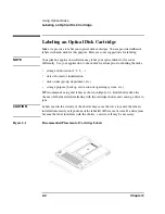
Page 38: ...torage slot location 1 2 3 date of format or initialization disk owner group department etc storage purpose backup old version of operating system etc HP recommends using end labels as shown in Figure 2 1 End labels reduce the chance of label material interfering with the cartridge shutter and causing a drive to jam CAUTION Labels used in the vicinity of the shutter may cause the drive to jam if t...

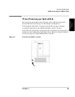
Page 39: ...cartridge see Figure 2 2 With rewritable optical disks write protecting the disk prevents overwriting existing files and prevents any additional file being written to the disk With write once optical disks existing files cannot be altered or erased regardless of whether or not the write protect button has been set However setting the button to write protect prevents writing additional files to the...

Page 40: ... of the cartridge near the shutter rather than on the end of the cartridge Store disks in a clean safe place when they are not in use Cleaning Disks Normally an optical disk does not require cleaning when used in a computer room or clean office environment If you are in an extremely dusty environment and are experiencing difficulties reading and or writing to a particular disk you may want to clea...

Page 41: ...Operating the Jukebox 3 Operating the Jukebox ...

Page 42: ...reting messages which appear in the display window loading optical disks into the jukebox ejecting optical disks from the jukebox entering the administration menu password changing the administration menu password setting SCSI IDs or logical unit numbers LUNs setting configurations retrieving performance information running tests for service use using online repair for service use only troubleshoo...

Page 43: ... SCSI IDs of the jukebox and its optical drives can be set and changed disks may be loaded and ejected configurations can be monitored and changed performance information can be viewed internal tests can be run and the jukebox can be secured from unauthorized use The figure and text on the next two pages show the user controls and mailslot The rest of the chapter describes all manual procedures av...

Page 44: ...3 4 Chapter3 Operating the Jukebox Operating the Control Panel Figure 3 1 The Jukebox Control Panel ...

Page 45: ...ction buttons Pressed to perform the following operations LOAD used to load disks into the jukebox mailslot EJECT used to eject disks from the jukebox mailslot PREV scrolls the display choice backward by one NEXT scrolls the display choice forward by one CANCEL cancels the current operation or choice ENTER selects the displayed choice 3 Activity light Lit differently to indicate the following Stea...

Page 46: ...3 6 Chapter3 Operating the Jukebox Operating the Control Panel Figure 3 2 Jukebox Display Menu Tree ...

Page 47: ... the next section for a list of messages Each time you push the NEXT or PREV button a task choice appears If you see an as part of the message it indicates there is a menu beneath that choice which you can access by pressing the ENTER key To display additional choices press the NEXT or PREV key Holding the NEXT or PREV or button down scrolls the display faster NOTE You can get back to READY at any...

Page 48: ...isplay other choices Second Level Menus You must enter a security code before accessing these functions See Entering the Administration Menu Password later in this chapter A default password of 000 000 000 is set at the factory You may want to change this default code to a private code to prevent unauthorized access to the jukebox See Changing the Administration Menu Password in this chapter TEST ...

Page 49: ...menu selection is flashing press ENTER to choose that selection or press PREV or NEXT to display other choices that available in that part of the menu In Figure 3 2 you can display the selections listed in boxes below the shaded choices by pressing ENTER when one of the shaded choices displays Press PREV or NEXT to scroll through the list To perform the displayed operation press ENTER ...

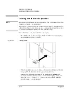
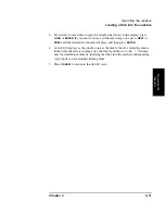
Page 50: ...on before proceeding with these steps Start with READY LOAD or EJECT in the display 1 Press LOAD on the jukebox control panel If none of these messages displays press CANCEL until READY displays Figure 3 3 Loading a Disk 2 When the mailslot opens insert a disk into the mailslot with Side A of the disk facing up The shutter end of the disk goes in the mailslot first When the disk is inserted it is ...

Page 51: ...ent storage slot press NEXT or PREV until the desired slot number displays and then press ENTER 4 LOADING displays as the jukebox moves the disk to the slot After the disk is loaded into the selected storage slot the display returns to LOAD You may now load additional disks by inserting the disks into the mailslot and repeating step 3 until you are finished loading disks 5 Press CANCEL to return t...

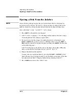
Page 52: ...x that contains an optical disk 3 If you want to select the storage slot number that shows in the display press EJECT or ENTER If you want to choose a different storage slot press NEXT or PREV until the desired slot number displays and then press ENTER See the note on the following page EJECTING displays as the jukebox moves the disk to the mailslot When the disk is in the mailslot the display ret...

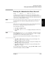
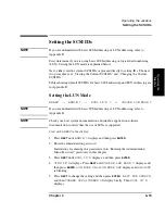
Page 53: ...he Administration Menu Password Start with READY in the display 1 Press NEXT until ADMIN displays 2 Press ENTER PSWD 000 000 000 displays and the first set of three zeros flashes NOTE If the default password 000 000 000 is still in effect accept this password by pressing ENTER three times once for each set of three zeros TEST displays which indicates you are in the menu tree below ADMIN If you hav...

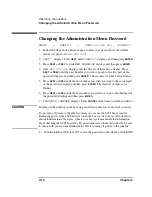
Page 54: ...wish to assign to the second part of the password displays and then press ENTER The third set of three zeros flashes 6 Press NEXT or PREV until the new number you wish to assign to the third part of the password displays and then press ENTER 7 PASSWORD CHANGED displays Press CANCEL three times to return to READY CAUTION Turning off the jukebox in the next step could cause data loss if not done cor...

Page 55: ...SE LUN MODE NOTE If you are unfamiliar with basic SCSI addressing or LUN addressing refer to Appendix B NOTE Check your host system documentation and jukebox application software documentation to verify that the use of LUNs is supported Start with READY in the display 1 Press NEXT until ADMIN displays and then press ENTER 2 Enter the administration password Instructions for entering this password ...

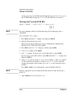
Page 56: ... are in Entering the Administration Menu Password previously in this chapter 3 Press NEXT until SCSI ID S displays and then press ENTER 4 VIEW ID S displays Press ENTER 5 BUS 1 displays If you want to view the IDs on Bus 1 press ENTER If you want to view the IDs on Bus 2 press NEXT until BUS 2 displays and then press ENTER 6 JKBX ID LUN or DRV ID LUN displays JKBX ID stands for the current ID of t...

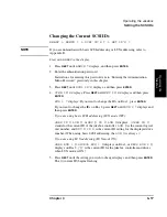
Page 57: ...nd then press ENTER BUS 1 displays If you want to change the IDs on Bus 1 press ENTER If you want to change the IDs on Bus 2 press NEXT until BUS 2 displays and then press ENTER If you are using basic SCSI addressing LUN mode OFF JKBX ID LUN or DRV ID LUN displays JKBX ID stands for the current ID of the jukebox controller LUN is the current logical unit number and DRV ID is the current ID setting...

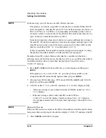
Page 58: ...is placed between the jukebox controller and the drives problems can result For this reason the jukebox will not accept IDs for the jukebox controller and drives that are more than one digit apart You will receive a CONFLICT message 6 Press NEXT or PREV until the new ID that you want displays and then press ENTER If the jukebox is set to LUN MODE ON go to Step 8 Only one ID can be changed and the ...

Page 59: ... sure the SCSI bus is inactive Removing power from a SCSI device when the bus is active can result in data loss and or indeterminate bus states Check your host system manuals for information about checking the SCSI bus status If your computer is connected to a LAN be sure to check with your system administrator before turning off power to the jukebox 10 Turn the jukebox OFF then ON to save the IDs...

Page 60: ...configuration is set and a confirmation message displays 5 If the current configuration setting is flashing press NEXT or PREV until the desired setting displays and then press ENTER OPTION SAVED displays and then the configuration s name and setting displays 6 Press CANCEL to return to READY CAUTION Turning off the jukebox in the next step could cause data loss if not done correctly Do not turn o...

Page 61: ...ould remain ON under normal conditions If the configuration is set to ON the jukebox runs with dual picker disk transport addressing ON if the configuration is set to OFF the jukebox runs with dual picker disk transport addressing OFF STARWARS ON OFF Used by service personnel only Should be set to ON during normal operation Toggles between ON and OFF The ON configuration enables the vertical senso...

Page 62: ... default setting of this configuration after a power cycling default setting is OFF REP RECOVERED ON OFF Toggles between ON and OFF When set to ON recovered errors are reported when set to OFF recovered errors are not reported CONF40 ON OFF Used by service personnel only Changing this configuration may result in a service call WRITE VERIFY ON OFF Toggles between ON and OFF When set to ON default w...

Page 63: ...R 4 Press NEXT until the name of the log you wish to access displays and then press ENTER A indicates that there are more selections beneath the displayed choice 5 After you are finished viewing log information press CANCEL to return to READY Information logs are described in the following table Table 3 2 Information Logs Log Name Description REVISION Jukebox firmware version number JUKEBOX Press ...

Page 64: ... for the drive numbered DRIVE FW Press ENTER to select the logs under this selection D REV x xx Drive firmware revision code D is the drive number and x xx is the code Press NEXT or PREV to select drive numbers DRIVE SN Press ENTER to select the logs under this selection D xxxxxxx Serial number of the drive where is the drive number Press NEXT or PREV to select drive numbers HARD ERROR Log of unre...

Page 65: ...lowing RECOVERY ERROR in this table RECOVERY ERROR Log of errors during the most recent move Returns either NO ENTRIES or the number of recovery errors Press ENTER to view the log for the currently displayed error or press NEXT to select the next error Log entries are described in the following rows HARDWARE ERR Internal diagnostics error number of the cause of the failure FRU 1 Field replaceable ...

Page 66: ...his information is valid for MOVE and EXCHANGE movements only DESTINATION 2 Element to which the second destination refers This information is valid for the EXCHANGE movement only ODOMETER Move number in which the error occurred MICROMOVE 1 First jukebox micro move for the original move command issued prior to the failure MICROMOVE 2 Second jukebox micro move for the original move command issued p...

Page 67: ... micro move for the original move command issued prior to the failure This is the last to be logged MICROMOVE ER Micro move error that occurred TOP or BOTTOM PICKER Displays either TOP or BOTTOM indicating which side of the disk transport mechanism was active at the time of the error NORTH or SOUTH THUMB Displays either NORTH or SOUTH indicating which thumb on the transport mechanism was active at...

Page 68: ...riptions of these tests are included in this manual only for your information Instructions for running internal tests are included in this guide to help you run tests if requested by service There is a possibility you may run one test as a result of troubleshooting this test is INIT ELEM STATUS Start with READY in the display 1 Press NEXT until ADMIN displays 2 Enter the administration password In...

Page 69: ...e instructions for running internal tests is included in this user guide and why the tests are described EXCHANGE DEMO Used by service personnel only Do not run this test if the jukebox contains disks with file system data on them This test moves randomly chosen optical disks to random storage slot locations This test displays FAIL if there are no disks in the jukebox or if all storage slots are f...

Page 70: ...disks in the jukebox or if all storage slots are full The drives and mailslot must be empty MAILSLOT IO Makes a combination of moves with a PASS FAIL result It moves an optical disk from the lowest numbered full slot to the mailslot with a random flip It then moves the cartridge back to its original slot with its original orientation This test displays FAIL if there are no disks in the jukebox or ...

Page 71: ...turns PASS FAIL No disks are required EMPTY DRIVES Used by service personnel only Do not run this test if the jukebox contains disks with file system data on them Moves disks out of the drive mechanism s and returns them to their home storage slot locations if the locations are known If the home storage location is not known the jukebox moves the disks into the first available empty storage slot E...

Page 72: ...D Allows the disk transport mechanics to run at full speed This setting should always be used in normal jukebox operation PLUNGE 1 2 SPD Used by service personnel only Allows the disk transport mechanics to run at half speed PLUNGE 1 4 SPD Used by service personnel only Allows the disk transport mechanics to run at quarter speed STARWARS The display shows 0 0 0 Each 0 indicates one of the paths th...

Page 73: ... forward position If NO THUMB is returned both thumbs are in the back position TOP THUMB Used by service personnel only Reports ON or OFF Looks at the top thumb sensor which reports whether or not the thumb that is currently on the top side of the disk transport mechanism is in the forward position If ON is reported the thumb is in the back position if OFF is reported the thumb is in the forward p...

Page 74: ...ce representative to replace a faulty drive while the jukebox remains online and active This feature is available only if enabled by your jukebox application software CAUTION Selecting online repair should be done only by an authorized service representative This procedure could cause the jukebox optical drives to become inactive ...

Page 75: ...service provider you can locate one by going to ww hp com Look under HP Services and Support NOTE If a service call is necessary gather the following information before calling your service provider model of your jukebox serial number brand and model of your host computer brand and model of your host computer SCSI adapter jukebox application software you are using and its version any jukebox drive...

Page 76: ... cables is reported Ensure that only one SCSI device type single ended OR differential exists on the SCSI bus Verify that the SCSI interface selection switch is set correctly either single ended or differential Verify that the terminator is the correct type single ended or differential If steps above are unsuccessful call your service representative Power to the jukebox failed while a disk was in ...

Page 77: ...s Press CANCEL Insert the disk in the mailslot again See Loading an Optical Disk into the Jukebox in this chapter for the correct disk loading orientation If the light bar on the front panel is orange cycle power to the jukebox Try to load the disk again when READY displays If the disk is in the mailslot correctly and these error messages repeat call your service representative Disk inserted in th...

Page 78: ...ur host and application documentation for recovery procedures If no procedures are available call your service representative Disk inserted in the mailslot but MAILSLOT SENSOR displays The jukebox mailslot sensors may have failed Remove and then re insert the disk If this does not correct the problem call your service representative Disk eject attempted but an EJECT ERROR message displays Press CA...

Page 79: ...procedures If no procedures are available call your service representative Disk eject attempted but SOURCE NOW EMPTY displays The application software moved the disk from the slot you chose before your eject command executed Press CANCEL You may have to wait for the application to replace the disk into the slot before attempting another eject Disk eject attempted but MAILSLOT FULL displays A disk ...

Page 80: ... write to the disk Check the host file system access permissions Eject the disk and check that the write protect tab on each side of the disk is in the write enabled position Check your application software If steps above are unsuccessful call your service representative Ensure that the SCSI bus is inactive before removing power to the jukebox Removing power to a device on an active SCSI bus can c...

Page 81: ...Supplies and Customer Support A Supplies and Customer Support ...

Page 82: ...Supplies and Customer Support Overview of This Appendix Overview of This Appendix This appendix provides information on the following topics supplies and accessories shipping screw specifications HP customer support ...

Page 83: ...ort Table A 1 Basic Supplies and Accessories Item HP Part Number 9 1 and 8 6 Gbyte Optical Disks Rewritable optical disk 4 096 bytes sector 9 1 Gbytes single disk C7983A Write once optical disk 4 096 bytes sector 9 1 Gbytes single disk C7984A Rewritable optical disk 2 048 bytes sector 8 6 Gbytes single disk C7985A Write once optical disk 2 048 bytes sector 8 6 Gbytes single disk C7986A Rewritable ...

Page 84: ... 2 3 Gbytes single disk 92279F Write once optical disk 512 bytes sector 2 3 Gbytes single disk 92289F SCSI Cables 50 Pin Low Density to 50 Pin High Density 1 0 m 3 3 ft clip latch to thumb screw K2296 1 5 m 4 9 ft clip latch to thumb screw K2297 0 9 m 2 9 ft thumb screw to thumb screw K2294 1 5 m 4 9 ft thumb screw to thumb screw K2295 50 Pin High Density to 50 PinHigh Density 0 5 m 1 6 ft thumb s...

Page 85: ...humb screw C2907A 20 0 m 65 6 ft thumb screw to thumb screw C2916A 68 Pin High Density to 68 Pin High Density 0 9 m 2 9 ft thumb screw to thumb screw C2911A 2 5m 8 2 ft thumb screw to thumb screw C2924A 10 0 m 32 8 ft thumb screw to thumb screw C2925A 20 0 m 65 6 ft thumb screw to thumb screw C2926A SCSI Terminators 50 pin active high density molded C2904A 68 pin differential high density molded C...

Page 86: ...ave a service contract with HP contact your nearest HP dealer or sales office Dealers and sales offices are found at www hp com under the HP Services and Support tab NOTE Before calling please record the following information and have it ready when you contact your service representative model number of your jukebox serial number brand and model of your host computer brand and model of your host c...

Page 87: ...unable within a reasonable time to repair or replace any product to a condition as warranted customer will be entitled to a refund of the purchase price upon prompt return of the product 4 HP products may contain remanufactured parts equivalent to new in performance or may have been subject to incidental use 5 The warranty period begins on the date of delivery or on the date of installation if ins...

Page 88: ...nt that all such damages are determined by a court of competent jurisdiction to have been directly caused by a defective HP product 9 TO THE EXTENT ALLOWED BY LOCAL LAW THE REMEDIES IN THIS WARRANTY STATEMENT ARE CUSTOMER S SOLE AND EXCLUSIVE REMEDIES EXCEPT AS INDICATED ABOVE IN NO EVENT WILL HP OR ITS SUPPLIERS BE LIABLE FOR LOSS OF DATA OR FOR DIRECT SPECIAL INCIDENTAL CONSEQUENTIAL INCLUDING L...

Page 89: ...Operation on a SCSI Bus B Operating This Jukebox on a SCSI Bus ...

Page 90: ...target usually a peripheral device fulfills the request Initiators and targets identify themselves on the bus by a SCSI ID The ID is designated by the user and is set electronically or manually depending on the device In addition to identifying a device on the bus the ID also determines the priority of the device during contention among the devices for use of the bus The narrow SCSI bus with its e...

Page 91: ...e device ID does not determine where the device is physically placed on the bus LUN Addressing SCSI IDs are the top level method of addressing devices on the bus Another method of addressing is also available logical unit numbering LUN This method enables a complex device such as a jukebox to group its internal SCSI devices to a single SCSI ID The complex device is identified by a SCSI ID but this...

Page 92: ...ion is Ultra also known as Fast 20 which is 20 MB s transfer rate on a narrow bus and 40 MB s on a wide bus Termination To keep signals on the SCSI bus from being reflected terminators must be placed at each end of the physical bus These terminators may be either active or passive Passive termination is a resistor network Active termination uses a voltage regulator the active component to regulate...

Page 93: ...uired the maximum length of the bus to be reduced to 3 meters 9 8 feet The differential bus uses two lines for each signal and measures the voltage difference between the two signals Differential retains more signal quality than single ended and is not as sensitive to noise allowing for a longer cable length The maximum allowable length of a differential bus is 25 meters 82 feet for all types buse...

Page 94: ...together 50 pin low density ribbon usually internal to the host Wide devices 68 pin use the following connectors 68 pin high density Micro D connector external This connector is similar to a D type connector but longer and slimmer and with smaller pin holes placed closer together This connector is becoming the most common 68 pin high density ribbon usually internal to the host ...

Page 95: ...he differential interface accepts a wide bus in its 68 pin connector but only uses the 50 data and control lines that comprise the narrow portion of the bus The other 18 lines that provide the upper IDs and data of the wide bus are ignored Note that all lines of the wide bus pass through the two 68 pin differential connectors The wide bus is maintained as a wide bus The single ended connectors are...

Page 96: ...es on the bus can be affected Consider the quantity of data that the bus will have to carry the frequency of data transfer and the priority of this data transfer in your business If you are using the jukebox as a backup or archive device the demands on the jukebox will be different than if the jukebox is used for near online storage where requests for data are more random in both frequency and amo...

Page 97: ... lower eight data lines transfer commands and messages allowing all devices regardless of size to co exist on the bus However data transfers and device addressing occur on the higher bits Since a narrow device can t see the upper 8 data bits that translates to it not being able to see wide devices with a SCSI ID above 8 Remember the host adapter is a device so if you re mixing wide and narrow devi...

Page 98: ...tors to reduce noise sensitivity Never terminate the bus at any place except the physical ends Terminating the bus in the middle will probably cause the bus to become inoperable or operate in a state that could cause data loss If devices are on both sides of the host computer adapter such as hard drives internal to the host computer and a jukebox external to the host computer make sure that there ...

Page 99: ...tion on a SCSI Bus Default SCSI IDs in the Jukebox When Using Basic SCSI Addressing and When Using LUN Mode Table B 1 Default SCSI and LUN Setings in 4 and 6 Drive Jukeboxes if installed BUS 1 LUN Mode OFF LUN Mode ON ID LUN ID LUN JKBX ID 6 0 6 0 DRV 1 ID 5 0 6 1 DRV 2 ID 4 0 6 2 DRV 3 ID 3 0 6 3 DRV 4 ID 2 0 6 4 DRV 5 ID 1 0 6 5 DRV 6 ID 0 0 6 6 ...

Page 100: ...e Table B 2 Default SCSI and LUN Settings in the 10 Drive Jukebox BUS 1 LUN Mode OFF LUN Mode ON ID LUN ID LUN JKBX ID 6 0 6 0 DRV 1 ID 5 0 6 1 DRV 2 ID 4 0 6 2 DRV 3 ID 3 0 6 3 DRV 4 ID 2 0 6 4 BUS 2 LUN Mode OFF LUN Mode ON ID LUN ID LUN DRV 5ID 5 0 5 0 DRV 6 ID 4 0 5 1 DRV 7 ID 3 0 5 2 DRV 8 ID 2 0 5 3 DRV 9 ID 1 0 5 4 DRV 10 ID 0 0 5 5 ...

Page 101: ...ion on a SCSI Bus Table B 3 LUN Mapping of a 10 Drive Jukebox if DRVs BUS 1 ID is Changed to an ID Different Than the Jukebox Controller IDs used are examples BUS 1 LUN Mode ON BUS 2 LUN Mode ON ID LUN ID LUN JKBX ID 6 0 DRV 1 ID 5 0 DRV 5ID 4 0 DRV 2 ID 5 1 DRV 6 ID 4 1 DRV 3 ID 5 2 DRV 7 ID 4 2 DRV 4 ID 5 3 DRV 8 ID 4 3 DRV 9 ID 4 4 DRV 10 ID 4 5 ...

Page 102: ...Using LUN Mode Figure B 2 Four or Six Drives One Host Adapter Basic SCSI Addressing Displays on the Control Panel Under CHOOSE LUN MODE menu LUN MODE OFF Under SCSI IDs VIEW IDs BUS 1 JXBX ID 6 LUN 0 DRV 1 ID 5 LUN 0 DRV 2 ID 4 LUN 0 DRV 3 ID 3 LUN 0 DRV 4 ID 2 LUN 0 DRV 5 ID 1 LUN 0 if installed DRV 6 ID 0 LUN 0 if installed ...

Page 103: ...SI Bus Figure B 3 10 Drives Two Host Adapters Basic SCSI Addressing Displays on the Control Panel Under CHOOSE LUN MODE menu LUN MODE OFF Under SCSI IDs VIEW IDs BUS 1 JXBX ID 6 LUN 0 DRV 1 ID 5 LUN 0 DRV 2 ID 4 LUN 0 DRV 3 ID 3 LUN 0 DRV 4 ID 2 LUN 0 BUS 2 DRV 5 ID 5 LUN 0 DRV 6 ID 4 LUN 0 DRV 7 ID 3 LUN 0 DRV 8 ID 2 LUN 0 DRV 9 ID 1 LUN 0 DRV 10 ID 0 LUN 0 ...

Page 104: ...ives One Host Adapter LUN Addressing Controller Drives Use Same IDs Displays on the Control Panel Under CHOOSE LUN MODE menu LUN MODE ON Under SCSI IDs VIEW IDs BUS 1 JXBX ID 6 LUN 0 DRV 1 ID 6 LUN 10 DRV 2 ID 6 LUN 2 DRV 3 ID 6 LUN 3 DRV 4 ID 6 LUN 4 BUS 2 DRV 5 ID 5 LUN 0 DRV 6 ID 5 LUN 1 DRV 7 ID 5 LUN 2 DRV 8 ID 5 LUN 3 DRV 9 ID 5 LUN 4 DRV 10 ID 5 LUN 5 ...

Page 105: ...B 5 Ten Drives One Host Adapter LUN Addressing Controller Drives Use Different IDs Displays on the Control Panel Under CHOOSE LUN MODE menu LUN MODE ON Under SCSI IDs VIEW IDs BUS 1 JXBX ID 6 LUN 0 DRV 1 ID 5 LUN 0 DRV 2 ID 5 LUN 1 DRV 3 ID 5 LUN 2 DRV 4 ID 5 LUN 3 BUS 2 DRV 5 ID 4 LUN 0 DRV 6 ID 4 LUN 1 DRV 7 ID 4 LUN 2 DRV 8 ID 4 LUN 3 DRV 9 ID 4 LUN 4 DRV 10 ID 4 LUN 5 ...

Page 106: ... devices to Bus 1 Five SCSI addresses are available for connecting other devices to Bus 1 6 No additional devices can be connected 10 Two SCSI addresses are available on Bus 1 and 1 SCSI address is available on Bus 2 for connecting other devices In a 10 drive jukebox four drives are mounted on Bus 1 and 6 drives are mounted on Bus 2 If Bus 1 and Bus 2 are daisy chained five SCSI addresses are avai...

Page 107: ...Safety and Regulatory Information C Safety and Regulatory Information ...

Page 108: ...atory Information Overview of this Appendix Overview of this Appendix This appendix contains important safety and regulatory information for the United States Finland Sweden Germany United Kingdom European Union and Japan ...

Page 109: ...pliance is mandatory for products marketed in the United States The labels and artwork shown below indicate compliance with CDRH regulations and must be attached to laser products marketed in the United States WARNING Use of controls adjustments or performing procedures other than those specified in this manual may result in hazardous laser radiation exposure NOTE Complies with 21 CFR Chapter 1 Su...

Page 110: ...y Interference Statement Europe Only EC Radio Frequency Interference Statement Europe Only WARNING This is a class A product In a domestic environment this product may cause radio interference in which case the user may be required to take adequate measures ...

Page 111: ...Act 1984 Safety and Regulatory Information United Kingdom Telecommunications Act 1984 The Hewlett Packard 1200mx and 2200mx jukeboxes are approved under Approval Number NS G 1234 J 100003 for indirect connection to Public Telecommunication Systems within the United Kingdom ...

Page 112: ...C 6 Safety and Regulatory Information Declaration of Conformity Declaration of Conformity ...


Page 113: ...rdnung vom 18 Januar 1991 Schalldruckpegel Lp 70 dB A am arbeitsplatz normaler betrieb nach ISO 7779 1988 EN 27779 1991 Typprüfung English Translation of German Sound Emission Directive This statement is provided to comply with the requirements of the German Sound Emission Directive from 18 January 1991 Sound pressure Lp 70 dB A at operator position normal operation according to ISO 7779 1988 EN 2...

Page 114: ...rats kan användaren utsättas för laserstrålning som överskrider gränsen för laserklass 1 Huolto Hewlett Packard 1200mx ja 2200mx levymuistiasemien sisällä ei ole käyttäjän huollettavissa olevia kohteita Laitteen saa avata ja huoltaa ainoastaan sen huoltamiseen koulutettu henkilö Levymuistiaseman sisälle asennettujen luku kirjoitusyksiköiden suojakoteloa ei tule avata huoltotoimenpiteiden yhteydess...

Page 115: ...he Council of State and the standard EN 60825 WARNING The use of the product otherwise than specified in the user s manual may expose the user to laser radiation exceeding safety class 1 The same warning in Swedish SERVICE There are no user serviceable parts inside the jukebox The jukebox products can be serviced only by qualified service personnel The optical drive mechanism s installed inside th...

Page 116: ...is in the Class A category information technology equipment based on the rules of Voluntary Control Council For Interference by Information Technology Equipment VCCI When used in a residential area radio interference may be caused In this case user may be required to take appropriate corrective actions ...

Page 117: ...ller The part of the jukebox that controls the sending and receiving of SCSI commands and controls the disk transport mechanism LAN Local area network A group of computers and peripherals physically connected so users can share hardware and software resources M O magneto optical A type of optical technology which uses a laser to read from and write to a magnetic layer on an optical disk To write a...

Page 118: ...e not in a drive or not being ejected through the mailslot terminator A resistor array device used for electrically terminating a SCSI bus A SCSI bus must be terminated at its two physical ends A peripheral device uses a terminator only if it is at the end of the bus W write once An additional operating mode available with multifunction drives When a write once disk is inserted the drive will writ...

Page 119: ...amming shutter 2 4 disks care of 2 6 choosing 2 3 cleaning 2 6 ejecting 3 12 labeling 2 4 loading 3 10 write protecting 2 5 display 3 5 display messages 3 8 E ejecting disks 3 12 I installing the wheel chocks 1 19 interface selection switch 1 5 internal tests for service use 3 28 listing of 3 29 running 3 28 internal tests running 3 28 L loading disks 3 10 logs listing of 3 23 retrieving 3 23 LUN ...

Page 120: ... 15 setting up items included 1 2 items not included 1 2 shipping the jukebox 1 21 strain relief clip 1 5 supplies ordering information A 3 supplies and accessories A 3 switch power 1 5 system components needed 1 3 T tests running 3 28 top level displays ADMIN 3 8 troubleshooting 3 35 listing of procedures 3 36 Typographical iii U using optical disks 2 2 using the selection buttons 3 7 V Viewing 3...

Reviews: