


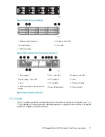
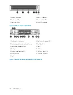

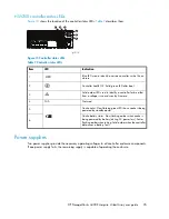


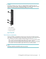


9. Enclosure power push button
1. Power supply 1
10. Power supply 2
2. HSV300 controller 1
11. Host ports, FP1, FP2, connection to front end (host or SAN)
3. Management module status LEDs
12. DP1–A port, back-end connection to A loop
4. Ethernet port
13. DP1–B port, back-end connection to B loop
5. Management module
14. Manufacturing diagnostic port
6. HSV300 controller 2
15. HSV300 controller status and fault LEDs
7. Rear UID push button
8. Enclosure status LEDs
Figure 11 HSV300 controller enclosure (back view)
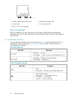
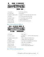
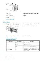
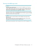
10. Power supply 2
1. Power supply 1
11. Switch ports, 1, 2, ... up to 10 for connection to front end
(switch or SAN)
2. HSV300–S controller 1
12. DPI-A port, back-end connection to A loop
3. Management module status LEDs
13. DPI-B port, back-end connection to B loop
4. Ethernet port
14. Console port (switch management), upper connection
5. Management module
15. Ethernet port (switch management)
6. HSV300–S controller 2
16. Manufacturing diagnostic port
7. Rear UID push button
17. HSV300–S controller status and fault LEDs
8. Enclosure status LEDs
9. Enclosure power push button
Figure 12 HSV300-S controller enclosure (back view)
HP StorageWorks 4400 Enterprise Virtual Array user guide
23
Summary of Contents for StorageWorks 4400
Page 10: ...10 ...
Page 36: ...EVA4400 hardware 36 ...
Page 48: ...EVA4400 operation 48 ...
Page 54: ...Replacing array components 54 ...
Page 92: ...Error messages 92 ...
Page 104: ...Regulatory notices 104 ...
Page 124: ...Glossary 124 ...
Page 128: ...128 ...


