background image

Connecting the Television Signal and Video Cables

45

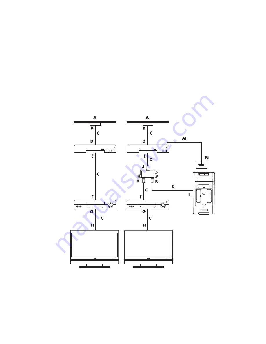
Wall to cable TV set-top box or satellite box to 
VCR to TV, using coaxial cable

1

Disconnect the coaxial cable from the input to the VCR, and connect it to the input of a 
coaxial cable signal splitter (not included; available at electronics stores).

2

Connect two coaxial cables to the splitter outputs.

3

Connect one of these cables to the input of the VCR, and the other cable to the TV 
connector on the back of the computer.

4

Connect the remote control sensor cable (emitter), and position it on the set-top box or 
satellite box. This enables the computer to change the channel on the box. See 
“Connecting the Remote Sensor.”

Setting up the computer with a splitter

Existing setup

A

Wall

B

Cable outlet

C

Coaxial cable

D

Set-top box/Satellite In

E

Set-top box/Satellite Out

F

VCR In

G

VCR Out

H

TV In

J

Splitter In

K

Splitter Out

L

TV In on back of computer

M

Remote control sensor cable

N

Remote control sensor

Summary of Contents for SR5410F - Compaq Presario - 1 GB RAM

Page 1: ...Advanced Setup Guide ...

Page 2: ...Copyright 2000 2007 Hewlett Packard Development Company L P This product incorporates copyright protection technology that is protected by U S patents and other intellectual property rights Use of this copyright protection technology must be authorized by Macrovision and is intended for home and other limited pay per view viewing uses only unless otherwise authorized by Macrovision Reverse enginee...

Page 3: ...ther Devices 10 Storing Documentation and Recovery Discs 10 Adjusting the Monitor 11 Adjusting the screen resolution by using Vista 11 Adjusting the screen resolution by using the NVIDIA Control Panel 11 Setting Up a Local Area Network 12 Setting Up a Wired Ethernet Connection 13 Integrated Wireless Devices 13 Connecting the Wireless LAN Device 14 Checking the wireless LAN device installation 15 U...

Page 4: ...onnecting the speakers 37 Connecting the FlexiJack connector 38 Connecting the Television Signal and Video Cables 39 Using TV Cables 39 Audio and Video Cables and Adapters 40 Connecting the TV Signal Source 41 Connecting a dual tuner 42 Connecting the Remote Sensor 43 Connecting the TV Signal Source When You Have an Existing Setup 44 Wall to VCR to TV using coaxial cable 44 Wall to cable TV set to...

Page 5: ...Connecting an HDMI device 53 Connecting a DVI device 54 Connecting to a Standard TV 55 Connecting to component video 55 Connecting to S video 56 Configuring the TV Tuner 56 Digital versus analog tuner 57 Initial configuration using Windows Media Center setup wizard 57 Changing the tuner settings 58 Index 59 ...

Page 6: ...vi Advanced Setup Guide features vary by model ...

Page 7: ... your new computer place it where ventilation openings are unobstructed Make sure that all connections are secure and that all cabling is out of the way Do not place cabling in walkways or where it can be stepped on or damaged from placing furniture on it WARNING The power supply is preset for the country region in which you purchased your computer If you move please check the voltage requirements...

Page 8: ...wer strips provide surge protection the power strip must be specifically labeled as having this capability Use a power strip whose manufacturer offers a damage replacement policy that replaces the equipment if surge protection fails Connecting to the computer Connect the main hardware devices such as the monitor keyboard and mouse to the back of the computer Other peripheral devices such as a prin...

Page 9: ...n Headphones Microphone FireWire IEEE 1394 for video cameras or other devices with very fast transfer rates NOTE You must use a 6 pin FireWire IEEE 1394 transfer cable with this 6 pin connector Digital audio in and digital audio out Side speaker out Rear speaker out Center Subwoofer Connector Icon Label Description and function continued ...

Page 10: ...the computer to record audio only select models only A V In Audio 2 R Secondary Right audio input connector red NOTE This Audio In connector is connected to the TV tuner You must use the Audio In connector which is connected to the motherboard and located on the back of the computer to record audio only select models only Headphones Out connector green to connect to headphones Microphone In connec...

Page 11: ...nect to a microphone also functions as a center subwoofer Line Out when a multichannel audio configuration is activated Audio Line Out green to connect front speakers Audio Line In blue connector to connect to an analog audio device such as a CD player for input into computer also functions as rear Line Out when a multichannel audio configuration is activated Center Line C Sub gold connector to co...

Page 12: ...puter select models only TV Cable Ant TV In TV antenna or cable input from wall outlet with no set top box ATSC TV In connector for TV cable or antenna which receives ATSC channels Advanced Television System Committee which are over the air digital transmission channels CATV TV In connector for TV cable or antenna which receives CATV Community Antenna Television or cable TV channels NTSC TV In con...

Page 13: ...a HDMI to DVI adapter to connect the display to the computer DVI Digital video output connector which connects to a TV or monitor select models only You may need to use a VGA to DVI or a HDMI to DVI adapter to connect the display to the computer See the documentation that came with the display device Digital audio input white connector which connects to a digital audio device with digital input su...

Page 14: ...n video camera transfer cable into the camera and then into an open port on the front or back of the computer Most digital video cameras use either the FireWire IEEE 1394 port or the USB port 3 A Found New Hardware message appears Wait 2 or 3 minutes for Windows Vista to make the necessary settings for the new device When installation is complete a message appears indicating that the camera is rea...

Page 15: ...e digital video camera 1 Click the Windows Start Button on the taskbar and then click Control Panel 2 Click System and Maintenance and then click System 3 Click Device Manager 4 Click the plus sign next to the camera port If the name of the camera appears the device is ready If the name is not there try the following Click Action and then click Scan for hardware changes Look in Device Manager for ...

Page 16: ...r handheld computers Refer to the documentation that came with your device Storing Documentation and Recovery Discs Store all computer user manuals and warranty information in an easy to find safe location It is a good idea to store the system recovery discs with the documentation This allows easy access to all important computer documents and files NOTE Some peripheral devices are not included wi...

Page 17: ...lick NVIDIA Control Panel 2 Select Standard or Advanced and then click OK 3 Under Display click Change resolution 4 If necessary select the display and then adjust the screen resolution by using the slider under Display resolution 5 Click Apply and then click Yes if you want to apply that resolution Or Click No and change the resolution by using the slider under Display resolution again click Appl...

Page 18: ...ers The network connection to the Internet is usually through a dial up or cable modem A wired network uses Ethernet cables to connect the devices on the network For example the Ethernet cable plugs into the computer network interface adapter and the router A wireless network uses radio waves to connect the devices on the network For example both the computer and the router have an antenna and ada...

Page 19: ...adio waves instead of wires Your computer may be equipped with one or more of the following integrated wireless devices Wireless local area network WLAN devices connect the computer to wireless local area networks commonly referred to as wireless networks wireless LANs or WLANs in corporate offices your home and public areas such as airports and restaurants In a WLAN each mobile wireless device co...

Page 20: ... 11n select models only 802 11b or 802 11g wireless network by using the external antenna that was included with the system This device enables you to establish a wireless network using the computer as a wireless access point or you can use the computer as a wireless client Station Mode if you already have a wireless network running You need an existing wireless LAN with an Internet connection con...

Page 21: ...n the taskbar click Help and Support and then type Setting up a wireless network into the Search Help box Go to http www hp com go techcenter wireless English only Go to http hp com support and search for wireless topics Using wireless security features When you set up a home WLAN or access an existing public WLAN always enable security features to protect the network from unauthorized access The ...

Page 22: ...16 Advanced Setup Guide features vary by model Connecting a Modem For information on connecting to the Internet see Connecting to the Internet in the Getting Started guide ...

Page 23: ...our channels for four speaker output or six channels for 5 1 speaker output Connect the speaker system to the computer and then configure the audio software for sound output Sound Connector Types Your model may include one of three analog sound connector types on the back of the computer Three connectors Six connectors Audio card The connectors are 3 5 mm 1 8 inch stereo mini jacks that connect fr...

Page 24: ...ound connector Illustration Type Three connectors Your computer model may include three sound connectors You can connect up to a 5 1 audio system to the computer 3 Six connectors Your computer model may include six sound connectors on the back of your computer You can connect up to a 7 1 audio system to the computer 6 Audio card connector Your computer may include a audio card You can connect up t...

Page 25: ...cts to a microphone Type 3 also functions as center subwoofer Line Out when a multichannel audio configuration is enabled Line In light blue connects to an analog audio device such as a CD player for input into computer Type 3 also functions as rear Line Out when a multichannel audio configuration is enabled Digital Audio Out or SPDIF Out orange connects to a digital audio device with digital inpu...

Page 26: ...ns You may set up your computer for two stereo speakers or for multichannel audio speaker systems Connect your speaker system to the computer and then configure the audio software for sound output For more details about connecting stereo speakers to the computer see the setup poster FlexiJack blue connects to analog Line In devices or a microphone The FlexiJack supports two functions You must sele...

Page 27: ...a subwoofer audio speakers 4 1 Two front speakers two rear speakers and a subwoofer Connecting 4 1 Four speakers and a subwoofer audio speakers 6 5 1 Two front speakers two rear speakers a center speaker and a subwoofer Connecting 5 1 Five speakers and a subwoofer audio speakers 8 7 1 Two front speakers two rear speakers two side speakers a center speaker and a subwoofer select models only Connect...

Page 28: ...o an eight speaker mode and uses two front speakers left right two side speakers left right two rear speakers left right a center speaker and a subwoofer Connecting 2 2 1 Two speakers and a subwoofer audio speakers To connect simple left right stereo active speakers or two speakers and a subwoofer for two channel 2 1 speaker output 1 Turn off the computer 2 Connect the speaker cable to the lime gr...

Page 29: ...r in the Getting Started guide Type S audio card See Using the Creative Sound Blaster X Fi or X Fi Fatality audio card in the Getting Started guide The following diagram shows a typical 2 1 audio installation Connecting 4 1 Four speakers and a subwoofer audio speakers To connect two front speakers two rear speakers and a subwoofer for four channel 4 1 speaker output 1 Turn off the computer 2 Conne...

Page 30: ...tem power 8 Turn on the speaker system 9 After the speakers are connected to the computer configure the audio software for sound output for your computer model See Configuring Speaker and Sound Options in the Getting Started guide Type 3 See Configuring speakers with Realtek HD Audio Manager in the Getting Started guide Type 6 See Configuring speakers with Realtek HD Audio Manager in the Getting S...

Page 31: ...e In connector functions as a Rear Line Out when a multichannel audio configuration is activated 4 Connect the center subwoofer speaker cable to the gold or pink Mic connector that matches the back of your computer For type 3 connector systems the pink Mic connector functions as a center subwoofer speaker Line Out when a multichannel audio configuration is activated 5 Connect the cables to the aud...

Page 32: ... Manager in the Getting Started guide Type 6 multistreaming See Configuring multistreaming audio in the Getting Started guide Type S audio card See Using the Creative Sound Blaster X Fi or X Fi Fatality audio card in the Getting Started guide The following diagram shows a typical 5 1 audio installation Connecting 7 1 Seven speakers and a subwoofer audio speakers Select models only To connect two f...

Page 33: ...Sub connector on the back of your computer 6 Connect the cables to the audio system 7 Connect the front rear side and center speakers to the subwoofer Refer to the speaker documentation 8 Turn on the computer 9 Connect the speaker system to the power 10 Turn on the speaker system 11 After the speakers are connected to the computer configure the audio software for sound output for your computer mod...

Page 34: ...atures vary by model The following diagram shows a typical 7 1 audio installation Color Description 1 Lime green Front audio input 2 Black Rear audio input 3 Orange Center subwoofer audio input 4 Gray Side audio input not shown ...

Page 35: ...arately The number of Y adapter cables that you need to connect to your home stereo system depends on the number of speakers that you install 2 2 1 speaker system One Y adapter cable 4 4 1 speaker system Two Y adapter cables 6 5 1 speaker system Three Y adapter cables 8 7 1 speaker system Four Y adapter cables Connecting a home stereo system to a computer requires audio cables that are long enough...

Page 36: ...tereo speakers and plugs into a home stereo standard left and right input This is only a suggested configuration Your system may be different Computer to 2 1 multichannel audio system connection A Computer back panel connectors type 3 type 6 or sound card B Y adapter cables C Receiver amplifier audio input jacks D Subwoofer E Front speakers left and right A B C E C D E ...

Page 37: ...r system may be different Computer to 5 1 multichannel audio system connection A Computer back panel connectors type 3 type 6 or sound card B Y adapter cables C Receiver amplifier audio input jacks D Subwoofer E Center speaker F Front speakers left and right G Rear speakers left and right 5 1 home audio installation procedure To connect a six channel 5 1 speaker home audio system to the computer 1...

Page 38: ... amplifier 5 If you have a center subwoofer speaker connect the stereo mini jack of a Y adapter cable into the microphone pink connector or the center speaker subwoofer gold connector that matches the back of your computer Connect the left and right ends of the Y adapter cable into the center subwoofer inputs on the back of the receiver amplifier 6 5 1 or higher channel system Plug the Y adapter c...

Page 39: ... Sound Blaster X Fi or X Fi Fatality audio card in the Getting Started guide 7 1 home audio installation The following diagram shows a typical advanced home theater system with an eight channel 8 7 1 speaker installation that requires multichannel inputs on a receiver amplifier This is only a suggested configuration Your system may be different Computer to 7 1 multichannel audio system connection ...

Page 40: ...nto the front left L and right R inputs on the back of the receiver amplifier 4 If you have rear speakers connect the rear stereo mini jack end of a Y adapter cable into the Audio Line In light blue or the Rear Speaker Out black connector on the back of your computer Connect the left and right ends of the Y adapter cable into the rear left L and right R inputs on the back of the receiver amplifier...

Page 41: ...nfigure the audio software for sound output for your computer model See Configuring Speaker and Sound Options in the Getting Started guide Type 3 See Configuring speakers with Realtek HD Audio Manager in the Getting Started guide Type 6 See Configuring speakers with Realtek HD Audio Manager in the Getting Started guide Type S audio card See Using the Creative Sound Blaster X Fi or X Fi Fatality au...

Page 42: ...eakers are connected to the computer configure the audio software for sound output for your computer model See Configuring Speaker and Sound Options in the Getting Started guide Audio card with digital output and type 3 connectors See Configuring speakers with Realtek HD Audio Manager in the Getting Started guide Follow the instructions to enable digital audio output Audio card with digital output...

Page 43: ... O Console the X Fi console is sold separately Line Out_3 orange or yellow 5 1 audio setup Front center subwoofer 6 1 audio setup Front center subwoofer and rear center 7 1 audio setup Front center subwoofer and side left Line Out_2 black 4 1 5 1 6 1 audio setup Rear left and right 7 1 audio setup Rear left rear right and side right Line Out_1 lime green 2 2 1 audio setup Front left and right Flex...

Page 44: ...teps in Configuring the FlexiJack connector in the Getting Started guide to configure the speaker settings in the Creative Sound Blaster X Fi software Connecting the FlexiJack connector The FlexiJack connector performs three functions Digital Input Output Line In Microphone You must select the function in the Creative Console Launcher NOTE If you are using the FlexiJack as your Digital In connecti...

Page 45: ...o the TV TV signal source video in to the computer Audio out from the computer to the TV TV signal source audio in to the computer NOTE Some graphic cards have a DVI connector and a DVI to VGA converter included in the box select models only If the monitor has a VGA connector but no DVI connector use the DVI to VGA converter to connect to the computer Connect the DVI to VGA converter to the DVI co...

Page 46: ...itor to an HDMI connector on the computer or connects an HDMI monitor to a DVI connector on the back of the computer This allows the graphic card driver to transfer HDMI signals to a monitor or a TV display Composite video cable RCA yellow end Plugs into an RCA connector such as Composite Video Out or TV Source In S video cable Y C 4 pin Plugs into an S video connector such as S video Video Out or...

Page 47: ...puter use an S video cable not provided or the composite video cable Plug the other end of the cable into the set top box or other device that is providing the signal source for the TV 2 If you are using a set top box with S video or composite video output plug audio cables not provided from the set top box into the Audio In right red connector and the Audio In left white connector on the back of ...

Page 48: ...cords another show on a different channel You can also record two different programs at the same time If you are using a TV antenna or standard cable connector the signal is routed to both tuners internally If you are using a cable or satellite set top box you must connect a second set of inputs Otherwise connect a second set top box to the second set of back panel connectors TV sources must be of...

Page 49: ... otherwise skip to step 3 If you have a second set top box you can also use connector 2 2 Remove the paper from the backing tape on the end of the cable B and then press the end of the cable over the remote infrared IR receiver window on the cable TV set top box C To locate the remote IR receiver window on the cable TV set top box use a flashlight to shine through the plastic on the front of most ...

Page 50: ...m the input to the VCR and connect it to the input of a coaxial cable signal splitter not included available at electronics stores 2 Connect two coaxial cables to the splitter outputs 3 Connect one of these cables to the input of the VCR and the other cable to the TV connector on the back of the computer Existing setup Setting up the computer with a splitter A Wall B Cable outlet C Coaxial cable D...

Page 51: ...bles to the input of the VCR and the other cable to the TV connector on the back of the computer 4 Connect the remote control sensor cable emitter and position it on the set top box or satellite box This enables the computer to change the channel on the box See Connecting the Remote Sensor Setting up the computer with a splitter Existing setup A Wall B Cable outlet C Coaxial cable D Set top box Sa...

Page 52: ... Or Connect one end of a composite video cable to a second output on the set top box or satellite box Connect the other end to the S video to composite video adapter cable and then connect the adapter to the S video In connector on the back of the computer 3 If you are using a composite video or S video cable you must also connect audio cables not included from the satellite box or set top box to ...

Page 53: ...outlet C Set top box Satellite In D Set top box Satellite Out E S video or composite cable F VCR In G VCR Out H TV In J Add an S video or composite cable with adapter K S video In on back of computer L Remote control sensor cable M Remote control sensor N Set top box second output O R Audio P L Audio ...

Page 54: ...eo connector you need a composite video cable Depending on the jacks on the back of the computer you may also need an S video adapter cable Connecting the computer to a TV 1 Turn off the computer 2 Connect the TV cable by doing one of the following depending on the connection connectors on the TV If the TV has an S video connector connect an S video cable A not included from the S video In connect...

Page 55: ...o enable the TV out option 1 Right click an empty area of the desktop and then click Personalize 2 Click Display Settings 3 If necessary select the monitor or TV 4 Click the Advanced button 5 Click the tab for the video card The tab may be labeled Displays ATI Displays Ge Force xxx nView or Devices 6 Choose the TV option and then follow the onscreen instructions Adjusting the screen resolution To ...

Page 56: ...k Next 5 Select the preferred display and then click Next 6 Select the display type and connection type for the TV display If you select the Composite or S video option Click Next which will take you to the screen to optimize the display Select the appropriate setting and then click Next When you have adjusted all the display settings click Finish this Wizard If you select DVI VGA or HDMI or Compo...

Page 57: ...and the computer 3 Remove the video and audio cables from the TV and the computer Connecting to a Monitor or High Definition TV Choosing the AV connection to use When you connect optional equipment as signal sources the connectors on the equipment may limit the type of connection that you can use When the optional equipment has more than one type of output connector choose the connection that prov...

Page 58: ...r playback from a digital DVD or DVR For more information see Connecting a DVI device Component video transmits video as separate red Pr green Y and blue Pb signals It is available in standard definition and high definition HD versions It delivers higher quality than S video and composite video connections Example A TV to a DVD player For more information see Connecting to component video S video ...

Page 59: ... sold separately To connect an HDMI device 1 Connect the HDMI cable to the HDMI connector on the computer There are no separate audio inputs for HDMI 2 Connect the cable to the HDMI device 3 Turn on the HDMI device and start play 4 Plug in the computer 5 Turn on the computer 6 In the TV Option menu define the HDMI Setup items Connector on the Computer ...

Page 60: ...nnect the HDMI end of the converter to the Digital Video connector on the computer and then connect the DVI cable to the DVI equipment Or If the computer has a DVI connector use a DVI video cable and connect the cable to the computer and to the DVI equipment 2 Connect the audio cables to the DVI equipment and to the computer 3 Turn on the DVI device and start play 4 Plug in the computer 5 Turn on ...

Page 61: ... 1 or Input 2 2 Connect the component audio cable to the left and right Audio connectors for the component input 3 Connect the cables to the component device 4 Turn on the device and start play 5 Plug in the computer 6 Turn on the computer NOTE Cables are sold separately WARNING In this example both Input 1 and Input 2 have both Component and Video connectors which share the left and right Audio c...

Page 62: ...edia Center setup wizard to configure or confirm the following settings on the computer Country region where the computer is being used Whether you want to receive analog or digital broadcasts you cannot receive both at the same time WARNING In this example Input 3 has both S video and Video connectors which share the left and right Audio connectors Connect only one video input for Input 3 NOTE In...

Page 63: ... stations may be available only in analog or digital You can use the procedure described in Initial configuration using Windows Media Center setup wizard step 5 to compare the stations that are available for each type of tuner Initial configuration using Windows Media Center setup wizard The first time that you start Windows Media Center the Windows Media Center setup wizard displays The Wizard co...

Page 64: ...guration steps until the list of stations for the new tuner type displays in the Scan for Stations window If you are satisfied with the stations that are listed click Next and complete the configuration by following the onscreen instructions If you are not satisfied with the stations that are listed return to step 6 and change back to the original tuner Changing the tuner settings Complete the fol...

Page 65: ...cable 40 Composite video connector 4 6 computer connecting the remote sensor 43 connecting the TV signal source 41 connecting TV signal source with set top box and VCR 45 front panel connectors 2 setting up 1 connecting devices 10 digital camera 8 digital video camera 8 dual tuner 42 DVI device 54 HDMI device 53 monitor 51 more than one display 49 peripherals 2 Standard TV 55 Standard video 55 S v...

Page 66: ... LAN device 15 connecting Ethernet LAN 5 connecting wireless LAN device 14 setting up 13 using Local Area Network 12 local area network LAN 12 M manuals storing 10 microphone connector 4 5 mini jack 17 modem connector 7 monitor adjusting 11 monitor connector 7 mouse connector 4 N network interface adapter 5 Network Interface Card NIC 13 P peripherals 2 power connector 4 printer connecting 10 conne...

Page 67: ...B connector 4 5 using coaxial cable 44 TV cables 39 your TV as a monitor 48 V video cables 39 40 videos working with home videos 8 W WEP 15 wired network connection 13 wireless devices 13 wireless LAN 14 wireless LAN connection 14 wireless local area network WLAN 13 wireless network security 15 wireless network device checking installation 15 wireless wide area networks WWAN devices 14 WLAN securi...

Page 68: ...Part number 5992 3574 ...

Reviews: