background image

3.

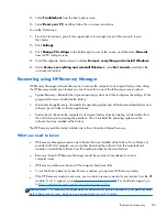
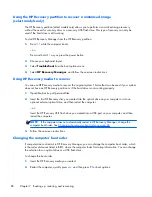
Select the optical drive or USB flash drive you want to boot from.

4.

Follow the on-screen instructions.

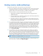
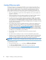
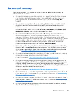
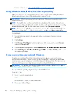
Removing the HP Recovery partition

HP Recovery Manager software allows you to remove the HP Recovery partition to free up hard

drive space.

IMPORTANT:

Removing the HP Recovery partition means you can no longer use Windows Refresh,

the Windows Remove everything and reinstall Windows option, or the HP Recovery Manager option

for minimized image recovery. Create HP Recovery media before removing the Recovery partition to

ensure you have recovery options; see 

Creating HP Recovery media on page 82

.

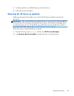
Follow these steps to remove the HP Recovery partition:

1.

From the Start screen, type 

recovery

, and then select 

HP Recovery Manager

.

2.

Select 

Remove Recovery Partition

, and then follow the on-screen instructions.

Restore and recovery

87

Summary of Contents for Split 13 x 2 PC

Page 1: ...HP Split 13 x2 PC Maintenance and Service Guide IMPORTANT This document is intended for HP authorized service providers only ...

Page 2: ...ition August 2013 Document Part Number 728979 002 Product notice This guide describes features that are common to most models Some features may not be available on your computer Not all features are available in all editions of Windows 8 This computer may require upgraded and or separately purchased hardware drivers and or software to take full advantage of Windows 8 functionality See for http www...

Page 3: ...w another hard surface such as an adjoining optional printer or a soft surface such as pillows or rugs or clothing to block airflow Also do not allow the AC adapter to contact the skin or a soft surface such as pillows or rugs or clothing during operation The device and the AC adapter comply with the user accessible surface temperature limits defined by the International Standard for Safety of Inf...

Page 4: ...iv Safety warning notice ...

Page 5: ...s 10 Lights 11 TouchPad 12 Left side 13 Right side 14 3 Illustrated parts catalog 15 Locating the serial number product number and model number 15 Tablet major components 16 Keyboard base major components 19 Cable Kit 21 Mass storage devices 22 Miscellaneous parts 23 Sequential part number listing 24 4 Removal and replacement preliminary requirements 29 Tools required 29 Service considerations 29 ...

Page 6: ...C battery 46 Volume button board 47 TouchScreen board 48 NFC module 49 Audio power connector board 51 Vibrator module 52 Docking connecter board 53 Display panel cable 55 Card reader board 56 Speakers 57 Wireless antennas 58 System board 60 Keyboard base component replacement procedures 63 Bottom cover 63 Keyboard base battery 65 TouchPad 67 Audio USB board 68 Power connector board 69 Hard drive 7...

Page 7: ... for quick and easy recovery 84 Remove everything and reinstall Windows 84 Recovering using HP Recovery Manager 85 What you need to know 85 Using the HP Recovery partition to recover a minimized image select models only 86 Using HP Recovery media to recover 86 Changing the computer boot order 86 Removing the HP Recovery partition 87 8 Power cord set requirements 88 Requirements for all countries 8...

Page 8: ...viii ...

Page 9: ...ED AntiGlare AG TouchScreen with MultiTouch enabled 16 9 wide aspect ratio typical brightness 400 nits slim 3 0 mm UWVA support for eDP 13 3 in 1366 768 HD LED AG TouchScreen with MultiTouch enabled 16 9 wide aspect ratio typical brightness 200 nits slim 3 0 mm support for eDP Memory Memory is non accessible upgradable Support for DDR3L 1600MHz dual channel 4 GB 1600 MHZ 1 35 v DDR3L 256 MB 16 8 p...

Page 10: ...m BCM4352 802 11ac 2 2 Wi Fi BT 4 0 Combo Adapter Intel Dual Band Wireless AC 7260 802 11 ac 2 2 WiFi BT 4 0 Combo Adapter Intel Wireless N 7260BN 802 11 b g n 2 2 WiFi BT 4 0 Combo Adapter Integrated wireless wide area network WWAN options by way of wireless module Two WLAN antennas built into tablet Support for the following WWAN formats HP hs3110 HSPA Mobile Broadband Module HP lt4112 LTE HPSA ...

Page 11: ...n at 60 Hz hot plug unplug and auto detection for correct output to wide aspect vs standard aspect video Keyboard pointing devices Full size island style keyboard no numerical keypad Clickpad with image sensor Clickpad requirements MultiTouch gestures enabled Taps enabled as default Power requirements Support for the following AC adapters 65 W HP Smart AC adapter non PFC 4 5 mm 65 W HP Smart AC ad...

Page 12: ...ck Device Manager A list reveals all the devices installed on your computer Locating software To find out what software is installed on your computer Mode Steps 1 From the Start screen right click using the mouse or Swipe from the top of the TouchPad to reveal all apps 2 Select the All apps icon 1 From the Start screen gently swipe your finger from the top edge or the bottom edge of the display be...

Page 13: ...eo conference and chat online using streaming video Swipe from the right edge of the TouchPad or TouchScreen to display the charms tap Search and then tap the search box type c and then select CyberLink YouCam from the list of applications or From the Start screen type c and then select Camera from the list of applications 5 Ambient light sensor The ambient light sensor automatically adjusts the d...

Page 14: ... keep the areas immediately around the antennas free from obstructions For wireless regulatory notices see the section of the Regulatory Safety and Environmental Notices that applies to your country or region To access this guide from the Start screen type support select the HP Support Assistant app select My computer and then select User guides 6 Chapter 2 External component identification ...

Page 15: ... stopped responding and Microsoft Windows shutdown procedures are ineffective press and hold the power button down for at least 5 seconds to turn off the tablet Swipe from the right edge of the TouchPad or TouchScreen to display the charms tap Search and then tap the search box In the search box type power select Settings and then select Power options or To learn more about your power settings on ...

Page 16: ...uter and then select User guides NOTE When a device is connected to the jack the computer speakers are disabled NOTE Be sure that the device cable has a 4 conductor connector that supports both audio out headphone and audio in microphone 3 Power connector Connects an AC adapter 4 Alignment post connectors 2 Align and attach the tablet to the keyboard base 5 Docking port power connector Connects th...

Page 17: ...tion 1 Alignment posts Align and attach the tablet to the keyboard base 2 Release latch Releases the tablet To release the tablet slide the release latch to the left 3 Docking connector Connects the tablet to the keyboard base Keyboard base 9 ...

Page 18: ...bination with the b key or the esc key select models only 3 Windows key Returns you to the Start screen from an open app or the Windows desktop NOTE Pressing the Windows key again will return you to the previous screen 4 Action keys Execute frequently used system functions NOTE Action keys do not display or function on the on screen keyboard of the tablet 10 Chapter 2 External component identifica...

Page 19: ...s lock is off 2 Mute light Amber Computer sound is off Off Computer sound is on 3 Wireless light On An integrated wireless device such as a WLAN device and or a Bluetooth device is on NOTE On some models the wireless light is amber when all wireless devices are off Keyboard base 11 ...

Page 20: ...finger gesture to move the pointer or activate items on the screen 2 Left TouchPad button Functions like the left button on an external mouse 3 Right TouchPad button Functions like the right button on an external mouse 12 Chapter 2 External component identification ...

Page 21: ...tion refer to the Regulatory Safety and Environmental Notices To access this guide from the Start screen type support select the HP Support Assistant app select My computer and then select User guides NOTE When a device is connected to the jack the computer speakers are disabled NOTE Be sure that the device cable has a 4 conductor connector that supports both audio out headphone and audio in micro...

Page 22: ...r audio device such as a high definition television any compatible digital or audio component or a high speed HDMI device 3 Power connector Connects an AC adapter 4 AC adapter light White The AC adapter is connected and the battery is charged Amber The AC adapter is connected and the battery is charging Off The computer is using battery power 14 Chapter 2 External component identification ...

Page 23: ... the serial number product number and model number You may need the information shown in the following illustration when you travel internationally or when you contact support Locating the serial number product number and model number 15 ...

Page 24: ...mbly cable is included in the Cable Kit spare part number 736883 001 See Cable Kit on page 21 for more Cable Kit spare part information 13 3 inch AG FHD WLED TouchScreen display assembly 737696 001 13 3 inch AG HD WLED TouchScreen display assembly 737697 001 2 RTC battery includes cable and double sided adhesive 740187 001 16 Chapter 3 Illustrated parts catalog ...

Page 25: ...c 2 2 WiFi BT 4 0 Combo Adapter 710661 006 Intel Wireless N 7260BN 802 11 b g n 2 2 WiFi BT 4 0 Combo Adapter 717384 006 7 Micro solid state drive mSSD 128 GB mSSD 737218 001 64 GB mSSD 737217 001 8 WWAN module HP hs3110 HSPA Mobile Broadband Module 723895 006 HP lt4112 LTE HPSA Mobile Broadband Module 740011 006 9 Power button board NOTE The power button board does not include the power button bo...

Page 26: ...art number 736883 001 See Cable Kit on page 21 for more Cable Kit spare part information 736886 001 14 Card reader board NOTE The card reader board does not include the card reader board cable The card reader board cable is included in the Cable Kit spare part number 736883 001 See Cable Kit on page 21 for more Cable Kit spare part information 736891 001 15 Docking connector board NOTE The docking...

Page 27: ...1 For use in Denmark Finland and Norway 737219 DH1 For use in France 737219 051 For use in Germany 737219 041 For use in Greece 737219 151 For use in Italy 737219 061 For use in Japan 737219 291 For use in Latin America 737219 161 For use in the Netherlands 737219 B31 For use in Portugal 737219 131 For use in Russia 737219 251 For use in Saudi Arabia 737219 171 Keyboard base major components 19 ...

Page 28: ...oes not include the power connector board cable The power connector board cable is included in the Cable Kit spare part number 736883 001 See Cable Kit on page 21 for more Cable Kit spare part information For use on keyboard base models equipped with a hard drive includes hard drive connector power connector HDMI port and USB port 736895 001 For use on keyboard base models not equipped with a hard...

Page 29: ...module cable 3 Power button board cable 4 Volume button board cable 5 TouchScreen board cable 6 NFC module cable 7 Audio power board cable 8 Docking connector board cable 9 Docking connector board cable 10 Digital card reader board cable 11 Display panel cable 12 TouchPad cable 13 Docking board ribbon cable Cable Kit 21 ...

Page 30: ...nclude hard drive bracket hard drive connector cable or screws 737957 005 Hard Drive Hardware Kit includes 731424 001 2a Hard drive bracket 2b Hard drive connector cable Screws not illustrated 3 Micro solid state drive mSSD 128 GB mSSD 737218 001 64 GB mSSD 737217 001 22 Chapter 3 Illustrated parts catalog ...

Page 31: ...For use in Denmark 490371 081 For use in Europe 490371 021 For use in Israel 490371 BB1 For use in Italy 490371 061 For use in Japan 490371 291 For use in North America 490371 001 For use in South Korea 490371 AD1 For use in Switzerland 490371 111 For use in Taiwan 490371 AB1 For use in Thailand 490371 201 For use in the United Kingdom and Singapore 490371 031 Rubber Kit includes 2 rear rubber fee...

Page 32: ... Power cord for use in India 3 pin black 1 83 m 701943 001 HP HDMI to VGA adapter 704927 001 HP RJ45 to USB adapter 710661 006 Intel Dual Band Wireless AC 7260 802 11 ac 2 2 WiFi BT 4 0 Combo Adapter 714657 001 65 W HP Smart AC adapter non PFC EM 4 5 mm 717384 006 Intel Wireless N 7260BN 802 11 b g n 2 2 WiFi BT 4 0 Combo Adapter 721092 001 45 W HP Smart AC adapter non PFC RC 4 5 mm 723895 006 HP ...

Page 33: ...ber 736883 001 See Cable Kit on page 21 for more Cable Kit spare part information 736890 001 Proximity sensor module NOTE The proximity sensor module does not include the proximity sensor module cable The proximity sensor module cable is included in the Cable Kit spare part number 736883 001 See Cable Kit on page 21 for more Cable Kit spare part information 736891 001 Card reader board NOTE The ca...

Page 34: ...r use in the United Kingdom and Singapore includes keyboard cable and TouchPad 737219 041 Keyboard top cover for use in Germany includes keyboard cable and TouchPad 737219 051 Keyboard top cover for use in France includes keyboard cable and TouchPad 737219 061 Keyboard top cover for use in Italy includes keyboard cable and TouchPad 737219 071 Keyboard top cover for use in Spain includes keyboard c...

Page 35: ...uipped with an Intel Core i3 4012Y 1 50 GHz processor 3 00 MB L3 cache dual core 4 5 W 4 GB of system memory a graphics subsystem with UMA memory and the Linux operating system includes replacement thermal material 738498 501 System board equipped with an Intel Core i3 4012Y 1 50 GHz processor 3 00 MB L3 cache dual core 4 5 W 4 GB of system memory a graphics subsystem with UMA memory and the Windo...

Page 36: ...ls not equipped with a hard drive includes power connector HDMI port and USB port NOTE The power connector board does not include the power connector board cable The power connector board cable is included in the Cable Kit spare part number 736883 001 See Cable Kit on page 21 for more Cable Kit spare part information 28 Chapter 3 Illustrated parts catalog ...

Page 37: ...some of the considerations that you must keep in mind during disassembly and assembly procedures NOTE As you remove each subassembly from the tablet place the subassembly and all accompanying screws away from the work area to prevent damage Plastic parts CAUTION Using excessive force during disassembly and reassembly can damage plastic parts Use care when handling the plastic parts Apply pressure ...

Page 38: ...d drive shut down the tablet If you are unsure whether the tablet is off or in Hibernation turn the tablet on and then shut it down through the operating system Before handling a drive be sure that you are discharged of static electricity While handling a drive avoid touching the connector Before removing a diskette drive or optical drive be sure that a diskette or disc is not in the drive and be ...

Page 39: ...e these precautions Keep components in their electrostatic safe containers until you are ready to install them Before touching an electronic component discharge static electricity by using the guidelines described in this section Avoid touching pins leads and circuitry Handle electronic components as little as possible If you remove a component place it in an electrostatic safe container The follo...

Page 40: ... proper materials are selected to avoid static charging When grounding is not possible use an ionizer to dissipate electric charges Workstation guidelines Follow these grounding workstation guidelines Cover the workstation with approved static shielding material Use a wrist strap connected to a properly grounded work surface and use properly grounded tools and equipment Use conductive field servic...

Page 41: ...m resistance between the operator and ground To be effective the conductive must be worn in contact with the skin The following grounding equipment is recommended to prevent electrostatic damage Antistatic tape Antistatic smocks aprons and sleeve protectors Conductive bins and other assembly or soldering aids Nonconductive foam Conductive tabletop workstations with ground cords of one megohm resis...

Page 42: ...es not include the display assembly cable The display assembly cable is included in the Cable Kit spare part number 736883 001 See Cable Kit on page 21 for more Cable Kit spare part information 13 3 inch AG FHD WLED TouchScreen display assembly 737696 001 13 3 inch AG HD WLED TouchScreen display assembly 737697 001 Before disassembling the tablet follow these steps 1 Turn off the tablet If you are...

Page 43: ...blet with the display screen facing down make sure the work surface is clear of tools screws and any other foreign objects Failure to follow this caution can result in damage to the display screen 4 Turn the tablet upside down with the docking connector power connector and audio connector toward you 5 Lift the bottom edge of the back cover 1 and then swing it up and back 2 until the left and right...

Page 44: ...he back cover see Back cover on page 34 WARNING To reduce potential safety issues use only the battery provided with the tablet a replacement battery provided by HP or a compatible battery purchased from HP CAUTION Removing a battery that is the sole power source for the tablet can cause loss of information To prevent loss of information save your work or shut down the tablet through Windows befor...

Page 45: ...age 21 for more Cable Kit spare part information 736890 001 Before removing the proximity sensor module follow these steps 1 Turn off the tablet If you are unsure whether the tablet is off or in Hibernation turn the tablet on and then shut it down through the operating system 2 Disconnect the power from the tablet by unplugging the power cord from the tablet 3 Disconnect all external devices from ...

Page 46: ...bcamera microphone module does not include the webcamera microphone module cable The webcamera microphone module cable is included in the Cable Kit spare part number 736883 001 See Cable Kit on page 21 for more Cable Kit spare part information 736900 001 Before removing the webcamera microphone module follow these steps 1 Turn off the tablet If you are unsure whether the tablet is off or in Hibern...

Page 47: ...le to the display assembly 2 Disconnect the webcamera microphone module cable 2 from the system board 3 Detach the webcamera microphone module 3 from the display assembly The webcamera microphone module is attached to the display assembly with double sided adhesive 4 Remove the webcamera microphone module and cable Reverse this procedure to install the webcamera microphone module Removal and repla...

Page 48: ...the power from the tablet by unplugging the power cord from the tablet 3 Disconnect all external devices from the tablet 4 Remove the back cover see Back cover on page 34 5 Remove the tablet battery see Tablet battery on page 36 Remove the solid state drive 1 Remove the Phillips PM2 0 3 0 screw 1 that secures the solid state drive to the system board The solid state drive tilts up 2 Remove the sol...

Page 49: ...down through the operating system 2 Disconnect the power from the tablet by unplugging the power cord from the tablet 3 Disconnect all external devices from the tablet 4 Remove the back cover see Back cover on page 34 5 Remove the tablet battery see Tablet battery on page 36 Remove the WLAN module 1 Disconnect the WLAN antenna cables 1 from the terminals on the WLAN module NOTE The WLAN antenna ca...

Page 50: ...e WLAN antenna cables are not connected to the terminals on the WLAN module protective sleeves should be installed on the antenna connectors as shown in the following illustration Reverse this procedure to install the WLAN module 42 Chapter 4 Removal and replacement preliminary requirements ...

Page 51: ...rd from the tablet 3 Disconnect all external devices from the tablet 4 Remove the back cover see Back cover on page 34 5 Remove the tablet battery see Tablet battery on page 36 Remove the WWAN module 1 Disconnect the WWAN antenna cables 1 from the terminals on the WWAN module NOTE The WWAN antenna cable labeled 5 connects to the WWAN module Main terminal labeled 5 The WWAN antenna cable labeled 6 ...

Page 52: ...e WWAN antenna cables are not connected to the terminals on the WWAN module protective sleeves should be installed on the antenna connectors as shown in the following illustration Reverse this procedure to install the WWAN module 44 Chapter 4 Removal and replacement preliminary requirements ...

Page 53: ...e operating system 2 Disconnect the power from the tablet by unplugging the power cord from the tablet 3 Disconnect all external devices from the tablet 4 Remove the back cover see Back cover on page 34 5 Remove the tablet battery see Tablet battery on page 36 Remove the power button board 1 Release the zero insertion force ZIF connector 1 to which the power button board cable is attached and then...

Page 54: ...y unplugging the power cord from the tablet 3 Disconnect all external devices from the tablet 4 Remove the back cover see Back cover on page 34 5 Remove the tablet battery see Tablet battery on page 36 Remove the RTC battery 1 Disconnect the RTC battery cable 1 from the system board 2 Detach the RTC battery 2 from the display assembly The RTC battery is attached to the display assembly with double...

Page 55: ...r in Hibernation turn the tablet on and then shut it down through the operating system 2 Disconnect the power from the tablet by unplugging the power cord from the tablet 3 Disconnect all external devices from the tablet 4 Remove the back cover see Back cover on page 34 5 Remove the tablet battery see Tablet battery on page 36 Remove the volume button board 1 Release the ZIF connector 1 to which t...

Page 56: ... 21 for more Cable Kit spare part information 736892 001 Before removing the TouchScreen board follow these steps 1 Turn off the tablet If you are unsure whether the tablet is off or in Hibernation turn the tablet on and then shut it down through the operating system 2 Disconnect the power from the tablet by unplugging the power cord from the tablet 3 Disconnect all external devices from the table...

Page 57: ...tall the TouchScreen board NFC module Description Spare part number NFC module includes double sided adhesive NOTE The NFC module does not include the NFC module cable The NFC module cable is included in the Cable Kit spare part number 736883 001 See Cable Kit on page 21 for more Cable Kit spare part information 736886 001 Before removing the NFC module follow these steps 1 Turn off the tablet If ...

Page 58: ... the NFC module ZIF connector 2 to which the NFC antenna cable is attached and then disconnect the NFC antenna cable from the NFC module 3 Detach the NFC module 3 from the display assembly The NFC module is attached to the display assembly with double sided adhesive 4 Remove the NFC module and cable Reverse this procedure to install the NFC module 50 Chapter 4 Removal and replacement preliminary r...

Page 59: ...nplugging the power cord from the tablet 3 Disconnect all external devices from the tablet 4 Remove the back cover see Back cover on page 34 5 Remove the tablet battery see Tablet battery on page 36 Remove the audio power connector board 1 Release the audio power connector board ZIF connector 1 to which the NFC module cable is attached and then disconnect the NFC module cable from the audio power ...

Page 60: ... If you are unsure whether the tablet is off or in Hibernation turn the tablet on and then shut it down through the operating system 2 Disconnect the power from the tablet by unplugging the power cord from the tablet 3 Disconnect all external devices from the tablet 4 Remove the back cover see Back cover on page 34 5 Remove the tablet battery see Tablet battery on page 36 Remove the vibrator modul...

Page 61: ...spare part number 736883 001 See Cable Kit on page 21 for more Cable Kit spare part information 736888 001 Before removing the docking connector board follow these steps 1 Turn off the tablet If you are unsure whether the tablet is off or in Hibernation turn the tablet on and then shut it down through the operating system 2 Disconnect the power from the tablet by unplugging the power cord from the...

Page 62: ...oard cable to the display assembly 4 Release the system board ZIF connector 4 to which the shorter docking connector board cable is attached and then disconnect the shorter docking connector board cable from the system board 5 Disconnect the Windows button board cable 5 from the docking connector board 6 Remove the two Phillips PM2 0 3 0 screws 6 that secure the docking connector board to the disp...

Page 63: ...ugging the power cord from the tablet 3 Disconnect all external devices from the tablet 4 Remove the back cover see Back cover on page 34 5 Remove the tablet battery see Tablet battery on page 36 Remove the display panel cable 1 Release the adhesive strip 1 that secures the display panel cable connector to the display assembly 2 Use the display panel cable connector bar 2 to disconnect the display...

Page 64: ...blet on and then shut it down through the operating system 2 Disconnect the power from the tablet by unplugging the power cord from the tablet 3 Disconnect all external devices from the tablet 4 Remove the back cover see Back cover on page 34 5 Remove the tablet battery see Tablet battery on page 36 Remove the card reader board 1 Release the system board ZIF connector 1 to which the card reader bo...

Page 65: ...ollow these steps 1 Turn off the tablet If you are unsure whether the tablet is off or in Hibernation turn the tablet on and then shut it down through the operating system 2 Disconnect the power from the tablet by unplugging the power cord from the tablet 3 Disconnect all external devices from the tablet 4 Remove the back cover see Back cover on page 34 and then remove the following components a T...

Page 66: ...bles and transceivers 736879 001 Before removing the wireless antenna cables and transceivers follow these steps 1 Turn off the tablet If you are unsure whether the tablet is off or in Hibernation turn the tablet on and then shut it down through the operating system 2 Disconnect the power from the tablet by unplugging the power cord from the tablet 3 Disconnect all external devices from the tablet...

Page 67: ...dule 2 Release the wireless antenna cables from the retention clips 2 and routing channel built into the display assembly 3 Detach the wireless antenna transceivers 3 from the display assembly The wireless antenna transceivers are attached to the display assembly with double sided adhesive Reverse this procedure to install the wireless antenna cables and transceivers Removal and replacement proced...

Page 68: ...he dual core 4 5 W and the Windows 8 1 Standard operating system 738498 501 Equipped with an Intel Core i3 4012Y 1 50 GHz processor 3 00 MB L3 cache dual core 4 5 W and the Linux operating system 738498 001 Before removing the system board follow these steps 1 Turn off the tablet If you are unsure whether the tablet is off or in Hibernation turn the tablet on and then shut it down through the oper...

Page 69: ...Docking connector board cable 5 Audio power connector board cable 6 Webcamera microphone module cable 7 Docking connector board cable 8 Display panel cable 9 Card reader board cable 10 Volume button board cable 11 RTC battery cable 2 Remove the three Phillips PM2 0 2 3 screws 1 that secure the system board to the display assembly Removal and replacement procedures 61 ...

Page 70: ...3 Remove the system board 2 Reverse this procedure to install the system board 62 Chapter 4 Removal and replacement preliminary requirements ...

Page 71: ...n Spare part number Bottom cover includes rubber feet 736882 001 Before disassembling the keyboard base follow these steps 1 Turn off the tablet and keyboard base If you are unsure whether the tablet and keyboard base are off or in Hibernation turn the tablet on and then shut it down through the operating system 2 Disconnect the power from the tablet and keyboard base by unplugging the power cord ...

Page 72: ...r to the keyboard top cover 4 Lift the rear edge of the bottom cover until the left and right sides detach from the keyboard top cover 5 Remove the bottom cover Reverse this procedure to install the bottom cover 64 Chapter 4 Removal and replacement preliminary requirements ...

Page 73: ... bottom cover see Bottom cover on page 63 WARNING To reduce potential safety issues use only the battery provided with the keyboard base a replacement battery provided by HP or a compatible battery purchased from HP CAUTION Removing a battery that is the sole power source for the tablet can cause loss of information To prevent loss of information save your work or shut down the tablet through Wind...

Page 74: ...4 Remove the keyboard base battery 4 Reverse this procedure to install the keyboard base battery 66 Chapter 4 Removal and replacement preliminary requirements ...

Page 75: ... tablet and keyboard base 3 Disconnect the tablet from the keyboard base 4 Remove the bottom cover see Bottom cover on page 63 5 Disconnect the keyboard base battery cable from the audio USB board see Keyboard base battery on page 65 Remove the TouchPad 1 Release the audio USB board ZIF connector 1 to which the TouchPad cable is attached and then disconnect the TouchPad cable from the audio USB bo...

Page 76: ...base 4 Remove the bottom cover see Bottom cover on page 63 5 Remove the keyboard base battery see Keyboard base battery on page 65 Remove the audio USB board 1 Release the power connector board ZIF connector 1 to which the audio USB board cable is attached and then disconnect the audio USB board cable from the power connector board 2 Release the audio USB board ZIF connector 2 to which the TouchPa...

Page 77: ...onnector HDMI port and USB port 736895 001 For use on keyboard base models not equipped with a hard drive includes power connector HDMI port and USB port 746493 001 Before removing the power connector board follow these steps 1 Turn off the tablet and keyboard base If you are unsure whether the tablet and keyboard base are off or in Hibernation turn the tablet on and then shut it down through the ...

Page 78: ...board to the keyboard top cover 3 Lift the right side of the power connector board and then swing it up 3 and to the left until it rests upside down on the right side of the keyboard top cover 4 Disconnect the hinge assembly cable 1 from the power connector board 5 Disconnect the hard drive cable 2 from the power connector board 6 Remove the power connector board 3 Reverse this procedure to instal...

Page 79: ...urn the tablet on and then shut it down through the operating system 2 Disconnect the power from the tablet and keyboard base by unplugging the power cord from the tablet and keyboard base 3 Disconnect the tablet from the keyboard base 4 Remove the bottom cover see Bottom cover on page 63 5 Remove the keyboard base battery see Keyboard base battery on page 65 6 Remove the power connector board see...

Page 80: ... hard drive perform the following steps a Disconnect the hard drive connector cable 1 from the hard drive b Remove the four Phillips PM2 75 4 0 screws 2 that secure the hard drive bracket to the hard drive 72 Chapter 4 Removal and replacement preliminary requirements ...

Page 81: ... these steps 1 Turn off the tablet and keyboard base If you are unsure whether the tablet and keyboard base are off or in Hibernation turn the tablet on and then shut it down through the operating system 2 Disconnect the power from the tablet and keyboard base by unplugging the power cord from the tablet and keyboard base 3 Disconnect the tablet from the keyboard base 4 Remove the bottom cover see...

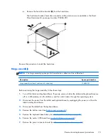
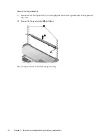
Page 82: ...ur Phillips PM2 0 3 0 screws 1 that secure the hinge assembly to the keyboard top cover 2 Remove the hinge assembly 2 and cables Reverse this procedure to install the hinge assembly 74 Chapter 4 Removal and replacement preliminary requirements ...

Page 83: ...ty BIOS Errors can prevent the computer from operating properly Updating the BIOS Updated versions of the BIOS may be available on the HP website Most BIOS updates on the HP website are packaged in compressed files called SoftPaqs Some download packages contain a file named Readme txt which contains information regarding installing and troubleshooting the file Determining the BIOS version To deter...

Page 84: ...led on your computer If the update is more recent than your BIOS make a note of the date name or other identifier You may need this information to locate the update later after it has been downloaded to your hard drive b Follow the on screen instructions to download your selection to the hard drive If the update is more recent than your BIOS make a note of the path to the location on your hard dri...

Page 85: ...cs UEFI tools in the following order a Connected USB drive NOTE To download the HP PC Hardware Diagnostics UEFI tool to a USB drive see Downloading HP PC Hardware Diagnostics UEFI to a USB device on page 77 b Hard drive c BIOS 2 Click the type of diagnostic test you want to run and then follow the on screen instructions NOTE If you need to stop a diagnostic test press esc Downloading HP PC Hardwar...

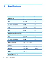
Page 86: ...ration 1 00 kg 2 21 lb Dimensions System tablet and keyboard base Width 34 00 cm 13 39 in Depth 23 00 cm 9 06 in Height 19 90 cm 0 78 in Weight lowest weight configuration 2 07 kg 4 56 lb Input power Operating voltage and current 19 5 V dc 2 31 A 45 W 19 5 V dc 3 33 A 65 W Temperature Operating 5 C to 35 C 41 F to 95 F Nonoperating 20 C to 60 C 4 F to 140 F Relative humidity non condensing Operati...

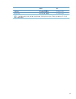
Page 87: ... to 3 048 m 50 ft to 10 000 ft Nonoperating 15 m to 12 192 m 50 ft to 40 000 ft NOTE Applicable product safety standards specify thermal limits for plastic surfaces The device operates well within this range of temperatures 79 ...

Page 88: ... even back to the original factory state all with simple steps This chapter provides information about the following processes Creating recovery media and backups Restoring and recovering your system NOTE This guide describes an overview of backing up restoring and recovering options For more details about the tools provided see Help and Support From the Start screen type h and then select Help an...

Page 89: ... time A system restore point contains information that Windows uses such as registry settings Windows creates a system restore point for you automatically during a Windows update and during other system maintenance such as a software update security scanning or system diagnostics You can also manually create a system restore point at any time For more information and steps for creating specific sy...

Page 90: ...rated optical drive with DVD writer capability but you would like to create DVD recovery media you can use an external optical drive purchased separately to create recovery discs or you can obtain recovery discs for your computer from the HP website For U S support go to http www hp com go contactHP For worldwide support go to http welcome hp com country us en wwcontact_us html If you use an exter...

Page 91: ...stem without losing your personal information settings or apps that came preinstalled on your computer or were purchased from the Windows Store consider using Windows Refresh This option does not require backing up data to another drive See Using Windows Refresh for quick and easy recovery on page 84 If you want to reset your computer to its original state Windows provides an easy way to remove al...

Page 92: ... to reveal the charms 2 Click Settings 3 Click Change PC settings in the bottom right corner of the screen and then select General from the PC settings screen 4 Scroll the right side choices down to display Refresh your PC without affecting your files 5 Under Refresh your PC without affecting your files select Get started and then follow the on screen instructions Remove everything and reinstall W...

Page 93: ...applications Factory Reset Restores the computer to its original factory state by deleting all information from the hard drive and re creating the partitions Then it reinstalls the operating system and the software that was installed at the factory The HP Recovery partition select models only allows Minimized Image Recovery What you need to know HP Recovery Manager recovers only software that was ...

Page 94: ...ot working properly 1 If possible back up all personal files 2 Insert the first HP Recovery disc you created into the optical drive on your computer or into an optional external optical drive and then restart the computer or Insert the HP Recovery USB flash drive you created into a USB port on your computer and then restart the computer NOTE If the computer does not automatically restart in HP Rec...

Page 95: ...use Windows Refresh the Windows Remove everything and reinstall Windows option or the HP Recovery Manager option for minimized image recovery Create HP Recovery media before removing the Recovery partition to ensure you have recovery options see Creating HP Recovery media on page 82 Follow these steps to remove the HP Recovery partition 1 From the Start screen type recovery and then select HP Reco...

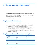
Page 96: ...t and no more than 2 0 m 6 5 ft All power cord sets must be approved by an acceptable accredited agency responsible for evaluation in the country or region where the power cord set will be used The power cord sets must have a minimum current capacity of 10 amps and a nominal voltage rating of 125 or 250 V AC as required by the power system of each country or region The appliance coupler must meet ...

Page 97: ... 15P 15 A 250 V configuration 3 The appliance coupler flexible cord and wall plug must bear a T mark and registration number in accordance with the Japanese Dentori Law The flexible cord must be Type VCT or VCTF 3 conductor 1 00 mm conductor size The wall plug must be a two pole grounding type with a Japanese Industrial Standard C8303 7 A 125 V configuration 4 The flexible cord must be Type RVV 3 ...

Page 98: ...in general household waste Follow the local laws and regulations in your area for battery disposal HP encourages customers to recycle used electronic hardware HP original print cartridges and rechargeable batteries For more information about recycling programs see the HP Web site at http www hp com recycle 90 Chapter 9 Recycling ...

Page 99: ...onents display 5 edge 7 keys 9 10 left side 13 lights 11 right side 14 TouchPad 12 connectors service considerations 30 D display assembly spare part numbers 16 27 display components 5 display panel cable illustrated 21 removal 55 display panel product description 1 docking connector 9 docking connector board removal 53 spare part number 18 25 53 docking port 8 drives preventing damage 30 E edge c...

Page 100: ...ton board removal 45 spare part number 17 25 45 power connector 8 14 power connector board removal 69 spare part numbers 20 26 28 69 power cord set requirements 88 spare part numbers 24 power requirements product description 3 processor product description 1 product description audio 2 chipset 1 display panel 1 Ethernet 2 external media cards 2 graphics 1 memory module 1 microphone 2 operating sys...

Page 101: ...le removal 52 spare part number 18 26 52 video product description 2 volume button 8 volume button board removal 47 spare part number 17 25 47 W webcamera light location 5 webcamera location 5 webcamera microphone module removal 38 spare part number 17 26 38 Windows button 6 Windows key 10 wireless antenna location 5 removal 58 spare part number 24 58 Wireless Antenna Kit spare part number 24 wire...

Page 102: ......

Reviews: