background image

Optional HP Retail RP7 VFD Customer Display

Description

Spare part number

VFD customer display, pole

702783-001

VFD customer display, bracket

702784-001

VFD customer display, cable kit (includes USB power cable and VFD cable)

702785-001

The integrated VFD customer display can be installed with no poles attached, or with one or two
poles attached, depending on the desired height of the VFD. There are two recommended
procedures for installing the VFD customer display: one procedure without poles attached and
another procedure with poles attached.

Installing the VFD Customer Display Without Poles

1.

Prepare the computer for disassembly (

Preparation for Disassembly on page 46

).

2.

Remove the rear I/O panel (

Rear I/O Panel on page 49

).

3.

Remove the power supply cover (

Power Supply Cover on page 47

).

4.

Remove the decorative panel (

Decorative Panel (IMD) on page 48

).

5.

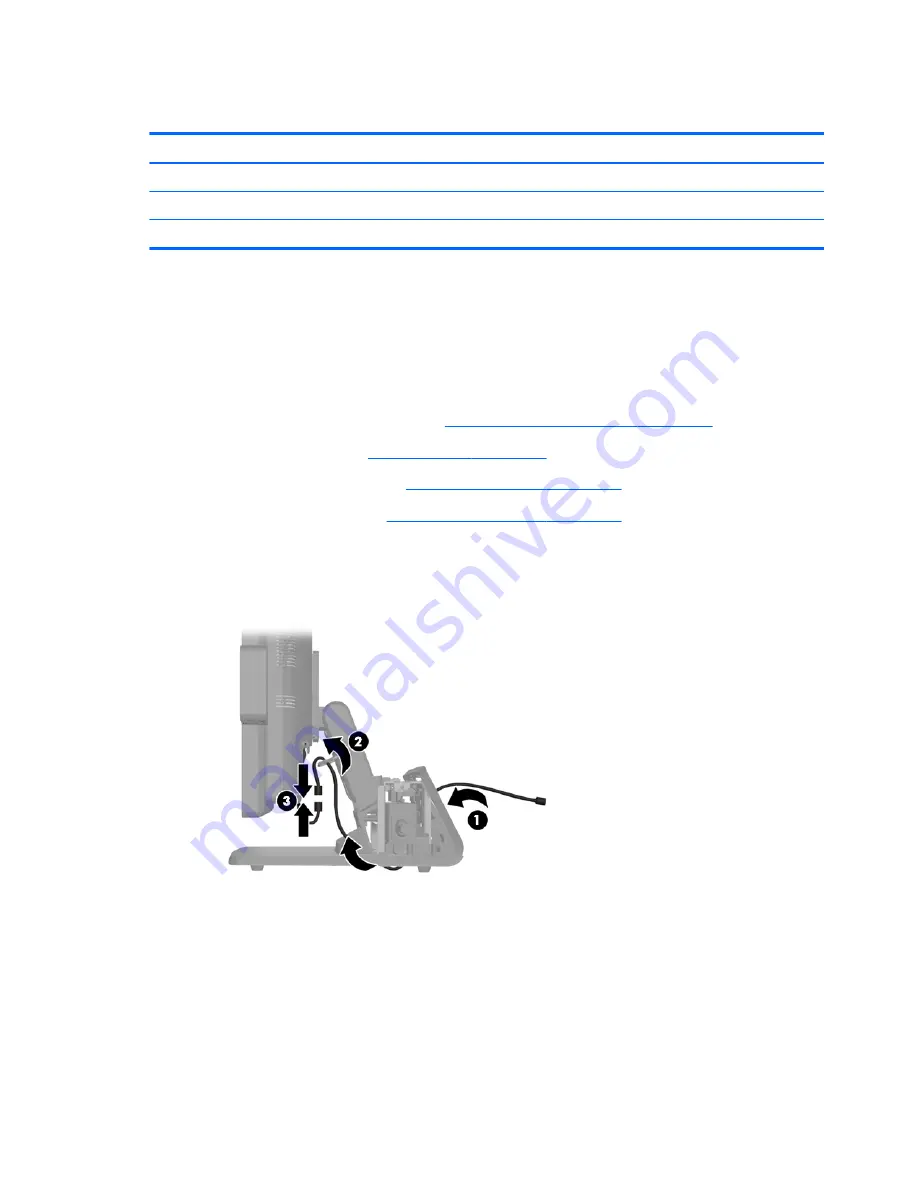
Route the VFD extension cable that was included with the VFD through the rear of the base and
out the front of the base 

(1)

, then though the cable retainer 

(2)

. Connect the extension cable to

the I/O cable included with the VFD 

(3)

 and connect the I/O cable to the 12V USB port on the

RP7.

72

Chapter 8   Removal and Replacement Procedures

Summary of Contents for RP7 Model 7800

Page 1: ...Maintenance Service Guide HP RP7 Retail System Model 7800 ...

Page 2: ...anty statements accompanying such products and services Nothing herein should be construed as constituting an additional warranty HP shall not be liable for technical or editorial errors or omissions contained herein This document contains proprietary information that is protected by copyright No part of this document may be photocopied reproduced or translated to another language without the prio...

Page 3: ...ollow directions could result in bodily harm or loss of life CAUTION Text set off in this manner indicates that failure to follow directions could result in damage to equipment or loss of information NOTE Text set off in this manner provides important supplemental information iii ...

Page 4: ...iv About This Book ...

Page 5: ... upgrading device drivers 8 Customizing the monitor display 8 3 Computer Setup F10 Utility 9 Computer Setup F10 Utilities 9 Using Computer Setup F10 Utilities 10 Computer Setup File 11 Computer Setup Storage 12 Computer Setup Security 13 Computer Setup Power 17 Computer Setup Advanced 18 Recovering the Configuration Settings 20 4 Computer Diagnostic Features 21 Hewlett Packard Vision Diagnostics 2...

Page 6: ...es 37 SATA Hard Drives 37 SATA Hard Drive Cables 38 SATA Data Cable 38 SATA Power Cable 38 ATA SMART Drives 39 Hard Drive Capacities 39 7 Routine Care and Disassembly Preparation 40 Electrostatic Discharge Information 40 Generating Static 40 Preventing Electrostatic Damage to Equipment 41 Personal Grounding Methods and Equipment 41 Grounding the Work Area 42 Recommended Materials and Equipment 42 ...

Page 7: ...l RP7 VFD Customer Display 72 Installing the VFD Customer Display Without Poles 72 VFD Customer Display With One or Two Poles 76 Cable Management 81 Memory 82 SODIMMs 82 82 DDR3 SDRAM DIMMs 82 Populating DIMM Sockets 83 Installing DIMMs 83 Hard Drive 86 Removing the Display Head from the Stand 90 Rear Metal Plate EMI shield 91 Battery 93 Blower 95 Heat Sink 97 Processor 99 Drive Cables and Bracket...

Page 8: ...uirements 119 Country Specific Requirements 120 Appendix D POST Error Messages 121 Power On Self Test POST 121 POST Numeric Codes and Text Messages 122 Interpreting POST Diagnostic Front Panel LEDs and Audible Codes 127 Appendix E Password Security and Resetting CMOS 130 Resetting the Password Jumper 131 Clearing and Resetting the CMOS 132 Appendix F Troubleshooting Without Diagnostics 134 Safety ...

Page 9: ...150 Solving hardware installation problems 152 Solving network problems 154 Solving memory problems 156 Solving processor problems 158 Solving USB flash drive problems 158 Solving internet access problems 159 Solving software problems 161 Index 162 ix ...

Page 10: ...x ...

Page 11: ...associate facing touchscreen 15 Resistive 15 Projective Capacitive 17 Projective Capacitive Cable management features Water and dust resistant touch screens Flexible use with display tilt and height adjustments Three optional peripherals that can be integrated HP Retail Integrated Dual Head MSR HP Retail Integrated Fingerprint Reader HP Retail Integrated Webcam Standard Features 1 ...

Page 12: ... mechanically only one can be used Processor choices DDR3 memory Operating system choices Integrated NIC WiFi some models USB PWR and cash drawer ports Hard drive and SSD choices RAID level 0 1 capable RAID 1 can be HP factory preconfigured Manageability tools Energy Star 5 qualified EU Compliant RoHS2 Compliant 87 energy efficient internal power supply adapter HP Limited Warranty 3 3 3 standard 3...

Page 13: ...P Retail Integrated Webcam 2 HP Retail RP7 VFD Customer Display 5 HP Retail Integrated Fingerprint Reader 3 HP Retail RP7 10 4 Customer Display 6 HP Retail Integrated Dual Head MSR NOTE A stand alone VFD that is mounted on a separate stand is also available from HP not pictured above Optional HP RP7 Accessories 3 ...

Page 14: ...e forward through the OSD menu and increase adjustment levels 4 OK If the OSD menu is on tap to select a menu item 5 Power LED Green Fully powered Flashing Green Sleep mode Red PC error condition refer to Interpreting POST Diagnostic Front Panel LEDs and Audible Codes on page 127 for more information Off Power is off 6 Power Button Powers the system on and off and sets the system to hibernate or s...

Page 15: ...select Save and Return or Cancel if you don t want to save the setting then select Exit from the Main Menu 8 To lock or unlock the OSD press and hold the Menu button for 10 seconds The following table lists the OSD Main menu items with a brief descriptions of each item Table 1 1 OSD Main Menu Icon Main Menu Description Brightness Adjusts the brightness level of the screen Contrast Adjusts the cont...

Page 16: ... 15 Cash Drawer Connector covered 8 Powered USB 24V NOTE The serial ports can be configured as 5V or 12V powered serial ports Refer to Configuring Powered Serial Ports on page 118 for more information NOTE The 24 volt Powered USB connector and the 12 volt Powered USB connector are keyed differently as a precaution to prevent connection errors NOTE You must peel off the metallic tape over the cash ...

Page 17: ...bove the monitor to permit the required airflow Installing the Windows operating system The first time you turn on the computer the operating system is installed automatically This process takes about 5 to 10 minutes Carefully read and follow the instructions on the screen to complete the installation CAUTION After the automatic installation has begun DO NOT TURN OFF THE COMPUTER UNTIL THE PROCESS...

Page 18: ...pted for the i386 directory replace the path specification with C i386 or use the Browse button in the dialog box to locate the i386 folder This action points the operating system to the appropriate drivers Obtain the latest support software including support software for the operating system from http www hp com support Select your country and language select Download drivers and software and fir...

Page 19: ...led suppresses most POST messages such as memory count product name and other non error text messages If a POST error occurs the error is displayed regardless of the mode selected To manually switch to Post Messages Enabled during POST press any key except F1 through F12 Establish an Ownership Tag the text of which is displayed each time the system is turned on or restarted Enter the Asset Tag or ...

Page 20: ... Setup 4 A choice of five headings appears in the Computer Setup Utilities menu File Storage Security Power and Advanced 5 Use the arrow left and right keys to select the appropriate heading Use the arrow up and down keys to select the option you want then press Enter To return to the Computer Setup Utilities menu press Esc 6 To apply and save changes select File Save Changes and Exit If you have ...

Page 21: ...with a BIOS image file located on removable media Replicated Setup Save to Removable Media Saves system configuration including CMOS to a formatted 1 44 MB diskette a USB flash media device or a diskette like device a storage device set to emulate a diskette drive Restore from Removable Media Restores system configuration from a diskette a USB flash media device or a diskette like device Default S...

Page 22: ...anged If the selected translation mode is not compatible with the translation mode that was active when the disk was partitioned and formatted the data on the disk will be inaccessible Default Values SATA Defaults See Translation Mode above for details Storage Options SATA Emulation WARNING SATA emulation changes may prevent access to existing hard drive data and degrade or corrupt established vol...

Page 23: ...has started Shortcut to Temporarily Override Boot Order To boot one time from a device other than the default device specified in Boot Order restart the computer and press F9 when the monitor light turns green After POST is completed a list of bootable devices is displayed Use the arrow keys to select the preferred bootable device and press Enter The computer then boots from the selected non defau...

Page 24: ...p Management Guide for more information Smart Cover some models Allows you to Lock unlock the Cover Lock Set the Cover Removal Sensor to Disable Notify User Setup Password NOTE Notify User alerts the user that the sensor has detected that the cover has been removed Default is disabled Device Security Allows you to set Device Available Device Hidden default is Device Available for Embedded security...

Page 25: ...er Boot Record Security Enables disables Master Boot Record Security Default is disabled The Master Boot Record MBR contains information needed to successfully boot from a disk and to access the data stored on the disk Master Boot Record Security may prevent unintentional or malicious changes to the MBR such as those caused by some viruses or by the incorrect use of certain disk utilities It also ...

Page 26: ...y defaults will erase all security keys Changing this setting requires turning the computer off and then back on Default is Do not reset CAUTION The embedded security device is a critical component of many security schemes Erasing the security keys will prevent access to data protected by the Embedded Security Device Choosing Reset to Factory Settings may result in significant data loss OS managem...

Page 27: ...attern Default is disabled S0 On Solid green LED S3 Stand By 3 blinks at 1Hz 50 duty cycle followed by a pause of 2 seconds green LED repeated cycles of 3 blinks and a pause S4 Hibernation 4 blinks at 1Hz 50 duty cycle followed by a pause of 2 seconds green LED repeated cycles of 4 blinks and a pause S5 Soft Off LED is off NOTE If this feature is disabled S4 and S5 both have the LED off S1 no long...

Page 28: ...er on automatically as soon as power is restored if it was on when power was lost NOTE If you turn off power to the computer using the switch on a power strip you will not be able to use the suspend sleep feature or the Remote Management features POST Delay in seconds Enabling this feature will add a user specified delay to the POST process This delay is sometimes needed for hard disks on some PCI...

Page 29: ...t affect external speakers Default is enabled NIC Option ROM Download PXE iSCSI disabled The BIOS contains an embedded NIC option ROM to allow the unit to boot through the network to a PXE server This is typically used to download a corporate image to a hard drive The NIC option ROM takes up memory space below 1MB commonly referred to as DOS Compatibility Hole DCH space This space is limited This ...

Page 30: ... set amount of time for a operating system and BIOS watchdog alert to be sent if the timers are not deactivated BIOS watchdog is deactivated by BIOS and would indicate that a halt occurred during execution if the alert is sent to the management console An operating system alert is deactivated by the operating system image and would indicate that a hang occurred during its initialization Default is...

Page 31: ... functioning properly Running tests is optional but recommended after installing or connecting a new device You should run tests save the test results and print them so that you have printed reports available before placing a call to the Customer Support Center NOTE Third party devices may not be detected by HP Vision Diagnostics Accessing HP Vision Diagnostics To access HP Vision Diagnostics you ...

Page 32: ...y default the View Level is set to Overview which displays general information about all of the component categories In the Category field you can select the following categories of information to display All Gives a listing of all categories of information about the computer Architecture Provides system BIOS and PCI device information Asset Control Shows product name system serial number asset ta...

Page 33: ...iagnostic software will prompt you for input during tests NOTE Memory can not be tested from within the HP Vision Diagnostics application To test the memory in your computer you must exit HP Vision Diagnostics boot to either the CD or USB flash drive and select HP Memory Test from the boot menu To begin testing 1 Select the Test tab 2 Select the type of tests you want to run Quick Complete or Cust...

Page 34: ...lays the tests for devices that have failed during the diagnostic testing and includes the following columns of information The Device section displays the device tested The Test section displays the type of test run The Times Failed is the number of times the device has failed a test The Defect Code provides a numerical code for the failure The error codes are defined in the Help tab The Descript...

Page 35: ... the hard drive The system will automatically create an html file that has the same appearance as the information displayed on the screen 1 Insert a USB flash drive if running HP Vision Diagnostics from CD 2 Click Save in the bottom on any of the Survey History or Errors tabs All three log files will be saved regardless of from which tab the Save button was clicked 3 Select the drive onto which yo...

Page 36: ... the bootable USB flash drive Protecting the Software To protect software from loss or damage you should keep a backup copy of all system software applications and related files stored on the hard drive See the operating system or backup utility documentation for instructions on making backup copies of data files 26 Chapter 4 Computer Diagnostic Features ...

Page 37: ...702787 001 3 USB cover plate xxxxxx 001 Power adapter 180 W does not include power cord 702778 001 In Mold Decoration IMD customizable covers 4 Panel with hole for bottom rear on models with VFD 702781 001 5 Panel without hole for bottom rear on models without VFD 702786 001 6 Top panel small for top rear of display 702770 001 Plastics 27 ...

Page 38: ...l material Intel Core i5 2400S processor 2 5 GHz 65W 640953 001 Intel Core i3 2120 processor 3 3 GHz 65W 638629 001 Intel Pentium Dual Core G850 processor 2 9 GHz 65W 655973 001 Intel Celeron G540 processor 2 5 GHz 665119 001 Drives Description Spare part number 320 GB 7200 rpm hard drive 639135 001 256 GB Solid State Drive SSD 661842 001 128 GB Solid State Drive SSD 665961 001 32 GB MLC Flash 2 5...

Page 39: ...ard 702775 001 3 WLAN module 802 11a b g n 652165 001 4 Heat sink includes replacement thermal material 702773 001 5 EMI shield metal plate display head 702780 001 6 USB security cover for secured USB port on I O panel 702779 001 7 Grommet hard drive 594220 001 Rubber foot and screw kit 702788 001 Misc parts 29 ...

Page 40: ...s Description Spare part number Cables 1 LED cable assembly 702777 001 2 Hard drive harness cable assembly 702776 001 3 Hood sensor 702772 001 4 Antenna kit 702771 001 30 Chapter 5 Illustrated parts catalog ...

Page 41: ...Accessories Accessories 31 ...

Page 42: ...y bracket 702784 001 7 Display customer facing CFD 10 4 inch 667837 001 Display associate facing AFD 15 inch capacitive 667839 001 Display associate facing AFD 15 inch non capacitive 667838 001 8 Display associate facing AFD 17 inch capacitive 667841 001 9 Bracket for HP Retail RP7 10 4 Customer Display 703269 001 10 Cable kit for HP Retail RP7 10 4 Customer Display includes USB A cable DC in cabl...

Page 43: ...VFD Display Kit Description Spare part number VFD Display Kit 695662 001 1 VFD customer display 2 Display bracket 3 Poles 2 4 IMD panel 5 Screws 6 Cable kit VFD Display Kit 33 ...

Page 44: ... 3 Stand 4 Cable kit Sequential part number listing Spare part number Description 594220 001 Grommet hard drive 638629 001 Intel Core i3 2120 processor 3 3 GHz 65W 639135 001 320 GB 7200 rpm hard drive 640953 001 Intel Core i5 2400S processor 2 5 GHz 65W 652165 001 WLAN module 802 11a b g n 34 Chapter 5 Illustrated parts catalog ...

Page 45: ...er to add security identification functions 690685 001 Retail integrated dual head magnetic stripe reader for card data read 695661 001 Retail integrated webcam for live video functions 695662 001 VFD Kit 695665 001 Stand alone VFD Kit 702769 001 Bucket cover and rear I O cover 702770 001 IMD top panel small for top rear of display 702771 001 Antenna kit 702772 001 Hood sensor 702773 001 Heat sink...

Page 46: ...01 VFD customer display bracket 702785 001 VFD customer display cable kit includes USB power cable and VFD cable 702787 001 Power supply cover 703269 001 Bracket for HP Retail RP7 10 4 Customer Display 36 Chapter 5 Illustrated parts catalog ...

Page 47: ...ower cable 15 Maximum data cable length 39 37 in 100 cm Data interface voltage differential 400 700 mV Drive voltages 3 3 V 5 V 12 V Jumpers for configuring drive N A Data transfer rate 3 0 Gb s SATA connectors on the system board are color coded to make identification easier SATA Identification Color Port Attachment Sequence Primary channel device 0 Dark blue SATA 0 1 Primary channel device 1 Lig...

Page 48: ... grounds and 4 transmit receive pins Pin Number Usage Device Plug Host Plug P1 Ground Ground Ground P2 A Transmit data Receive data P3 A Transmit data Receive data P4 Ground Ground Ground P5 B Receive data Transmit data P6 B Receive data Transmit data P7 Ground Ground Ground P2 and P3 differential signal pair P5 and P6 differential signal pair SATA Power Cable Pin Usage Notes Pin Usage Notes P1 V3...

Page 49: ...es the maximum usable size of a drive partition A drive partition is the largest segment of a drive that may be properly accessed by the operating system A single hard drive may therefore be subdivided into a number of unique drive partitions in order to make use of all of its space Because of the differences in the way that drive sizes are calculated the size reported by the operating system may ...

Page 50: ...onic device exposed to electrostatic discharge ESD may not appear to be affected at all and can work perfectly throughout a normal cycle The device may function normally for a while but it has been degraded in the internal layers reducing its life expectancy Networks built into many integrated circuits provide some protection but in many cases the discharge contains enough power to alter device pa...

Page 51: ...grounded surface before removing them from their container Always be properly grounded when touching a sensitive component or assembly Avoid contact with pins leads or circuitry Place reusable electrostatic sensitive parts from assemblies in protective packaging or conductive foam Personal Grounding Methods and Equipment Use the following equipment to prevent static electricity damage to equipment...

Page 52: ...materials such as ordinary plastic assembly aids and Styrofoam Use field service tools such as cutters screwdrivers and vacuums that are conductive Recommended Materials and Equipment Materials and equipment that are recommended for use in preventing static electricity include Antistatic tape Antistatic smocks aprons or sleeve protectors Conductive bins and other assembly or soldering aids Conduct...

Page 53: ...h a soft damp cloth as needed Using cleaning products may discolor or damage the finish Occasionally clean the air vents on all vented sides of the computer Lint dust and other foreign matter can block the vents and limit the airflow Touch Screen Maintenance Keep your display and touch sensor clean The touch sensor requires very little maintenance HP recommends that you periodically clean the glas...

Page 54: ... finish U S screws have a silver finish and are used on hard drives only CAUTION As each subassembly is removed from the computer it should be placed away from the work area to prevent damage Cables and Connectors Most cables used throughout the unit are flat flexible cables These cables must be handled with care to avoid damage Apply only the tension required to seat or unseat the cables during i...

Page 55: ... comes with the computer provides power to the real time clock and has a minimum lifetime of about three years See the appropriate removal and replacement chapter for the chassis you are working on in this guide for instructions on the replacement procedures WARNING This computer contains a lithium battery There is a risk of fire and chemical burn if the battery is handled improperly Do not disass...

Page 56: ...uter and any peripheral devices that are connected to it 4 Disconnect the power cord from the electrical outlet and then from the computer CAUTION Regardless of the power on state voltage is always present on the system board as long as the system is plugged into an active AC outlet You must disconnect the power cord to avoid damage to the internal components of the computer 5 Disconnect all perip...

Page 57: ... supply cover 702787 001 1 Prepare the computer for disassembly Preparation for Disassembly on page 46 2 Pull the power supply cover back then lift if up and off the unit To install the power supply cover reverse the removal procedure Power Supply Cover 47 ...

Page 58: ... 46 2 Remove the power supply cover Power Supply Cover on page 47 3 Remove the decorative panel on the rear of the unit by gently prying the panel away from the base at the tab locations on the top and sides of the panel as indicated below 1 Then pull the top of the panel away from the base 2 and push straight down on the panel to release the bottom tabs 3 To replace decorative panel reverse the r...

Page 59: ...9 001 1 Prepare the computer for disassembly Preparation for Disassembly on page 46 2 Slide down the two levers on the upper corners of the rear I O panel 1 and rotate the cover off 2 To remove the rear I O panel reverse the installation procedures Rear I O Panel 49 ...

Page 60: ...r disassembly Preparation for Disassembly on page 46 2 Remove the rear I O panel Rear I O Panel on page 49 3 Push inward on the tab at the bottom of the USB security cover 1 and rotate the bottom of the cover up 2 to remove it 4 Insert the USB device into the USB port 50 Chapter 8 Removal and Replacement Procedures ...

Page 61: ...device has a cable place the cable in the channel on the side of the security cover 6 If you want to secure the USB port remove the security screw from the inside of the rear I O panel and install the screw in the screw hole on the side of the USB security cover NOTE You must use a T 10 tamper resistant Torx screwdriver available from HP to install the security screw Using the USB Security Cover 5...

Page 62: ...he bottom of the cover into the slots on the bottom of the chassis 1 Then rotate the top of the I O cover up so that it snaps securely onto the chassis 2 8 Reconnect the power cord and press the power button 52 Chapter 8 Removal and Replacement Procedures ...

Page 63: ... computer for disassembly Preparation for Disassembly on page 46 2 Slide the stand s mounting bracket cover up and off the mounting bracket To remove the mounting bracket cover reverse the installation procedures Mounting Bracket Cover 53 ...

Page 64: ...sassembly on page 46 2 Remove the rear I O panel Rear I O Panel on page 49 3 Press inward on the buttons located near the bottom sides of the display head s back panel 1 then slide the back panel up and off the display head 2 To remove the display head back panel reverse the installation procedures 54 Chapter 8 Removal and Replacement Procedures ...

Page 65: ...ly Cover on page 47 3 Remove the decorative panel Decorative Panel IMD on page 48 4 Remove the rear I O panel Rear I O Panel on page 49 5 Attach the RP7 display head to the stand s mounting bracket by aligning the slots on the display head with the hooks on the mounting bracket and sliding the display down 1 Install the three screws included with the stand through the mounting bracket and into the...

Page 66: ... Rotate open the small door at the base of the power supply housing 1 and slide the power supply brick into the housing 2 NOTE To keep the power adapter from getting jammed make sure the rubber feet are pointed toward the display 56 Chapter 8 Removal and Replacement Procedures ...

Page 67: ...Insert the cord into the cable retainer clip next to the power port 3 and connect the cord to the DC In power port 9 Route the AC power cord through the bottom of the stand s base then through the cavity inside the base and connect the cord to the power supply brick Insert the cord into the cable retainer clip on the side of the base and connect the other end of the cord to an electrical outlet RP...

Page 68: ...orative panel back onto the rear of the base 11 Replace the power supply cover by lowering it down over the neck of the base then sliding it back until it snaps in place 58 Chapter 8 Removal and Replacement Procedures ...

Page 69: ...the bottom of the cover into the slots on the bottom of the chassis 1 Then rotate the top of the I O cover up so that it snaps securely onto the chassis 2 13 You can adjust the monitor stand height and tilt to a variety of positions RP7 Adjustable Stand 59 ...

Page 70: ... the computer 3 Remove the rear I O panel Rear I O Panel on page 49 4 Remove the power supply cover Power Supply Cover on page 47 5 Remove the decorative panel Decorative Panel IMD on page 48 6 Route the cables underneath the rear of the base then through the hole in the center of the base then up through the cable retainer on the neck of the stand and into the appropriate I O port CAUTION Be sure...

Page 71: ...e decorative panel back onto the rear of the base 8 Replace the power supply cover by lowering it down over the neck of the base then sliding it back until it snaps in place Routing Cables to External Devices 61 ...

Page 72: ...he bottom of the cover into the slots on the bottom of the chassis 1 Then rotate the top of the I O cover up so that it snaps securely onto the chassis 2 10 Reconnect the power cord and press the power button 62 Chapter 8 Removal and Replacement Procedures ...

Page 73: ...de of the display head NOTE If you are installing a webcam do not install it on the sides of the display head The webcam must be installed on top of the display head for proper video orientation NOTE These USB ports only support the USB modules listed above They do not support optical drives or hard drives The procedure for installing an integrated USB module is the same for all modules To install...

Page 74: ... location where you want to install the USB module NOTE There is a small fingernail slot in the center of the interior edge of the USB cover plate that can be used to help slide the cover plate off the unit 5 Pull the plug that is inserted in the USB port out of the port NOTE Some models do not have plugs in the USB ports 64 Chapter 8 Removal and Replacement Procedures ...

Page 75: ...he module back 1 and insert the USB connector on the module into the USB port 2 7 Install the two screws that were previously removed 1 and slide the cover plate on the module forward to cover the screws 2 Optional Integrated USB Modules 65 ...

Page 76: ...ar I O cover by placing the hooks on the bottom of the cover into the slots on the bottom of the chassis 1 Then rotate the top of the I O cover up so that it snaps securely onto the chassis 2 10 Reconnect the power cord and press the power button 66 Chapter 8 Removal and Replacement Procedures ...

Page 77: ... Prepare the computer for disassembly Preparation for Disassembly on page 46 2 Remove the rear I O panel Rear I O Panel on page 49 3 Remove the power supply cover Power Supply Cover on page 47 4 Remove the decorative panel Decorative Panel IMD on page 48 5 Connect the audio DVI USB and power cables to the customer display Insert the DVI cable into the retainer clip at the base of the display head ...

Page 78: ...he slots on the back of the display and sliding the back plate up 2 so that the screw holes on the back plate are aligned with the screw holes on the display Install the two screws to secure the back plate to the display 3 7 Slide the cable ends through the hole in the center of the decorative panel that was included with the customer display 68 Chapter 8 Removal and Replacement Procedures ...

Page 79: ...rear of the base and out the front of the base then up through the cable retainer on the neck of the RP7 stand and connect the cables to the RP7 I O ports 9 Snap the decorative panel onto the rear of the base Optional HP Retail RP7 10 4 Customer Display 69 ...

Page 80: ...e 1 and install the two screws included with the customer display into the screw holes on top of the mounting bracket 2 11 Replace the power supply cover by lowering it down over the neck of the base then sliding it back until it snaps in place 70 Chapter 8 Removal and Replacement Procedures ...

Page 81: ...m of the cover into the slots on the bottom of the chassis 1 Then rotate the top of the I O cover up so that it snaps securely onto the chassis 2 13 Reconnect the power cord and press the power button on both displays Optional HP Retail RP7 10 4 Customer Display 71 ...

Page 82: ...s attached and another procedure with poles attached Installing the VFD Customer Display Without Poles 1 Prepare the computer for disassembly Preparation for Disassembly on page 46 2 Remove the rear I O panel Rear I O Panel on page 49 3 Remove the power supply cover Power Supply Cover on page 47 4 Remove the decorative panel Decorative Panel IMD on page 48 5 Route the VFD extension cable that was ...

Page 83: ...ble around the hooks on the rear of the base 7 Insert the end of the extension cable through the hole in the decorative panel 1 and snap the decorative panel onto the rear of the base 2 Optional HP Retail RP7 VFD Customer Display 73 ...

Page 84: ...ough the center of the mounting bracket 1 and slide the VFD onto the mounting bracket 2 9 Lay the VFD face down on clean dry cloth and connect the VFD cable to the extension cable 74 Chapter 8 Removal and Replacement Procedures ...

Page 85: ...base 1 and install the two screws included with the VFD into the screw holes on top of the mounting bracket 2 11 Replace the power supply cover by lowering it down over the neck of the base then sliding it back until it snaps in place Optional HP Retail RP7 VFD Customer Display 75 ...

Page 86: ...is 2 13 Reconnect the power cord and press the power button VFD Customer Display With One or Two Poles 1 Prepare the computer for disassembly Preparation for Disassembly on page 46 2 Remove the rear I O panel Rear I O Panel on page 49 3 Remove the power supply cover Power Supply Cover on page 47 4 Remove the decorative panel Decorative Panel IMD on page 48 76 Chapter 8 Removal and Replacement Proc...

Page 87: ... then slide the VFD onto the pole assembly 3 6 Route the VFD extension cable through the hole in the decorative panel that was included with the VFD then through the rear of the base 1 and out the front of the base Continue to route the extension cable up through the cable retainer 2 and connect the extension cable to the I O cable included with the VFD 3 Connect the I O cable to the 12V USB port ...

Page 88: ...7 Wrap the excess extension cable around the hooks on the rear of the base 8 Snap the decorative plate onto the rear of the base 78 Chapter 8 Removal and Replacement Procedures ...

Page 89: ...base 1 and install the two screws included with the VFD into the screw holes on top of the mounting bracket 2 10 Replace the power supply cover by lowering it down over the neck of the base then sliding it back until it snaps in place Optional HP Retail RP7 VFD Customer Display 79 ...

Page 90: ...he bottom of the cover into the slots on the bottom of the chassis 1 Then rotate the top of the I O cover up so that it snaps securely onto the chassis 2 12 Reconnect the power cord and press the power button 80 Chapter 8 Removal and Replacement Procedures ...

Page 91: ...end can break the internal wires Never bend a SATA data cable tighter than a 30 mm 1 18 in radius Never crease a SATA data cable CAUTION When disconnecting cables always pull the connector NEVER pull on the cable Pulling on the cable could damage the cable System board connectors are color coded to make it easier to find the proper connection Cable PCA Designator Hard drive data SATA0 Dark Blue Ha...

Page 92: ...ible with DDR3U memory and if you plug DDR3U memory into the system board it can cause the physical damage to the SODIMM or invoke system malfunction For proper system operation the SODIMMs must be industry standard 204 pin unbuffered non ECC PC3 12800 DDR3 1600 MHz compliant 1 5 volt DDR3 SDRAM SODIMMs The DDR3 SDRAM SODIMMs must also support CAS latency 11 DDR3 1600 MHz 11 11 11 timing contain t...

Page 93: ...he slowest SODIMM in the system Installing DIMMs CAUTION You must disconnect the power cord and wait approximately 30 seconds for the power to drain before adding or removing memory modules Regardless of the power on state voltage is always supplied to the memory modules as long as the computer is plugged into an active AC outlet Adding or removing memory modules while voltage is present may cause...

Page 94: ...he to of the memory access door 1 and rotate the door open 2 5 To remove a SODIMM press outward on the two latches on each side of the SODIMM 1 then pull the SODIMM out of the socket 2 84 Chapter 8 Removal and Replacement Procedures ...

Page 95: ...into the socket 2 so that the latches lock it in place NOTE A memory module can be installed in only one way Match the notch on the module with the tab on the memory socket 7 Close the memory access door The computer should automatically recognize the additional memory the next time you turn on the computer Memory 85 ...

Page 96: ...ure to back up the data from the old drive so that you can transfer the data to the new drive 1 Prepare the computer for disassembly Preparation for Disassembly on page 46 2 Remove the rear I O panel Rear I O Panel on page 49 3 Remove the display head back panel Display Head Back Panel on page 54 4 Open the hard drive door 1 then grasp the pull tab on the side of the hard drive and pull the hard d...

Page 97: ...ur screws from the sides of the hard drive carrier 1 and lift the hard drive out of the carrier 2 6 Place the new hard drive into the carrier 1 and install the four screws into the sides of the carrier 2 Hard Drive 87 ...

Page 98: ...the hard drive carrier assembly into the drive bay 1 and close the hard drive door 2 8 Slide the display head s back panel down onto the rear of the display head 88 Chapter 8 Removal and Replacement Procedures ...

Page 99: ...ng the hooks on the bottom of the cover into the slots on the bottom of the chassis 1 Then rotate the top of the I O cover up so that it snaps securely onto the chassis 2 10 Reconnect the power cord and press the power button Hard Drive 89 ...

Page 100: ...ing Bracket Cover on page 53 4 Remove the display head back panel Display Head Back Panel on page 54 5 Remove the RP7 display head from the stand by removing the three screws that attach the stand s mounting bracket to the display head 1 then slide the display up and off the mounting bracket 2 To remove the display head back panel reverse the installation procedures 90 Chapter 8 Removal and Replac...

Page 101: ...age 49 3 Remove the mounting bracket cover Mounting Bracket Cover on page 53 4 Remove the display head back panel Display Head Back Panel on page 54 5 Remove the display head from the stand Removing the Display Head from the Stand on page 90 6 Open the memory access door 1 disconnect the DisplayPort power cable 2 and signal cable 3 then swing the antenna bracket out away from the chassis 4 Rear Me...

Page 102: ...crews that secure the metal plate on the back of the display head 1 and lift the metal plate off the display head 2 To install the rear metal plate reverse the removal procedures 92 Chapter 8 Removal and Replacement Procedures ...

Page 103: ...ectronic components of the computer or optional equipment Before beginning these procedures ensure that you are discharged of static electricity by briefly touching a grounded metal object NOTE The lifetime of the lithium battery can be extended by plugging the computer into a live AC wall socket The lithium battery is only used when the computer is NOT connected to AC power HP encourages customer...

Page 104: ... the same orientation and pull the battery out of its holder 9 Insert the new battery Ensure that the positive side of the new battery is oriented in the same direction as the battery that was removed 10 Reverse the removal procedures 94 Chapter 8 Removal and Replacement Procedures ...

Page 105: ...ove the display head back panel Display Head Back Panel on page 54 5 Remove the display head from the stand Removing the Display Head from the Stand on page 90 6 Remove the rear metal plate Rear Metal Plate EMI shield on page 91 7 Remove the three Torx screws 1 that secure the blower to the computer 8 Disconnect the blower control cable from the system board connector labeled CPUFAN 2 Figure 8 1 R...

Page 106: ...y Figure 8 2 Swinging the antenna bracket out of the way 10 Lift the blower straight up and out of the chassis Figure 8 3 Removing the blower To install the blower reverse the removal procedures 96 Chapter 8 Removal and Replacement Procedures ...

Page 107: ... on page 49 3 Remove the mounting bracket cover Mounting Bracket Cover on page 53 4 Remove the display head back panel Display Head Back Panel on page 54 5 Remove the display head from the stand Removing the Display Head from the Stand on page 90 6 Remove the rear metal plate Rear Metal Plate EMI shield on page 91 7 Loosen the four captive screws that secure the heat sink to the system board Figur...

Page 108: ... Figure 8 5 Removing the heat sink When reinstalling the heat sink make sure that its bottom has been cleaned with an alcohol wipe and fresh thermal grease has been applied to the top of the processor CAUTION Tighten heat sink retaining screws in the order stamped on the heat sink 98 Chapter 8 Removal and Replacement Procedures ...

Page 109: ...er on page 53 4 Remove the display head back panel Display Head Back Panel on page 54 5 Remove the display head from the stand Removing the Display Head from the Stand on page 90 6 Remove the rear metal plate Rear Metal Plate EMI shield on page 91 7 Remove the heat sink Heat Sink on page 97 8 Rotate the locking lever to its full open position 1 9 Raise and rotate the microprocessor retainer to its...

Page 110: ...tem board always update the system ROM to ensure that the latest version of the BIOS is being used on the computer The latest system BIOS can be found on the Web at http h18000 www1 hp com support files 100 Chapter 8 Removal and Replacement Procedures ...

Page 111: ... 4 Remove the display head back panel Display Head Back Panel on page 54 5 Remove the display head from the stand Removing the Display Head from the Stand on page 90 6 Remove the rear metal plate Rear Metal Plate EMI shield on page 91 7 Remove the drive data cables from the clips on the cage 1 8 Remove the antenna cables from the clip on the cage 2 9 Remove the Torx screw 3 that secures the cage t...

Page 112: ...rd 11 Remove the drive cage and cable assembly from the computer 12 Remove the two Torx screws that secure the drive connector to the cage remove the wires from the slots in the cage and then remove the drive connector from the cage Figure 8 9 Removing the connector 102 Chapter 8 Removal and Replacement Procedures ...

Page 113: ...to the cage remove the cable from the clip on the cage and then remove the drive connector from the cage Figure 8 10 Removing the drive connector To reinstall the drive cable and bracket assembly reverse the removal procedure Drive Cables and Bracket Assembly 103 ...

Page 114: ...racket Cover on page 53 4 Remove the display head back panel Display Head Back Panel on page 54 5 Remove the display head from the stand Removing the Display Head from the Stand on page 90 6 Remove the rear metal cover Rear Metal Plate EMI shield on page 91 7 Disconnect the cable from the system board connector labeled HSENSE 1 8 Remove the cable from the clip on top of the serial port board 2 104...

Page 115: ...are the computer for disassembly Preparation for Disassembly on page 46 2 Remove the rear I O panel Rear I O Panel on page 49 3 Remove the mounting bracket cover Mounting Bracket Cover on page 53 4 Remove the display head back panel Display Head Back Panel on page 54 5 Remove the display head from the stand Removing the Display Head from the Stand on page 90 6 Remove the rear metal plate Rear Meta...

Page 116: ...om the routing path 2 9 Remove the cable from the clips 3 10 Lift the LED from the holder and remove the assembly from the computer 4 Figure 8 12 Removing the hard drive LED cable To reinstall the hard drive LED cable reverse the removal procedure 106 Chapter 8 Removal and Replacement Procedures ...

Page 117: ...4 5 Remove the display head from the stand Removing the Display Head from the Stand on page 90 6 Remove the rear metal plate Rear Metal Plate EMI shield on page 91 7 Remove the two Phillips screws 1 that secure the speaker to the computer 8 Remove the cable from the clip 2 9 Disconnect the cable from the system board connector labeled SPKR 3 Figure 8 13 Removing the speaker 10 Remove the speaker f...

Page 118: ...the display head from the stand Removing the Display Head from the Stand on page 90 6 Remove the rear metal plate Rear Metal Plate EMI shield on page 91 7 Remove the hood sensor cable from the clip on top of the card 1 8 Remove the two Torx screws 2 that secure the card to the system board 9 Lift the card straight up to disconnect it from the system board connector 3 and then remove it from the co...

Page 119: ...play Head Back Panel on page 54 5 Remove the display head from the stand Removing the Display Head from the Stand on page 90 6 Remove the rear metal plate Rear Metal Plate EMI shield on page 91 7 Remove the antenna cables from the connectors on the WLAN module 1 8 Remove the Phillips screw 2 that secures the module to the system board 9 Rotate the top of the module upward 3 and then pull it away f...

Page 120: ... on page 109 Processor Processor on page 99 Heat sink Heat Sink on page 97 Processor Processor on page 99 3 Remove the rear I O panel Rear I O Panel on page 49 4 Remove the mounting bracket cover Mounting Bracket Cover on page 53 5 Remove the display head back panel Display Head Back Panel on page 54 6 Remove the display head from the stand Removing the Display Head from the Stand on page 90 7 Rem...

Page 121: ...10 Lift the system board up and out of the chassis Figure 8 16 Removing the system board To install the system board reverse the removal procedure System Board 111 ...

Page 122: ...stem Restore to return the computer to a previous restore point You can also set restore points manually NOTE Always use this System Restore procedure before you use the System Recovery feature NOTE Some features might not be available on systems that are shipped without a Windows operating system To start System Restore 1 Close all open programs 2 Click the Start button right click Computer and t...

Page 123: ...ng on page 114 Recovery media Run System Recovery from recovery media that you have created from files stored on your hard disk drive or purchased separately To create recovery media see System recovery using recovery media on page 114 System Recovery when Windows is responding CAUTION System Recovery deletes all data and programs you created or installed Before you begin back up any important dat...

Page 124: ...elp immediately click System Recovery 6 If you are prompted to back up your files and you have not done so select Back up your files first recommended and then click Next Otherwise select Recover without backing up your files and then click Next 7 System Recovery begins After System Recovery is complete click Finish to restart the computer 8 When Windows has loaded shut down the computer reconnect...

Page 125: ...cs in a secure place To create a recovery USB flash drive NOTE You must use a flash drive with a capacity of at least 8 GB 1 Close all open programs 2 Insert the USB flash drive into a USB port on the computer 3 Click the Start button click All Programs click Security and Protection and then click Recovery Media Creation 4 Click Create recovery media with a USB flash drive and then click Next 5 Se...

Page 126: ...the arrow keys to select the boot menu and press Enter Use the arrow keys to select the location where the recovery media is inserted USB or DVD Press Enter to boot from that device 6 If Recovery Manager asks if you want to run System Recovery from Media or Hard Drive select Media On the Welcome screen under I need help immediately click Factory Reset 7 If you are prompted to back up your files an...

Page 127: ... the Calibrate the screen for pen or touch input link In the Tablet PC Settings dialog box tap the Calibrate button then proceed to step 2 2 Follow the on screen instructions to press the target marks on the touch screen At the end of the calibration process the touch module should be aligned with the video and the touch points will be accurate Calibration for Windows XP You must load the touch sc...

Page 128: ... a powered serial port If the serial port is configured as a powered port devices that support a powered serial interface do not require an external power source NOTE The computer ships with all serial ports configured in standard serial mode by default unless the powered serial port AV numbers are ordered The serial ports can be configured using the Computer F10 Setup utility Under the Onboard De...

Page 129: ...onsible for evaluation in the country where the power cord set will be installed 2 The power cord set must have a minimum current capacity of 10A 7A Japan only and a nominal voltage rating of 125 or 250 volts AC as required by each country s power system 3 The diameter of the wire must be a minimum of 0 75 mm2 or 18AWG and the length of the cord must be between 1 8 m 6 feet and 3 6 m 12 feet 4 A C...

Page 130: ... fittings appliance coupler and wall plug must bear the certification mark of the agency responsible for evaluation in the country where it will be used 2 The flexible cord must be Type SVT or equivalent No 18 AWG 3 conductor The wall plug must be a two pole grounding type with a NEMA 5 15P 15A 125V or NEMA 6 15P 15A 250V configuration 3 Appliance coupler flexible cord and wall plug must bear a T ...

Page 131: ...does not run all of the system level tests such as the memory test Full Boot runs all of the ROM based system tests and takes longer to complete Full Boot may also be enabled to run every 1 to 30 days on a regularly scheduled basis To establish the schedule reconfigure the computer to the Full Boot Every x Days mode using Computer Setup NOTE For more information on Computer Setup see the Computer ...

Page 132: ...ROMs Recently added PCI expansion card contains an option ROM too large to download during POST 1 If a PCI expansion card was recently added remove it to see if the problem remains 2 In Computer Setup set Advanced Device Options NIC PXE Option ROM Download to DISABLE to prevent PXE option ROM for the internal NIC from being downloaded during POST to free more memory for an expansion card s option ...

Page 133: ... memory has been added test using HP only memory 4 Verify proper memory module type 201 Memory Error RAM failure 1 Run Computer Setup or Windows utilities 2 Ensure memory modules are correctly installed 3 Verify proper memory module type 4 Remove and replace the identified faulty memory module s 5 If the error persists after replacing memory modules replace the system board 213 Incompatible Memory...

Page 134: ...ned to parallel port X 1 Remove any parallel port expansion cards 2 Clear CMOS 3 Reconfigure card resources and or run Computer Setup 410 Audio Interrupt Conflict IRQ address conflicts with another device Enter Computer Setup and reset the IRQ in Advanced Onboard Devices 411 Network Interface Card Interrupt Conflict IRQ address conflicts with another device Enter Computer Setup and reset the IRQ i...

Page 135: ...nt audio harness has been detached or unseated from motherboard Reconnect or replace front audio harness 918 Front USB Not Connected Front USB harness has been detached or unseated from motherboard Reconnect or replace front USB harness 921 Device in PCI Express slot failed to initialize There is an incompatibility problem with this device and the system or PCI Express Link could not be retrained ...

Page 136: ... For three devices use SATA 0 SATA1 and SATA 2 1797 SATA Drivelock is not supported in RAID mode Drivelock is enabled on one or more SATA hard drives and they cannot be accessed while the system is configured for RAID mode Either remove the Drivelocked SATA device or disable the Drivelock feature To disable the Drivelock feature enter Computer Setup change Storage Storage Options SATA Emulation to...

Page 137: ...ated with them WARNING When the computer is plugged into an AC power source voltage is always applied to the system board To reduce the risk of personal injury from electrical shock and or hot surfaces be sure to disconnect the power cord from the wall outlet and allow the internal system components to cool before touching NOTE If you see flashing LEDs on a PS 2 keyboard look for flashing LEDs on ...

Page 138: ...cond pause Beeps stop after fifth iteration but LEDs continue until problem is solved 4 Power failure power supply is overloaded 1 Ensure the DC power cable is plugged into the I O panel 2 Check if a device is causing the problem by removing ALL attached devices such as a hard drive Power on the system If the system enters the POST then power off and replace the device to see if the problem is res...

Page 139: ...econd pause Beeps stop after fifth iteration but LEDs continue until problem is solved 9 System powers on but is unable to boot 1 Replace the processor 2 Replace the system board Power LED flashes 12 times once every second followed by a two second pause Beeps stop after third iteration and the computer reboots 12 Health timer expired None System does not power on and LEDs are not flashing None Sy...

Page 140: ...oth passwords only the setup password will give you access to Computer Setup When both passwords are set the setup password can also be used in place of the power on password as an override to log in to the computer This is a useful feature for a network administrator If you forget the password for the computer you can clear that password so you can gain access to the information on the computer b...

Page 141: ...ronic components of the computer or optional equipment Before beginning these procedures ensure that you are discharged of static electricity by briefly touching a grounded metal object See the Safety Regulatory Information guide for more information 3 Remove the access panel 4 Locate the header and jumper labeled E49 on the system board NOTE The password jumper is green so that it can be easily i...

Page 142: ...utlet and allow the internal system components to cool before touching CAUTION When the computer is plugged in the power supply always has voltage applied to the system board even when the unit is turned off Failure to disconnect the power cord can result in damage to the system Static electricity can damage the electronic components of the computer or optional equipment Before beginning these pro...

Page 143: ...r system board components see the Illustrated Parts Service Map IPSM for that particular system 6 Close the memory door and replace the rear cover 7 Reconnect the external devices 8 Plug in the computer and turn on power NOTE You will receive POST error messages after clearing CMOS and rebooting advising you that configuration changes have occurred Use Computer Setup to reset any special system se...

Page 144: ...tions below to try to isolate the exact problem before calling for technical support Run the HP diagnostic tool Run the hard drive self test in Computer Setup Refer to Computer Setup F10 Utility on page 9 for more information Check the Power LED on the front of the computer to see if it is flashing red The flashing lights are error codes that will help you diagnose the problem Refer to Appendix A ...

Page 145: ...tly installed Restore the system from the Recovery Disc Set that you created or restore the system to its original factory condition in HP Backup and Recovery Manager CAUTION Restoring the system will erase all data on the hard drive Be sure to back up all data files before running the restore process NOTE Restoring the computer requires an external USB optical drive NOTE For sales information and...

Page 146: ...lug and play expansion board or other option See Solving hardware installation problems on page 152 for instructions Be sure that all the needed device drivers have been installed For example if you are using a printer you need a driver for that model printer Remove all bootable media if an external USB optical or diskette drive is attached from the system before turning it on If you have installe...

Page 147: ...Run the Computer Setup utility 2 Under Onboard Devices make sure the correct setting is selected for each individual serial port A B if available C and D Available settings are Standard 5v on pins 1 and 9 12v on pins 1 and 9 A powered serial device was connected while system power was on The computer must be powered off when you plug in powered serial devices Disconnect the device power off the sy...

Page 148: ...ouse Cause Solution Computer is in standby mode To resume from standby mode press the power button or press any key CAUTION When attempting to resume from standby mode do not hold down the power button for more than four seconds Otherwise the computer will shut down and you will lose any unsaved data System has locked up Restart computer Computer date and time display is incorrect Cause Solution R...

Page 149: ...rive is full Transfer data from the hard drive to create more space on the hard drive Low on memory Add more memory Hard drive fragmented Defragment hard drive Program previously accessed did not release reserved memory back to the system Restart the computer Virus resident on the hard drive Run virus protection program Too many applications running 1 Close unnecessary applications to free up memo...

Page 150: ...ter are not flashing Cause Solution System unable to power on Press and hold the power button for less than 4 seconds If the hard drive LED turns green then 1 Check that the voltage selector located on the rear of the power supply on some models is set to the appropriate voltage Proper voltage setting depends on your region 2 Replace the system board OR Press and hold the power button for less tha...

Page 151: ... iteration but LEDs continue flashing Cause Solution Power failure power supply is overloaded 1 Check if a device is causing the problem by removing ALL attached devices such as hard diskette or optical drives and expansion cards Power on the system If the system enters the POST then power off and replace one device at a time and repeat this procedure until failure occurs Replace the device that i...

Page 152: ...urity Device Security Drive responds slowly immediately after power up Run Computer Setup and increase the POST Delay in Advanced Power On Options Nonsystem disk NTLDR missing message NOTE Only if external USB diskette drive is installed Cause Solution The system is trying to start from a diskette that is not bootable Remove the diskette from the diskette drive The system is trying to start from t...

Page 153: ...cted for the device s SATA port in Security Device Security Boot order is not correct Run the Computer Setup utility and change boot sequence in Storage Boot Order Hard drive is damaged Observe if the Power LED is blinking RED and if any beeps are heard See Appendix A POST Error Messages on page 121 to determine possible causes for the blinking red and beep codes See the Worldwide Limited Warranty...

Page 154: ... locked Locking the media card is a safety feature that prevents writing to and deleting from an SD Memory Stick PRO card If using an SD card make sure that the lock tab located on the right of the SD card is not in the locked position If using a Memory Stick PRO card make sure that the lock tab located on the bottom of the Memory Stick PRO card is not in the locked position Unable to access data ...

Page 155: ...to resume from standby mode do not hold down the power button for more than four seconds Otherwise the computer will shut down and you will lose any unsaved data Blank screen and the power LED flashes red five times once every second followed by a two second pause and the computer beeps five times Beeps stop after fifth iteration but LEDs continue flashing Cause Solution Pre video memory error 1 R...

Page 156: ...Range displays on screen Cause Solution Video resolution and refresh rate are set higher than what the monitor supports Restart the computer and enter Safe Mode Change the settings to a supported setting then restart the computer so that the new settings take effect Fuzzy focus streaking ghosting or shadowing effects horizontal scrolling lines faint vertical bars or unable to center the picture on...

Page 157: ...ck External speakers plugged into the wrong audio jack on a recently installed sound card See the sound card documentation for proper speaker connection Headphones or devices connected to the line out connector mute the internal speaker Turn on and use headphones or external speakers if connected or disconnect headphones or external speakers Computer is in standby mode Press the power button or to...

Page 158: ...There is no sound or sound volume is too low Cause Solution The application is set to use a different audio device than speakers Make sure the correct device is being used Some applications can select which audio output device is used Make sure the application has selected the correct audio device The operating system controls may be set to use a different audio device as the default output device...

Page 159: ...inter Printer may have failed Run printer self test Printer will not turn on Cause Solution The cables may not be connected properly Reconnect all cables and check the power cord and electrical outlet Printer prints garbled information Cause Solution The correct printer driver for the application is not installed Install the correct printer driver for the application The cables may not be connecte...

Page 160: ... to resume from standby mode do not hold down the power button for more than four seconds Otherwise the computer will shut down and you will lose any unsaved data Cursor will not move using the arrow keys on the keypad Cause Solution The Num Lock key may be on Press the Num Lock key The Num Lock light should not be on if you want to use the arrow keys The Num Lock key can be disabled or enabled in...

Page 161: ... mode CAUTION When attempting to resume from standby mode do not hold down the power button for more than four seconds Otherwise the computer will shut down and you will lose any unsaved data Mouse will only move vertically horizontally or movement is jerky Cause Solution Mouse roller ball or the rotating encoder shafts that make contact with the ball are dirty Remove roller ball cover from the bo...

Page 162: ...w external device is not turned on Turn off the computer turn on the external device then turn on the computer to integrate the device with the computer system When the system advised you of changes to the configuration you did not accept them Reboot the computer and follow the instructions for accepting the changes A plug and play board may not automatically configure when added if the default co...

Page 163: ...AUTION To avoid damage to the DIMMs or the system board you must unplug the computer power cord before attempting to reseat install or remove a DIMM module 1 Reseat DIMMs Power on the system 2 Replace DIMMs one at a time to isolate the faulty module NOTE DIMM1 must always be installed DIMM1 must be installed before DIMM3 3 Replace third party memory with HP memory 4 Replace the system board Solvin...

Page 164: ... the Configure button 6 Click the Power Management tab then select the check box to Allow this device to wake the computer Network driver does not detect network controller Cause Solution Network controller is disabled 1 Run Computer Setup and enable network controller 2 Enable the network controller in the operating system via Device Manager Incorrect network driver Check the network controller d...

Page 165: ...nsion board Under the Computer Setup Advanced menu change the resource settings for the board The network controller is defective Contact an authorized service provider Diagnostics passes but the computer does not communicate with the network Cause Solution Network drivers are not loaded or driver parameters do not match current configuration Make sure the network drivers are loaded and that the d...

Page 166: ...ing Remote System Installation Cause Solution The network controller is not configured properly Verify Network Connectivity that a DHCP Server is present and that the Remote System Installation Server contains the NIC drivers for your NIC System setup utility reports unprogrammed EEPROM Cause Solution Unprogrammed EEPROM Contact an authorized service provider Solving memory problems If you encount...

Page 167: ...mine the memory requirements Memory count during POST is wrong Cause Solution The memory modules may not be installed correctly Check that the memory modules have been installed correctly and that proper modules are used Integrated graphics may use system memory No action required Insufficient memory error during operation Cause Solution Too many Terminate and Stay Resident programs TSRs are insta...

Page 168: ...to see that the processor is present 2 Reseat the processor Power LED flashes red eleven times once every second followed by a two second pause Cause Solution The current processor does not support a feature previously enabled on this system 1 Install a TXT capable processor 2 Disable TXT in the Computer Setup F10 utility 3 Reinstall the original processor Solving USB flash drive problems If you e...

Page 169: ...ash drive only after the operating system boots Solving internet access problems If you encounter Internet access problems consult your Internet Service Provider ISP or refer to the common causes and solutions listed in the following table Table F 16 Solving internet access problems Unable to connect to the Internet Cause Solution Internet Service Provider ISP account is not set up properly Verify...

Page 170: ... Start Control Panel 2 Click Network and Internet 3 Click Internet Options 4 In the Browsing history section on the General tab click the Delete button 5 Select the Cookies check box and click the Delete button Cannot automatically launch Internet programs Cause Solution You must log on to your ISP before some programs will start Log on to your ISP and launch the desired program Internet takes too...

Page 171: ... has appeared Cause Solution POST error has occurred Observe the beeps and LED lights on the front of the computer See Appendix A POST Error Messages on page 121 to determine possible causes See the Restore Kit or the Worldwide Limited Warranty for terms and conditions Computer will not continue after HP logo screen has appeared Cause Solution System files may be damaged Use recovery diskette to s...

Page 172: ...acement 53 diagnostics utility 21 disassembly preparation 46 display head back panel spare part number 54 display head back panel removal and replacement 54 Display customer facing CFD 10 4 inch 32 drive cables spare part number 101 drive cables and bracket assembly removal and replacement 101 E electrostatic discharge ESD 40 preventing damage 41 EMI shield spare part number 91 error codes 121 mes...

Page 173: ...e 150 network 154 power 141 printer 148 processor 158 Retail System 137 software 161 processor removal and replacement 99 spare part number 28 processor problems 158 R rear I O panel 6 spare part number 49 rear I O panel removal and replacement 49 rear metal plate spare part number 91 rear metal plate removal and replacement 91 removal and replacement blower 95 decorative IMD panel 48 drive cables...

Page 174: ...h screen calibration 117 maintenance 43 U USB cover plate spare part number 27 USB security cover 50 spare part number 29 35 50 USB PWR 24V and Cash Drawer port daughter card removal and replacement 108 spare part number 29 35 V ventilation guidelines 43 VFD configuring 118 installing with one or two poles 76 installing without poles 72 VFD customer display bracket 32 36 spare part number 72 VFD c...

Reviews: