


Installing the System
Installing Additional Components
Chapter 1
24
Front Panel Controls and Indicators
The front panel of the server provides controls and indicators used for common operations.
Figure 1-6, Figure 1-7, and Figure 1-8 show the front view of the server and the control panel.
Figure 1-6
Front View with Bezel
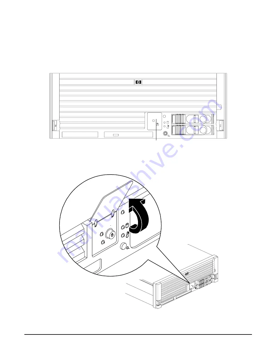
Figure 1-7
Accessing the Control Panel
Control Panel


