background image

 6 

Safety and Regulatory Information for HP PS1810-8G Switch

To avoid personal injury or product damage when installing your switch, read the installation precautions and guidelines below. 

For additional Safety and Regulatory information, refer to the Safety and Regulatory documentation included with your
switch, to the safety and regulatory documentation on the HP web site at 

www.hp.com/support/Safety-Compliance-

EnterpriseProducts

, and to the switch

 Installation and Getting Started Guide

 that can be found on the HP Networking web 

site: 

www.hp.com/networking/support

.

Installation Precautions

Warnings

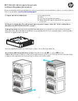
Do not wall-mount any switch without checking for restrictions in the 

Installation and Getting Started 

Guide

Wall-mount the switch with network ports facing up or down (away from or toward the floor).

If mounting the switch under HP ProLiant MicroServer Gen8s, stack no more than two servers on top of 
the switch.

Cautions

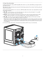
Ensure the power source circuits are properly grounded, then use the in-line power adapter and power cord, or wall 
mount power adapter supplied with the switch to connect to the AC power source.

If your installation requires a different power cord than the one supplied with the power adapter, be sure the cord 
is adequately sized for the switch’s current requirements. In addition, be sure to use a power cord displaying the 
mark of the safety agency that defines the regulations for power cords in your country/region. The mark is your 
assurance that the power cord can be used safely with the switch and power adapter.

When installing the switch, the AC outlet should be near the switch and should be easily accessible in case the switch 
must be powered off.

Ensure the switch does not overload the power circuits, wiring, and over-current protection. To determine the 
possibility of overloading the supply circuits, add together the ampere ratings of all devices installed on the same 
circuit as the switch and compare the total with the rating limit for the circuit. The maximum ampere ratings are 
usually printed on the devices near the AC power connectors, and are included under “Product Specifications” on 
page 7.

Do not install the switch in an environment where the operating ambient temperature exceeds its specification.

Ensure the air flow around the switch is not restricted. Leave at least 3 inches (7.6 cm) for cooling.

Summary of Contents for PS1810-8G

Page 1: ...latory Information for HP PS1810 8G Switch on page 6 3 Mount the switch Stack the switch with HP ProLiant MicroServers or mount it on a wall or on top of or under a horizontal surface Before stacking it with HP servers or positioning the switch on a horizontal surface attach the rubber feet that are supplied in the accessory kit If you are mounting the switch on a wall or under a surface do not at...

Page 2: ...n place Important For wall mounting the network ports must be facing up or down See Installation Precautions on page 6 Under Surface Mounting Install the two screws on the surface bottom similarly to the procedures for wall mounting Then position the switch over the screws and slide to lock in place Install the third screw at the side of the switch to prevent it from sliding out of the locked posi...

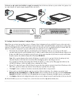
Page 3: ...ation between the switch and the server connect a network cable between any of the available switch ports and either one of the server s Ethernet ports Connection to Ethernet port 2 is shown to to be able to discover and monitor the health status of HP servers from the switch connect a network cable between any of the available switch ports and the server s iLO port Note It is also possible to use...

Page 4: ...ess 192 168 2 10 Note If you cannot determine the switch s IP address you can force it to use the 192 168 2 10 address by first disconnecting the switch from the network and then unplugging and reconnecting power to it To communicate with the switch using the 192 168 2 10 address go to the section Managing the Switch via the 192 168 2 10 Address on the next page before continuing these steps b Fro...

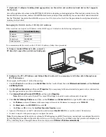
Page 5: ...art button and then click Control Panel In the Control Panel then click Network and Internet and then Network and Sharing Center 2 Click LocalAreaConnection and then click Properties If you are prompted for an administrator password or confirmation type the password or provide confirmation 3 Click Internet Protocol Version 4 TCP IPv4 and then click Properties Note Be sure to record all your PC s c...

Page 6: ...itch to connect to the AC power source If your installation requires a different power cord than the one supplied with the power adapter be sure the cord is adequately sized for the switch s current requirements In addition be sure to use a power cord displaying the mark of the safety agency that defines the regulations for power cords in your country region The mark is your assurance that the pow...

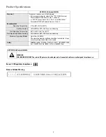
Page 7: ... to 95 at 40 C 104 F non condensing Non Operating Temperature 40 C to 70 C 40 F to 158 F Non Operating Relative humidity 15 to 90 at 65 C 149 F non condensing Maximum Operating Altitude Up to 3 km 10 000 ft The operating maximum altitude should not exceed that of any accessory being connected to the switch Safety EN60950 1 2006 A11 2009 A1 2010 A12 2011 IEC60950 1 2005 Am 1 2009 CSA22 2 No 60950 1...

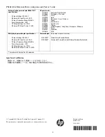
Page 8: ...dia Indonesia Israel Vietnam Japan South Africa South Korea Taiwan United Kingdom Hong Kong Singapore Malaysia Brazil Argentina Chile Wall plug in power adapter specifications AC Input Voltage 100 240 V Maximum AC Input Current 0 4 A AC Input Frequency Range 50 60 Hz Power Consumption 13 W DC Output Voltage 12 10 V Maximum DC Output Current 1 085 A Poweradapter 5184 5863 5184 5864 AC power cords a...

Reviews: