background image


Hardware options installation  18 

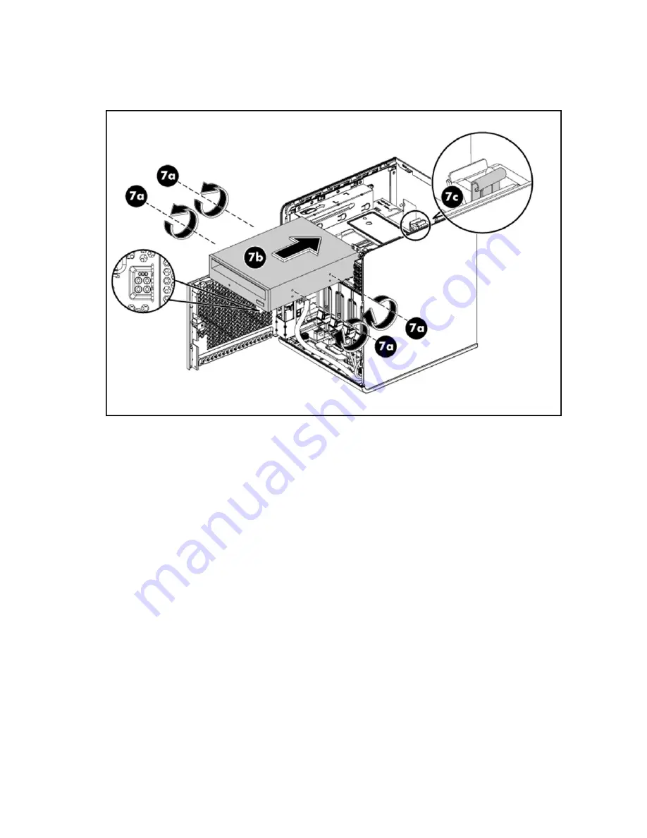
a.


Remove four spare drive screws from the rear side of the panel door. 

b.


Install the screws onto the drive. 

c.


Slide the drive into the media drive bay until it clicks into place. 


8.


Connect the optical drive cables: 

a.


Connect the data cable to the optical drive, and then connect the end to the system board (J24). 

Summary of Contents for ProLiant MicroServer

Page 1: ... person who installs administers and troubleshoots servers and storage systems HP assumes you are qualified in the servicing of computer equipment and trained in recognizing hazards in products with hazardous energy levels Part Number 615717 006 December 2012 Edition 6 ...

Page 2: ...et forth in the express warranty statements accompanying such products and services Nothing herein should be construed as constituting an additional warranty HP shall not be liable for technical or editorial errors or omissions contained herein Microsoft Windows and Windows Server are U S registered trademarks of Microsoft Corporation AMD is a trademark of Advanced Micro Devices Inc ...

Page 3: ...13 Resetting the MicroServer Remote Access Card password to default 13 SATA drive options 14 Optical disc drive 16 RDX drive option 20 Memory options 24 Memory subsystem architecture 24 Single rank and dual rank DIMMs 25 UDIMM maximum memory configurations 25 Installing DIMMs 25 HP Trusted Platform Module option 27 Installing the Trusted Platform Module board 28 Retaining the recovery key password...

Page 4: ...tart diagnosis flowchart 43 General diagnosis flowchart 44 Power on problems flowchart 46 POST problems flowchart 47 OS boot problems flowchart 49 Server fault indications flowchart 50 Hardware problems 51 Power problems 52 General hardware problems 53 Internal system problems 56 System open circuits and short circuits 62 External device problems 62 Mouse and keyboard problems 63 Network controlle...

Page 5: ...e households in the European Union 76 Japanese notice 77 BSMI notice 77 Korean notice 77 Chinese notice 78 Laser compliance 78 Battery replacement notice 78 Taiwan battery recycling notice 79 Power cord statement for Japan 79 Acoustics statement for Germany Geräuschemission 79 Electrostatic discharge 80 Preventing electrostatic discharge 80 Grounding methods to prevent electrostatic discharge 80 S...

Page 6: ...he operating system documentation 3 Press the Power On Standby button to place the server in standby mode When the server activates standby power mode the system power LED changes to amber 4 Disconnect the power cords The system is now without power Open the panel door WARNING To reduce the risk of personal injury from hot surfaces allow the drives and the internal system components to cool before...

Page 7: ...Operations 7 4 Open the panel door of the server For server specific information see the installation sheet that ships with the server ...

Page 8: ...nt When installing the server select a location that meets the environmental standards described in this section Temperature requirements To ensure continued safe and reliable equipment operation install or position the system in a well ventilated climate controlled environment The maximum recommended ambient operating temperature TMRA for most server products is 35 C 95 F The temperature in the r...

Page 9: ...must install the equipment in accordance with NFPA 70 1999 Edition National Electric Code Article 250 as well as any local and regional building codes In Canada you must install the equipment in accordance with Canadian Standards Association CSA C22 1 Canadian Electrical Code In all other countries you must install the equipment in accordance with any regional or national electrical wiring codes s...

Page 10: ...an operating system on the server insert the operating system DVD into the DVD ROM drive optional and then reboot the server The updates are available on the HP website http www hp com support To begin the installation process follow the on screen instructions Registering the server To register the server see the HP Registration website http register hp com ...

Page 11: ...rge Preventing electrostatic discharge To prevent damaging the system be aware of the precautions you need to follow when setting up the system or handling parts A discharge of static electricity from a finger or other conductor may damage system boards or other static sensitive devices This type of damage may reduce the life expectancy of the device To prevent electrostatic damage Avoid hand cont...

Page 12: ...lowing references and software tools might also be used IPMI Event Log Diagnostics software Server warnings and cautions WARNING To reduce the risk of personal injury from hot surfaces allow drives and internal system components to cool before touching them CAUTION The server must always be operated with the system covers on Proper cooling is not achieved when the system covers are removed CAUTION...

Page 13: ...nce After completing any removal or replacement procedure run the diagnostics program to verify that all components operate properly HP MicroServer Remote Access Card The operating system has the BMC Setup function when the IPMI card is installed into the server By BIOS default the server exports the VGA port through the VGA connector on the IPMI card automatically when the IPMI card is plugged Yo...

Page 14: ...n about product features specifications options configurations and compatibility see the product QuickSpecs on the HP Product Bulletin website http www hp com go productbulletin The HP ProLiant MicroServer supports up to four non hot plug hard drives To install the component 1 Power down the server on page 6 2 Place the server on a flat level work surface 3 Open the panel door on page 6 4 Remove t...

Page 15: ...e screws from the rear side of the panel door 6 Install the drive in the drive carrier a Align the drive inside the carrier b Use the screws to secure the drive in the carrier 7 Install the drive in the drive bay a Slide the drive assembly into the drive bay ...

Page 16: ...ckSpecs on the HP Product Bulletin website http www hp com go productbulletin The removable media drive bay supports an optical drive a tape drive or an RDX drive The section describes how to install an optical drive For information on how to install an RDX drive see RDX drive option on page 20 To install the component 1 Power down the server on page 6 2 Place the server on a flat level work surfa...

Page 17: ...op panel forward and then lift it to release it from the chassis 6 Use a screwdriver to toggle the metal faceplate off the top panel The metal faceplate is no longer needed when the removable media drive bay is occupied 7 Install the optical drive ...

Page 18: ...om the rear side of the panel door b Install the screws onto the drive c Slide the drive into the media drive bay until it clicks into place 8 Connect the optical drive cables a Connect the data cable to the optical drive and then connect the end to the system board J24 ...

Page 19: ...ower cable to the optical drive and then connect the other end to the power supply unit optical drive power connector P6 9 Slide the top panel back onto the chassis 10 Tighten the rear thumbscrew to lock the top panel in place 11 Close the panel door ...

Page 20: ...pecifications options configurations and compatibility see the product QuickSpecs on the HP Product Bulletin website http www hp com go productbulletin To install the component 1 Power down the server on page 6 2 Place the server on a flat level work surface 3 Open the panel door on page 6 4 Loosen the rear thumbscrew that locks the top panel on the chassis ...

Page 21: ... top panel forward and then lift it to release it from the chassis 6 Use a screwdriver to toggle the metal faceplate off the top panel The metal faceplate is no longer needed when the removable media drive bay is occupied 7 Connect the RDX cables ...

Page 22: ... bay b Connect the data cable to the USB connector on the system board and then route the cable up and through the cable tunnel on the left side of the media drive bay 8 Install the RDX drive a Remove four spare drive screws from the rear side of the panel door b Install the screws onto the drive c Connect the data and power cables to the drive ...

Page 23: ... the drive into the media drive bay until it clicks into place 9 Install the RDX disk cartridge into the drive 10 Slide the top panel back onto the chassis 11 Tighten the rear thumbscrew to lock the top panel in place 12 Close the panel door ...

Page 24: ...ory capacity of 8 GB Memory subsystem architecture The memory subsystem in this server is divided into channels Each processor supports two channels and each channel supports two DIMM slots as shown in the following table Channel Slot Slot number 1 A 1 2 B 2 This multi channel architecture provides enhanced performance in Advanced ECC mode This architecture also enables the Mirrored Memory and Loc...

Page 25: ...y For example if current DRAM technology supports 2 GB single rank DIMMs a dual rank DIMM would be 4 GB UDIMM maximum memory configurations The server supports a maximum of 8 GB using 4 GB dual rank UDIMMs Installing DIMMs CAUTION To avoid damage to the hard drives memory and other system components the air baffle drive blanks and access panel must be installed when the server is powered up For mo...

Page 26: ...em board 5 Open the DIMM slot latches CAUTION The DIMM slots are structured to ensure proper installation If you try to insert a DIMM but it does not fit easily into the slot you may have positioned it incorrectly Reverse the orientation of the DIMM and insert it again 6 Install the memory module a Completely open the holding clips securing the module b Align the notch on the bottom edge of the me...

Page 27: ...lling the Trusted Platform Module board on page 28 2 Retaining the recovery key password on page 29 3 Enabling the Trusted Platform Module on page 30 Enabling the TPM requires accessing RBSU ROM Based Setup Utility on page 31 For more information about RBSU see the HP website http www hp com go ilomgmtengine docs TPM installation requires the use of drive encryption technology such as the Microsof...

Page 28: ...able for blocked data access caused by improper TPM use For operating instructions see the encryption technology feature documentation provided by the operating system Installing the Trusted Platform Module board WARNING To reduce the risk of personal injury electric shock or damage to the equipment remove the power cord to remove power from the server The front panel Power On Standby button does ...

Page 29: ...nerated during BitLocker setup and can be saved and printed after BitLocker is enabled When using BitLocker always retain the recovery key password The recovery key password is required to enter Recovery Mode after BitLocker detects a possible compromise of system integrity To help ensure maximum security observe the following guidelines when retaining the recovery key password Always store the re...

Page 30: ...lled and enabled on the server data access is locked if you fail to follow the proper procedures for updating the system or option firmware replacing the system board replacing a hard drive or modifying OS application TPM settings For more information on firmware updates and hardware procedures see the HP Trusted Platform Module Best Practices White Paper on the HP website http www hp com support ...

Page 31: ...he number of drives connected to the server NOTE The server may not support all the following examples NOTE If the boot drive is not empty or has been written to in the past ORCA does not automatically configure the array You must run ORCA to configure the array settings Drive configuration RAID function smart array controller RAID function software 2 0 or 1 0 or 1 To change any ORCA default setti...

Page 32: ...rver management functions Using HP MicroServer remote access card you can do the following Remotely power up power down or reboot the host server Send alerts from HP MicroServer remote access card regardless of the state of the host server USB support HP provides both standard USB 2 0 support and legacy USB 2 0 support Standard support is provided by the OS through the appropriate USB device drive...

Page 33: ...g the SATA RAID feature in RBSU on page 33 2 Create a RAID volume Enabling the SATA RAID feature in RBSU CAUTION Back up any data stored on the hard drives before proceeding The configuration process erases all data on the hard drives 1 Power up the server If the server is already powered save all data exit all open applications and restart NOTE Enabling the RAID option in RBSU is only necessary f...

Page 34: ...h a USB diskette drive HP MicroServer remote access card Virtual Floppy or Virtual Floppy with the embedded SATA RAID Windows driver Some servers do not ship with these drives as standard hardware Diskette and CD ROM drive options To acquire a diskette drive option or CD ROM drive option for a server contact an HP authorized reseller For the name of the nearest HP authorized reseller In the United...

Page 35: ...ty press Ctrl F 5 Create an array and then exit the RAID Option ROM Utility The POST process continues 6 Install the operating system Installing the operating system on page 10 For information about installing an operating system see the documentation that shipped with the server Installing the Embedded SATA RAID driver by using Virtual Floppy 1 Ensure that a network cable is connected to the HP M...

Page 36: ...ext action 4 Press the S key to specify the driver from the diskette Then press the Enter key The OS searches the diskette for a suitable driver 5 After locating the AMD Embedded SATA RAID driver press Enter 6 Follow the remaining on screen instructions to complete the installation Installing a supported Linux OS To install a supported Linux OS see the OS documentation IMPORTANT This server suppor...

Page 37: ...leshooting the server Important safety information Before servicing this product read the Important Safety Information document provided with the server Symbols on equipment The following symbols may be placed on equipment to indicate the presence of potentially hazardous conditions This symbol indicates the presence of hazardous energy circuits or electric shock hazards Refer all servicing to qua...

Page 38: ... of the complexity of the individual boards and subassemblies no one should attempt to make repairs at the component level or to make modifications to any printed wiring board Improper repairs can create a safety hazard WARNING To reduce the risk of personal injury or damage to the equipment be sure that The leveling feet are extended to the floor The full weight of the rack rests on the leveling ...

Page 39: ...unded earthed To ensure proper operation plug the AC power cord into a properly grounded AC outlet only Symptom information Before troubleshooting a server problem collect the following information What events preceded the failure After which steps does the problem occur What has been changed since the time the server was working Did you recently add or remove hardware or software If so did you re...

Page 40: ...s o CPU initial failed o Memory initial failed o Fan failure or missing o Memory uncorrectable ECC Non critical issues o Voltage fault o Temperature fault Preparing the server for diagnosis 1 Be sure the server is in the proper operating environment with adequate power air conditioning and humidity control Refer to the server documentation for required environmental conditions 2 Record any error m...

Page 41: ...eck all data and power cables for damage Be sure no cables have bent pins or damaged connectors If a fixed cable tray is available for the server be sure the cords and cables connected to the server are routed correctly through the tray Be sure each device is properly seated Avoid bending or flexing circuit boards when reseating components If a device has latches be sure they are completely closed...

Page 42: ...und a DIMM Avoid touching the components on the sides of the DIMM Never bend or flex the DIMM When installing a DIMM observe the following guidelines Before seating the DIMM align the DIMM with the slot To align and seat the DIMM use two fingers to hold the DIMM along the side edges To seat the DIMM use two fingers to apply gentle pressure along the top of the DIMM For more information see the HP ...

Page 43: ... used when the problem is not server specific or is not easily categorized into the other flowcharts The available flowcharts include Start diagnosis flowchart on page 43 General diagnosis flowchart on page 44 Server power on problems flowchart Power on problems flowchart on page 46 POST problems flowchart on page 47 OS boot problems flowchart on page 49 Server fault indications flowchart on page ...

Page 44: ... 2 Loose connections on page 41 3 Service notifications on page 41 4 The most recent version of a particular server or option firmware is available on the HP website http www hp com support 5 General memory problems are occurring on page 60 6 Server maintenance and service guide located on the HP website http www hp com products servers platforms Hardware problems on page 51 Server maintenance and...

Page 45: ...intenance and service guide located on the HP website http www hp com products servers platforms Hardware problems on page 51 8 Server information you need Operating system information you need on page 70 9 HP contact information on page 81 ...

Page 46: ...problem Power on circuit problem Improperly seated component or interlock problem Faulty internal component Item See 1 Server maintenance and service guide located on the HP website http www hp com products servers platforms 2 General diagnosis flowchart on page 44 3 Loose connections on page 41 4 Power source problems on page 52 5 Power supply problems on page 52 Server maintenance and service gu...

Page 47: ... Server does not complete POST NOTE The server has completed POST when the system attempts to access the boot device Server completes POST with errors Possible problems Improperly seated or faulty internal component Faulty KVM device Faulty video device ...

Page 48: ...tions on page 41 3 General memory problems are occurring on page 60 4 Hardware problems on page 51 Server maintenance and service guide located on the HP website http www hp com products servers platforms 5 Symptom information on page 39 6 Server information you need Operating system information you need on page 70 7 HP contact information on page 81 ...

Page 49: ... Item See 1 HP Insight Diagnostics ProLiant MicroServer Insight Diagnostics on page 32 2 Operating system problems on page 65 HP contact information on page 81 3 General memory problems are occurring on page 60 4 Hardware problems on page 51 Server maintenance and service guide located on the HP website http www hp com products servers platforms 5 General diagnosis flowchart on page 44 ...

Page 50: ...ternal health LED or external health LED is red or amber NOTE For the location of server LEDs and information on their statuses refer to the server documentation Possible causes Improperly seated or faulty internal or external component Unsupported component installed Redundancy failure ...

Page 51: ...servers platforms 2 Power on problems flowchart on page 46 3 HP Insight Diagnostics ProLiant MicroServer Insight Diagnostics on page 32 4 Hardware problems on page 51 Server maintenance and service guide located on the HP website http www hp com products servers platforms 5 HP contact information on page 81 Hardware problems Power problems on page 52 ...

Page 52: ...ure the proper circuit breaker is in the On position 7 If Enclosure Dynamic Power Capping or Enclosure Power Limit is enabled on supported servers be sure there is sufficient power allocation to support the server For more information see the following documents o The HP Power Capping and HP Dynamic Power Capping for ProLiant servers technology brief on the HP website http h20000 www2 hp com bc do...

Page 53: ...ode can be turned off through the configuration mode on the front panel 9 Change the battery to be sure damage was not caused by excessive heat particularly if a recent air conditioning outage has occurred NOTE The optimal operating temperature for UPS batteries is 25 C 77 F For approximately every 8 C to 10 C 16 F to 18 F average increase in ambient temperature above the optimal temperature batte...

Page 54: ...e using a Smart Array controller you need the latest Smart Array Controller device driver 9 Be sure all device drivers are the correct ones for the hardware Uninstall any incorrect drivers before installing the correct drivers 10 Press the F10 key to run the BIOS Setup Utility after boards or other options are installed or replaced to be sure all system components recognize the changes If you do n...

Page 55: ...le a third party PCI or PCI X board may be required to be installed on the primary PCI or PCI X bus respectively Testing the device Action 1 Uninstall the device If the server works with the device removed and uninstalled a problem exists with the device the server does not support the device or a conflict exists with another device 2 If the device is the only device on a bus be sure the bus works...

Page 56: ... been applied to the surface of the CD or DVD in use remove the label and any adhesive residue 3 Be sure the inserted CD or DVD format is valid for the drive For example be sure you are not inserting a DVD into a drive that only supports CDs Drive is not detected Action 1 Be sure no loose connections on page 41 exist 2 Refer to the drive documentation to be sure cables are connected as required 3 ...

Page 57: ...ors are occurring Action Replace the drive Diskette drive problems Diskette drive light stays on Action 1 Be sure no loose connections on page 41 exist 2 Be sure the diskette is not damaged Run the diskette utility on the diskette CHKDSK on some systems 3 Be sure the diskette is properly inserted Remove the diskette and reinsert correctly into the drive 4 Be sure the diskette drive is cabled prope...

Page 58: ...you have been operating the server for an extended period of time with the access panel removed airflow may have been impeded causing thermal damage to components Refer to the server documentation for further requirements 4 Be sure no POST error messages are displayed while booting the server that indicate temperature violation or fan failure information Refer to the server documentation for the t...

Page 59: ...ure a conflict does not exist with another hard drive Check for SCSI ID conflicts 7 Be sure the correct drive controller drivers are installed A new hard drive is not recognized Action 1 Be sure the drive is supported To determine drive support see the server documentation or the HP website http www hp com go bizsupport 2 Be sure the drive bay is not defective by installing the hard drive in anoth...

Page 60: ... working DIMM o Remove any third party memory To test the memory run ProLiant MicroServer Insight Diagnostics on page 32 Server is out of memory Action 1 Be sure the memory is configured properly Refer to the application documentation to determine the memory configuration requirements 2 Be sure no operating system errors are indicated 3 Be sure a memory count error Memory count error exists on pag...

Page 61: ... in improper airflow and improper cooling that can lead to thermal damage 1 If applicable check the PPM LEDs to identify if a PPM failure occurred For information on LEDs refer to the server documentation 2 Reseat each PPM and then restart the server 3 If reseating the PPMs is not effective remove all but one PPM restart the server to see if the PPM is working and then install each PPM individuall...

Page 62: ...r in this manner results in improper airflow and improper cooling that can lead to thermal damage 1 Check the server LEDs to see if any statuses indicate the source of the problem For LED information refer to the server documentation 2 Remove all power sources to the server 3 Be sure no loose connections on page 41 exist in the area 4 Be sure each component in the area is working Refer to the sect...

Page 63: ...bled if a key symbol is displayed on the screen when POST completes If you do not have access to the password you must disable the power on password by using the Password Disable switch on the system board Refer to the server documentation 9 If the video expansion board is installed in a PCI Hot Plug slot be sure the slot has power by checking the power LED on the slot if applicable Refer to the s...

Page 64: ...ee if any statuses indicate the source of the problem For LED information refer to the network controller documentation 2 Be sure no loose connections on page 41 exist 3 Be sure the network cable is working by replacing it with a known functional cable 4 Be sure a software problem has not caused failure Refer to the operating system documentation for guidelines on adding or replacing PCI Hot Plug ...

Page 65: ...stall the network driver 4 Refer to the operating system documentation to be sure the correct drivers are installed 5 Refer to the operating system documentation to be sure that the driver parameters match the configuration of the network controller Problems are occurring with the network interconnect blades Action Be sure the network interconnect blades are properly seated and connected Software ...

Page 66: ... updating the operating system Operating system updates on page 66 Operating system updates Use care when applying operating system updates Service Packs hotfixes and patches Before updating the operating system read the release notes for each update If you do not require specific fixes from the update it is recommended that you do not apply the updates Some updates overwrite files specific to HP ...

Page 67: ...rating system recovery software o Microsoft operating systems Windows Server 2008 Automated System Recovery Diskette If the operating system was factory installed click Start All Programs Accessories System Tools to access the backup utility Refer to the operating system documentation for more information o Linux Refer to the operating system documentation for information Linux operating systems F...

Page 68: ...ologies to help ensure that HP servers provide maximum uptime with minimal maintenance Many of these technologies also reduce server management efforts enabling administrators to work on issues and resolve problems without taking servers offline The process of updating system or option firmware is referred to as a flash process or flashing the ROM A firmware or ROM flash removes the existing versi...

Page 69: ... target server and then reboot using the correct ROMPaq diskette or USB drive key for that server 3 Follow the interactive session in the ROMPaq utility and then select the devices to be flashed 4 After the ROMPaq utility flashes the ROM for the selected devices cycle power manually to reboot the system back into the operating system Option ROMPaqs have been retired as an upgrade delivery method f...

Page 70: ...on the problem you may be asked for certain pieces of information Be prepared to access the information listed in the following sections based on operating system used Microsoft operating systems Collect the following information Whether the operating system was factory installed Operating system version number A current copy of the following files o Boot ini o Memory dmp o Event logs o Dr Watson ...

Page 71: ...uname a o cat proc meminfo o cat proc cpuinfo o rpm ga o dmesg o lsmod o ps ef o ifconfig a o chkconfig list o mount Contents of the following files o var log messages o etc modules conf or etc conf modules o etc lilo conf or etc grub conf o etc fstab If HP drivers are installed o Version of the drivers used o List of drivers A list of each third party hardware component installed with the firmwar...

Page 72: ...the battery Do not expose the battery to temperatures higher than 60 C 140 F Do not disassemble crush puncture short external contacts or dispose of in fire or water Replace only with the spare designated for this product To remove the component 1 Power down the server on page 6 2 Remove the access panel and then pull out the motherboard tray CAUTION To prevent damage to the server or expansion bo...

Page 73: ...tery replacement 73 To replace the component reverse the removal procedure For more information about battery replacement or proper disposal contact an authorized reseller or an authorized service provider ...

Page 74: ... to bear a label indicating the interference potential of the device as well as additional operating instructions for the user FCC rating label The FCC rating label on the device shows the classification A or B of the equipment Class B devices have an FCC logo or ID on the label Class A devices do not have an FCC logo or ID on the label After you determine the class of the device refer to the corr...

Page 75: ...cause harmful interference and 2 this device must accept any interference received including interference that may cause undesired operation For questions regarding this product contact us by mail or telephone Hewlett Packard Company P O Box 692000 Mail Stop 530113 Houston Texas 77269 2000 1 800 HP INVENT 1 800 474 6836 For continuous quality improvement calls may be recorded or monitored For ques...

Page 76: ...thin the product documentation or at the following HP website http www hp eu certificates type the product number in the search field Compliance is indicated by the CE marking as shown below Where applicable for telecommunications products a 4 digit notified body number may follow it as a suffix Please refer to the regulatory label provided on the product The point of contact for regulatory matter...

Page 77: ...Regulatory compliance notices 77 Japanese notice BSMI notice Korean notice Class A equipment Class B equipment ...

Page 78: ...erein Allow only HP Authorized Service technicians to repair the unit The Center for Devices and Radiological Health CDRH of the U S Food and Drug Administration implemented regulations for laser products on August 2 1976 These regulations apply to laser products manufactured from August 1 1976 Compliance is mandatory for products marketed in the United States Battery replacement notice WARNING Th...

Page 79: ... Disposal Act to indicate the recovery marks on the batteries used in sales giveaway or promotion Contact a qualified Taiwanese recycler for proper battery disposal Power cord statement for Japan Acoustics statement for Germany Geräuschemission Schalldruckpegel LpA 70 dB A Zuschauerpositionen bystander positions Normaler Betrieb normal operation Nach ISO 7779 1999 Typprüfung ...

Page 80: ...tic sensitive component or assembly Grounding methods to prevent electrostatic discharge Several methods are used for grounding Use one or more of the following methods when handling or installing electrostatic sensitive parts Use a wrist strap connected by a ground cord to a grounded workstation or computer chassis Wrist straps are flexible straps with a minimum of 1 megohm 10 percent resistance ...

Page 81: ...igned for customer self repair If however you require that HP replace them for you there may or may not be additional charges depending on the type of warranty service designated for your product NOTE Some HP parts are not designed for customer self repair In order to satisfy the customer warranty HP requires that an authorized service provider replace the part These parts are identified as No in ...

Page 82: ...néralement cinq 5 jours ouvrés La pièce et sa documentation doivent être retournées dans l emballage fourni Si vous ne retournez pas la pièce défectueuse HP se réserve le droit de vous facturer les coûts de remplacement Dans le cas d une pièce CSR HP supporte l ensemble des frais d expédition et de retour et détermine la société de courses ou le transporteur à utiliser Pour plus d informations sur...

Page 83: ...P vornehmen lassen möchten können bei diesem Service je nach den für Ihr Produkt vorgesehenen Garantiebedingungen zusätzliche Kosten anfallen HINWEIS Einige Teile sind nicht für Customer Self Repair ausgelegt Um den Garantieanspruch des Kunden zu erfüllen muss das Teil von einem HP Servicepartner ersetzt werden Im illustrierten Teilekatalog sind diese Teile mit No bzw Nein gekennzeichnet CSR Teile...

Page 84: ...do normalmente cinco días laborables Los componentes defectuosos deberán devolverse con toda la documentación relacionada y con el embalaje de envío Si no enviara el componente defectuoso requerido HP podrá cobrarle por el de sustitución En el caso de todas sustituciones que lleve a cabo el cliente HP se hará cargo de todos los gastos de envío y devolución de componentes y escogerá la empresa de t...

Page 85: ...e ao cliente Existem duas categorias de peças CSR Obrigatória Peças cujo reparo feito pelo cliente é obrigatório Se desejar que a HP substitua essas peças serão cobradas as despesas de transporte e mão de obra do serviço Opcional Peças cujo reparo feito pelo cliente é opcional Essas peças também são projetadas para o reparo feito pelo cliente No entanto se desejar que a HP as substitua pode haver ...

Page 86: ...Support and other resources 86 ...

Page 87: ...Support and other resources 87 ...

Page 88: ...uide on the HP website http www hp com go ilo docs Onboard Administrator SHOW ALL report for HP BladeSystem products only For more information on obtaining the Onboard Administrator SHOW ALL report see the HP website http h20000 www2 hp com bizsupport TechSupport Document jsp lang en cc us objectID c 02843807 Technical support registration number if applicable Product serial number Product model n...

Page 89: ...ontroller CS cable select DAT digital audio tape IDE integrated device electronics IEC International Electrotechnical Commission IPMI Intelligent Platform Management Interface IRQ interrupt request KVM keyboard video and mouse NVRAM nonvolatile memory ODD Optical Disk Drive ORCA Option ROM Configuration for Arrays ...

Page 90: ...onnect extended PDU power distribution unit POST Power On Self Test PPM processor power module RBSU ROM Based Setup Utility SATA serial ATA TMRA recommended ambient operating temperature TPM Trusted Platform Module UDIMM unregistered dual in line memory module UPS uninterruptible power system USB universal serial bus ...

Page 91: ...oviding documentation that meets your needs To help us improve the documentation send any errors suggestions or comments to Documentation Feedback mailto docsfeedback hp com Include the document title and part number version number or the URL when submitting your feedback ...

Page 92: ... DAT drives 56 57 data loss 56 data recovery 56 59 Declaration of Conformity 75 DIMMs 25 42 diskette drive 34 57 diskette drive problems 57 58 drive errors 57 58 drive failure detecting 56 drive not found 57 59 drive problems 56 57 drives 42 58 drives installing 11 DVD ROM drive 56 E electrical grounding requirements 9 electrostatic discharge 11 80 Embedded SATA RAID 33 embedded SATA RAID installi...

Page 93: ...anagement tools 32 memory 60 memory count error 60 memory not recognized 60 memory overview 24 memory problems 60 memory subsystem architecture 24 Microsoft operating systems 36 70 modifications FCC notice 75 monitor 63 mouse 63 mouse problems 63 N network controller problems 64 network controllers 64 65 network interconnect blades 65 O operating system crash 65 operating system problems 65 operat...

Page 94: ...tifications 41 Service Packs 66 short circuits 62 site requirements 8 software errors 67 68 software failure 67 software problems 65 software troubleshooting 67 68 start diagnosis flowchart 43 static electricity 11 Subscriber s Choice 33 support 81 symbols on equipment 37 symptom information 39 system board battery 72 78 system ROM 68 system keeping current 32 T Taiwan battery recycling notice 79 ...

Reviews: