HP ProLiant DL170h G6 Installation Sheet Download Page 7


CAUTION:

  To prevent the heat sink from tilting to one side 

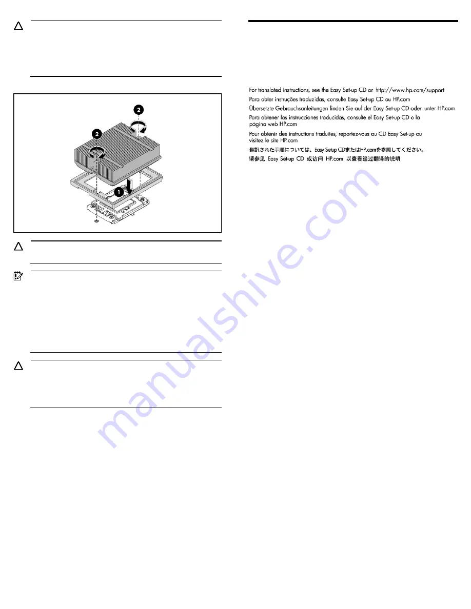
during installation/removal, turn each screw a couple of turns, 

alternatively between both of them, and then apply the final 

torque. Do not over tighten the spring loaded screws to prevent 

them from breaking off. A maximum torque of 4.5 inch-lb is set 

for each screw. 

Figure 14 

Installing the heat sink assembly 


CAUTION:

  Be sure that the heat sink sits squarely on the processor, 

or overheating and damage to the processor may occur. 


IMPORTANT:

 If the heat sink has been removed for any reason, 

it is critical that you apply more thermal interface material to the 

integrated heat spreader on the processor to ensure proper 

thermal bonding between the processor and the heat sink. 

Clean the contact surface of both the processor and heat sink 

with an alcohol pad, then re-apply an HP-approved thermal 

interface material before reinstalling the processor. Use a 

pattern of five dots when applying the thermal interface 

material—one dot in the center, and one dot at each corner. 


CAUTION:

  To prevent the heat sink from tilting to one side 

during installation removal procedures, use a diagonally 

opposite pattern (an “X” pattern) when tightening the four 

spring-loaded screws. Do not over tighten the heat sink’s 

spring-loaded screws to prevent them from breaking off. 


Additional Documentation 

For additional documentation, refer to HP ProLiant DL170h G6 Easy 

Set-up CD. You can also access additional information and 

documentation from the HP external website, either by connecting 

directly or through the Easy Set-up CD. 


Summary of Contents for ProLiant DL170h G6

Page 1: ...HP ProLiant DL170h G6 Server Installation Sheet Part Number 531486 004 ...

Page 2: ...ew the right node is node 2 and the left node is node 4 Figure 2 Front panel components of a four Node system 16 SFF HDD cage with two optional front power LED kit Item Description 1 Power button of Node 1 2 Chassis UID LED Button 3 Power button of Node 2 4 Health LED of Node 1 5 Health LED of Node 2 6 Power button of Node 3 7 Power button of Node 4 8 Health LED of Node 3 9 Health LED of Node 4 10...

Page 3: ..._ 7 USB 2 0 ports 8 Power button of Node 4 9 Health LED button of Node 4 10 Serial port 11 VGA port 12 Power supply cable socket 1 13 Power supply cable socket 2 IMPORTANT From the rear side view the node in the top right is node 3 bottom right is node 4 top left is node 1 and bottom left is node 2 Server configuration resources In addition to this Installation Sheet other resources are available ...

Page 4: ... it on a flat surface 4 Remove the top cover by following the procedure described later in the Opening the Chassis section Post installation procedures 1 Be sure all components are installed according to the described step by step instructions 2 Check to make sure you have not left loose tools or parts inside the server 3 Reinstall the PCI cage air baffle peripherals and system cables that you hav...

Page 5: ...the module with the keyed surface of the DIMM slot and then press the module fully into the slot Step 1 in Figure 8 2 Firmly press the holding clips inward to secure the memory module in place Step 2 in Figure 8 Figure 8 Installing a memory module DIMM slots are structured to ensure proper installation If you insert a DIMM but it does not fit easily into the slot you may have inserted it incorrect...

Page 6: ...or into the socket 4 Press the tabs on the processor installation tool to separate it from the processor and then remove the tool Figure 12 Removing the tool 5 Close the processor socket retaining bracket and the processor locking lever The processor socket cover is automatically ejected Remove the cover Figure 13 Closing the bracket and lever removing cover CAUTION Be sure to close the processor ...

Page 7: ...mal bonding between the processor and the heat sink Clean the contact surface of both the processor and heat sink with an alcohol pad then re apply an HP approved thermal interface material before reinstalling the processor Use a pattern of five dots when applying the thermal interface material one dot in the center and one dot at each corner CAUTION To prevent the heat sink from tilting to one si...

Page 8: ...es are set forth in the express warranty statements accompanying such products and services Nothing herein should be construed as constituting an additional warranty HP shall not be liable for technical or editorial errors or omissions contained herein Microsoft Windows and Windows NT are U S registered trademarks of Microsoft Corporation Part Number 531486 004 January 2011 Fourth Edition ...

Reviews: