background image


Removal and replacement procedures  65  


Memory module population order

Processor memory 

socket 

10 

11 

12 

Rank support per  

memory socket 

SR/DR  SR/DR/

GR 

SR/D

SR/D

SR/DR/

GR 

SR/D

SR/D

SR/DR/G

SR/D

SR/D

SR/DR/

GR 

SR/DR 

RDIMM Population 

order without QR 

UDIMM Population 
order without QR 


Population order with 
QR along with SR/DR 

Processor memory 

bank number 

NOTES: 
SR = Single Rank, DR = Dual Rank, QR = Quad Rank. 
Population rules must be followed for both processors. 
Memory modules may be populated one at a time per processor, but populating two at a time per processor provides better performance. 
Memory modules should be populated four at a time per processor for best performance. 
Memory modules within a memory bank must be identical for best performance. 
Quad Rank memory module can only be installed in memory sockets 2, 5, 8, and 11. 
For more information on memory configurations, see the server user guide located on the Documentation CD or the HP Support website 

(http://www.hp.com/support). 
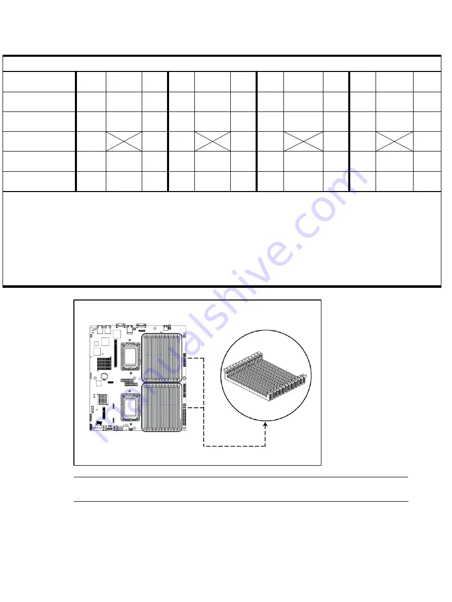
Figure 45


DIMM Slots  


NOTE:

 Before installing the memory, remove the air baffle first. For a detailed procedure, see 

the ”Processor” section in this chapter. 


Summary of Contents for ProLiant DL165 G7

Page 1: ...HP ProLiant DL165 G7 Server Maintenance and Service Guide Part number 601465 001 First edition April 2010 ...

Page 2: ...services are set forth in the express warranty statements accompanying such products and services Nothing herein should be construed as constituting an additional warranty HP shall not be liable for technical or editorial errors or omissions contained herein AMD is trademark or registered trademark of AMD Corporation or its subsidiaries in the United States and other countries ...

Page 3: ... 30 Post installation instructions 30 Server warnings and cautions 31 Symbols on equipment 31 Powering down the server 32 System cover 33 Top cover 33 Drives 34 Cable management 34 Cable connections 35 Drive bay configuration 36 Optical Media Device Bay 39 Hard drives 41 SAS SATA HDD backplane 48 Cable Routing 51 System board configuration 55 Processor 55 Memory 64 PCI expansion card 67 System bat...

Page 4: ...tor 102 Diagnostic tools and setup utilities 103 BIOS software 103 BIOS Setup Utility 103 Accessing the BIOS Setup Utility 103 Navigating through the Setup Utility 104 Setup Utility menu bar 104 BIOS update 110 Power On Self Test POST 110 POST error indicators 111 POST related troubleshooting 111 Physical and operating specifications 112 System unit 112 Index 116 ...

Page 5: ... be shipped for next business day delivery Same day or four hour delivery may be offered at an additional charge where geography permits If assistance is required you can call the HP Technical Support Center and a technician will help you over the telephone HP specifies in the materials shipped with a replacement CSR part whether a defective part must be returned to HP In cases where it is require...

Page 6: ...èces CSR sont livrées le jour ouvré suivant dans la limite des stocks disponibles et selon votre situation géographique Si votre situation géographique le permet et que vous demandez une livraison le jour même ou dans les 4 heures celle ci vous sera facturée Pour bénéficier d une assistance téléphonique appelez le Centre d assistance technique HP Dans les documents envoyés avec la pièce de rechang...

Page 7: ... con consegna entro il giorno lavorativo seguente La consegna nel giorno stesso o entro quattro ore è offerta con un supplemento di costo solo in alcune zone In caso di necessità si può richiedere l assistenza telefonica di un addetto del centro di supporto tecnico HP Nel materiale fornito con una parte di ricambio CSR HP specifica se il cliente deve restituire dei componenti Qualora sia richiesta...

Page 8: ...innerhalb von vier Stunden gegen einen Aufpreis verfügbar Wenn Sie Hilfe benötigen können Sie das HP technische Support Center anrufen und sich von einem Mitarbeiter per Telefon helfen lassen Den Materialien die mit einem CSR Ersatzteil geliefert werden können Sie entnehmen ob das defekte Teil an HP zurückgeschickt werden muss Wenn es erforderlich ist das defekte Teil an HP zurückzuschicken müssen...

Page 9: ...stino al siguiente día laborable Si la situación geográfica lo permite se puede solicitar la entrega en el mismo día o en cuatro horas con un coste adicional Si precisa asistencia técnica puede llamar al Centro de asistencia técnica de HP y recibirá ayuda telefónica por parte de un técnico Con el envío de materiales para la sustitución de componentes CSR HP especificará si los componentes defectuo...

Page 10: ... verzonden voor levering op de eerstvolgende werkdag Levering op dezelfde dag of binnen vier uur kan tegen meerkosten worden aangeboden indien dit mogelijk is gezien de locatie Indien assistentie gewenst is belt u een HP Service Partner om via de telefoon technische ondersteuning te ontvangen HP vermeldt in de documentatie bij het vervangende CSR onderdeel of het defecte onderdeel aan HP moet word...

Page 11: ...rimeiro dia útil após o pedido Onde as condições geográficas permitirem a entrega no mesmo dia ou em quatro horas pode ser feita mediante uma taxa adicional Se precisar de auxílio entre em contato com o Centro de suporte técnico da HP para que um técnico o ajude por telefone A HP especifica nos materiais fornecidos com a peça CSR de reposição se a peça com defeito deve ser devolvida à HP Nos casos...

Page 12: ...Customer self repair 12 ...

Page 13: ...Customer self repair 13 ...

Page 14: ...Customer self repair 14 ...

Page 15: ...Customer self repair 15 ...

Page 16: ...LFF HDD Hot plug Model Item Description Spare Part Number Customer Self Repair 1 PCI cage N A 2 Air baffle 603889 001 Mandatory1 3 Power supply cage 532473 001 Mandatory1 4 Rail kit 573091 001 Mandatory1 5 Hard drive cage 532114 001 Optional2 6 Optical drive blank 532475 001 Mandatory1 7 Hard drive blank 389015 001 Mandatory1 8 Top cover 507262 001 Mandatory1 ...

Page 17: ...atory1 1 Mandatory Parts for which customer self repair is mandatory If you request HP to replace these parts you will be charged for the travel and labor costs of this service 2 Optional Parts for which customer self repair is optional These parts are also designed for customer self repair If however you require that HP replace them for you there may or may not be additional charges depending on ...

Page 18: ...parti siano sostituite da un centro di assistenza autorizzato Tali parti sono identificate da un No nel Catalogo illustrato dei componenti 1 Mandatory Zwingend Teile die im Rahmen des Customer Self Repair Programms ersetzt werden müssen Wenn Sie diese Teile von HP ersetzen lassen werden Ihnen die Versand und Arbeitskosten für diesen Service berechnet 2 Optional Optional Teile für die das Customer ...

Page 19: ...door de klant In verband met de garantievoorwaarden moet het onderdeel door een geautoriseerde Service Partner worden vervangen Deze onderdelen worden in de geïllustreerde onderdelencatalogus aangemerkt met Nee 1 Mandatory Obrigatória Peças cujo reparo feito pelo cliente é obrigatório Se desejar que a HP substitua essas peças serão cobradas as despesas de transporte e mão de obra do serviço 2 Opti...

Page 20: ...Illustrated parts catalog 20 ...

Page 21: ...y 750 W 511778 001 Mandatory1 b Non hot plug power supply 500 W 506247 001 Mandatory1 4 System board 603887 001 Optional2 5 Memory modules DIMM 2GB PC3 10600R 128Mx8 595094 001 Mandatory1 DIMM 4GB PC3 10600R 256Mx4 595095 001 Mandatory1 DIMM 4GB PC3 10600R 512Mx4 595096 001 Mandatory1 DIMM 8GB PC3 10600R 512Mx4 595097 001 Mandatory1 DIMM 16GB PC3 8500R 512Mx4 595098 001 Mandatory1 DIMM 4GB PC3L 85...

Page 22: ...5mm 0 37 in DVD ROM optical drive optional 481430 001 Mandatory1 10 Hard Drives with carriers LFF 160 GB SATA 7 200 rpm 399967 001 Mandatory1 LFF 250 GB SATA 7 200 rpm 399968 001 Mandatory1 LFF 500 GB SATA 7 200 rpm 399969 001 Mandatory1 LFF 750 GB SATA 7 200 rpm 549320 001 Mandatory1 LFF 1 TB SATA 7 200 rpm 545273 001 Mandatory1 LFF 2 TB SATA 7 200 rpm 508040 001 Mandatory1 LFF 36 GB SAS 10 000 r...

Page 23: ... Mandatory1 Control Panel Assembly w cables 603892 001 Optional2 Voltage Regulator Module 536406 001 Optional2 Cable I2C 536399 001 Optional2 Cable USB 538820 001 Optional2 Cable SAS 498425 001 Optional2 Cable BBWBC 488137 001 Optional2 Smart Array Controller Board 462919 001 Optional2 Cache Module 256GB 462974 001 Optional2 Battery Module BBWC 462976 001 Optional2 SD Card Reader Board 608253 001 ...

Page 24: ...es a Hot plug power supply 750 W 511778 001 Mandatory1 b Non hot plug power supply 500 W 506247 001 Mandatory1 4 Voltage Regulator Module 536406 001 Optional2 5 System board 603887 001 Optional2 6 Memory modules DIMM 2GB PC3 10600R 128Mx8 595094 001 Mandatory1 DIMM 4GB PC3 10600R 256Mx4 595095 001 Mandatory1 DIMM 4GB PC3 10600R 512Mx4 595096 001 Mandatory1 DIMM 8GB PC3 10600R 512Mx4 595097 001 Man...

Page 25: ...ptional2 10 9 5mm 0 37 in DVD ROM optical drive 481430 001 Mandatory1 11 Hard Drives with carriers SFF 36 GB SAS 10 000 rpm hot plug 3G 376596 001 Mandatory1 SFF 36 GB SAS 15 000 rpm hot plug dual port 3G 418397 001 Mandatory1 SFF 36 GB SAS 15 000 rpm hot plug 3G 432322 001 Mandatory1 SFF 72 GB SAS 10 000 rpm hot plug 3G 434916 001 Mandatory1 SFF 72 GB SAS 15 000 rpm hot plug dual port 418398 001 ...

Page 26: ...al charges depending on the type of warranty service designated for your product 3 No Some HP parts are not designed for customer self repair In order to satisfy the customer warranty HP requires that an authorized service provider replace the part These parts are identified as No in the Illustrated Parts Catalog 1 Mandatory Obligatoire Pièces pour lesquelles la réparation par le client est obliga...

Page 27: ...ra de dicho servicio 2 Optional Opcional componentes para los que la reparación por parte del usuario es opcional Estos componentes también están diseñados para que puedan ser reparados por el usuario Sin embargo si precisa que HP realice su sustitución puede o no conllevar costes adicionales dependiendo del tipo de servicio de garantía correspondiente al producto 3 No No Algunos componentes no es...

Page 28: ... 800 HP INVENT 1 800 474 6836 This service is available 24 hours a day 7 days a week For continuous quality improvement calls may be recorded or monitored If you have purchased a Care Pack service upgrade call 1 800 633 3600 For more information about Care Packs refer to the HP website at http www hp com Outside North America call the nearest HP Technical Support Phone Center For telephone numbers...

Page 29: ...tools You will need the following tools T 10 T 15 wrench The following references and software tools will assist with the hardware configuration HP ProLiant DL165 G7 Server Easy Set up CD IPMI Event Log Diagnostics Software Hardware configuration information Electrostatic discharge information An electrostatic discharge ESD can damage static sensitive devices or micro circuitry Proper packaging an...

Page 30: ... 4 If server is installed in a rack remove server and place it on a flat surface 5 Remove the top cover according to the instructions described in the System cover section in this chapter 6 Follow the ESD precautions listed previously in this chapter when handling a server component IMPORTANT To streamline the configuration process read through the entire installation and removal procedures first ...

Page 31: ...n improper airflow and improper cooling that can lead to thermal damage Symbols on equipment The following symbols may be placed on equipment to indicate the presence of potentially hazardous conditions This symbol indicates the presence of hazardous energy circuits or electric shock hazards Refer all servicing to qualified personnel WARNING To reduce the risk of injury from electric shock hazards...

Page 32: ...he power button on the front panel is pressed The button toggles between On and Standby The standby position removes power from most electronics and the drives but some internal circuitry remains active To completely remove all power from the system disconnect all power cords from the server To power down the server 1 Shut down the server as directed by the operating system documentation 2 Press t...

Page 33: ...the screw on the top cover with a T 10 wrench 2 Press the latch on the top cover 3 Slide the cover toward the rear of the server and then lift the top cover to remove it from the chassis Figure 1 Removing the Top Cover To reinstall the top cover 1 Align the top cover to the chassis and then slide it towards the front panel to position it into place 2 Once the cover is attached to the chassis tight...

Page 34: ...or crimping When folding a flat ribbon cable never fold to a sharp crease Sharp creases may damage the wires Some flat ribbon cables come pre folded Never change the folds on these cables Do not sharply bend any cable A sharp bend can break the internal wires Never bend a SATA data cable tighter than a 30 mm 1 18 in radius Never crease a SATA data cable Do not rely on components like the drive cag...

Page 35: ...power backplane connector P10 Switching power supply 4 LFF HDD hot plug Backplane power connector P4 Table 6 Cable Connections from the 750 W Hot plug Power Supply Cable To Cable Designator Switching power supply System board 24 pin power connector P1 Switching power supply System board 8 pin power connector P11 Switching power supply System board 4 pin power connector P2 Switching power supply Sy...

Page 36: ...J63 6 pin system fan 4 connector System fan 4 J64 6 pin system fan 5 connector System fan 5 J65 6 pin system fan 6 connector System fan 6 J66 6 pin system fan 7 connector System fan 7 J69 Table 8 Drive Cable Connections 4 3 5 LFF Hot plug HDD Model Cable To System Board Designator Mini SAS connector for SATA Backplane J13 Table 9 Drive Cable Connections 8 2 5 SFF Hot plug HDD Model Cable To System...

Page 37: ...1 9 5mm 0 37 in DVD ROM optical drive optional 2 3 5 in hard disk drive bays 4 The HDD bays support both SAS and SATA drives Figure 5 System Drive Bays 4 3 5 LFF HDD Non hot plug Model Item Description 1 9 5mm 0 37 in DVD ROM optical drive optional 2 3 5 in hard disk drive bays 4 The HDD bays support SATA drives ...

Page 38: ...and replacement procedures 38 Figure 6 System Drive Bays 8 2 5 SFF HDD Hot plug Model Item Description 1 9 5mm 0 37 in DVD ROM optical drive 2 2 5 in hard disk drive bays 8 The HDD bays only support SAS drives ...

Page 39: ...0 37 in DVD ROM optical drive so the following procedure is for server with 4 LFF HDDs To remove the optical drive carrier 1 Remove the top cover and then unplug the SATA and power cables 2 Loosen the screws Figure 7 Removing the Cables and Screws 3 Push the optical drive toward the front of the unit 4 Pull the optical drive out of the chassis Figure 8 Removing the Optical Drive ...

Page 40: ...xpedite reassembly 3 Remove the unit from the rack and place on a flat surface 4 Remove the top cover 5 Pull the bezel blank out of the carrier CAUTION Do not discard the bezel blank If the optical drive is removed in the future you must reinstall the bezel blank to maintain proper system function Figure 9 Removing the Bezel Blank To install the optical drive 1 Slide the optical drive assembly int...

Page 41: ... You can install SAS or SATA hard drives in the server For servers with 4 LFF HDDs the hard drives installed in the server are labeled from Device 1 to Device 4 from left to right when viewed from the front of the server Figure 11 Hard Drive Configuration 4 3 5 LFF HDD Hot plug Model Item Description 1 1st SAS SATA hard drive 2 2nd SAS SATA hard drive 3 3rd SAS SATA hard drive ...

Page 42: ... 42 Item Description 4 4th SAS SATA hard drive Figure 12 Hard Drive Configuration 4 3 5 LFF HDD Non hot plug Model Item Description 1 1st SAS SATA hard drive 2 2nd SAS SATA hard drive 3 3rd SAS SATA hard drive 4 4th SAS SATA hard drive ...

Page 43: ...2nd SAS hard drive 5 4th SAS hard drive 6 6th SAS hard drive 7 7th SAS hard drive 8 8th SAS hard drive The hot plug HDD for the servers with 4 3 5 LFF HDDs and 8 2 5 SFF HDDs share the same replacement procedures Here we take the server with 4 3 5 LFF HDDs as an example for your reference To remove the hot plug hard drive 1 Press the hard disk carrier button to release the ejector lever 2 Use the ...

Page 44: ...ive blank out of the chassis Figure 15 Removing the Hot plug Hard Drive Blank IMPORTANT Do not discard the hard drive blank If the drive is removed in the future you must reinstall the hard drive blank to maintain proper system airflow 2 Install a hard drive a Push the hard drive assembly into the drive bay until it stops b Press the HDD carrier latch inward until it clicks ...

Page 45: ...g the Hot plug Hard Drive Assembly To remove the non hot plug hard drive 1 Loosen the screw with the T 10 T 15 wrench provided Figure 17 Loosening the Screw 2 Push the hard drive toward the front of the unit 3 Pull the hard drive assembly out of the drive bay ...

Page 46: ...emoving the Non hot plug Hard Drive Assembly To remove a non hot plug hard drive disk from the carrier 1 Loosen the four screws on the carrier two on each side 2 Lift the hard drive from the carrier Figure 19 Removing the Non hot plug Hard Drive Disk ...

Page 47: ...20 Installing the Non hot plug Hard Drive Disk into the Carrier To install a non hot plug hard drive into the server 1 Remove the hard drive blank from the front of the system if installed 2 Push the hard drive assembly into the drive bay until it stops Figure 21 Installing the Non hot plug Hard Drive Assembly 3 Fasten the screw with the T 10 T 15 wrench provided to secure the hard drive to the ch...

Page 48: ...ng the Screw SAS SATA HDD backplane The following figures show the front and back side of the backplane Figure 23 SATA Backplane Connectors 4 3 5 LFF HDD Hot plug Model component side Item Description 1 Screw holes 2 LED indicators 3 Headers for hard drive ...

Page 49: ...ctors 8 2 5 SFF HDD Hot plug Model component side Item Description 1 Screw holes 2 LED indicators 3 Headers for hard drive Figure 25 SATA Backplane Connectors 4 3 5 LFF HDD Hot plug Model solder side Item Description 1 Power connector 2 I2 C connector 3 SGPIO connector ...

Page 50: ...dures 50 Item Description 4 SATA connectors Figure 26 SAS Backplane Connectors 8 2 5 SFF HDD Model solder side Item Description 1 PIC 1 PROG connector 2 Power connector 3 I2 C connector 4 PIC 2 PROG connector 5 Mini SAS connectors ...

Page 51: ...Cable routing for hot plug SAS model Figure 27 Cable for Hot plug SAS Model Item Description 1 4 Mini SAS Host Fan Out 4 SATA cable 5 SATA ODD cable 6 HDD backplane I2 C cable 7 HDD backplane SGPIO cable 8 SD card reader cable optional 9 BBWC FBWC cable ...

Page 52: ... is present even when the main power switch is in the off position To remove the backplane The backplanes for the servers with 4 LFF HDDs and 8 SFF HDDs share the same replacement procedures Here we take the SAS SATA backplane for the server with 4 LFF HDDs as an example for your reference 1 Remove all drives out of the drive bays 2 Refer to the Optical Media Device Bay and Hard drives sections in...

Page 53: ...that secure the backplane to the hard drive cage c Pull the backplane up and out to release it from the hard drive cage Figure 30 Removing the Backplane To reinstall the backplane 1 Orient the backplane so that the notches on the backplane align with the hook on the drive cage and then press the backplane down until it clicks into place 2 Secure the backplane with three screws ...

Page 54: ...Removal and replacement procedures 54 Figure 31 Reinstalling the Backplane 3 Install all cables ...

Page 55: ...ssor 2 fails the system will be automatically booted from processor 1 and provide a processor failure message The processor socket supports 2P AMD G34 Magny Cours processor with integrated memory controller CAUTION It is recommended to use processors of the same speeds or cache sizes to prevent possible server malfunction Figure 32 Processor Locations Item Description 1 Processor 1 2 Processor 2 W...

Page 56: ...eat sink of processor 1 which results in insufficient cooling to processor 1 In order to reach the system required thermal performance the system is designed with two different heat sinks Please make sure to install the two heat sinks in the correct position To remove the heat sink 1 Loosen the two spring loaded screws 2 Lift the heat sink away from the system board CAUTION Place the heat sink dow...

Page 57: ...ound using the provided alcohol pads and apply more grease compound to the integrated heat spreader on the processor to ensure proper thermal bonding between the processor and the heat sink CAUTION Do not over tighten the spring loaded screws to prevent them from breaking off A maximum torque of 6 inch lb is set for each screw Rotate the heat sink a few degrees to the left and right to break the b...

Page 58: ...gure 36 Picking up the Processor from the Socket with the Installation Tool 5 Remove the processor with the installation tool Figure 37 Removing the Processor NOTE If the processor installation tool is not included grasp the processor by its edges and lift it out of the socket CAUTION The pins of the socket are very fragile Do not bend or damage them CAUTION Place the processor on a static dissipa...

Page 59: ...nstall the new processor 1 Squeeze the push fingers of the processor installation tool 2 Align the tool on the processor release the push fingers and hold the processor Figure 38 Picking up the Processor with the Installation Tool 3 Insert the processor into the socket Figure 39 Aligning and Inserting the Processor 4 Squeeze the push fingers of the processor installation tool to release the proces...

Page 60: ...Removal and replacement procedures 60 7 Engage the load lever ...

Page 61: ...e socket To apply the thermal grease compound 1 Use a clean cloth dipped in rubbing alcohol to clean the contact surface on the heat sink and the new processor Wipe the contact surfaces several times to make sure that no particles or dust contaminants are evident 2 Apply the thermal grease compound to the integrated heat spreader on the processor in one of the following patterns to insure even dis...

Page 62: ...ase creates a gap between the contact surfaces significantly reducing the ability of the heat sink to draw out heat Installing the heat sink with excessive grease can also cause the grease to spread over the processor pins or the system board base which can cause electrical shorts that damage the system CAUTION To prevent overheating or a possible system crash use only a heat sink model specified ...

Page 63: ...42 Installing the Heat Sink of Processor 1 Figure 43 Installing the Heat Sink of Processor 2 CAUTION When installing two heat sinks please put the heat sinks with the 27 fin side facing the DIMMs CAUTION For proper cooling do not operate the server without the top cover air baffle expansion slot covers or blanks installed For additional information see the user guide If hot plug components are sup...

Page 64: ...affle Memory Each system board has twenty four DIMM slots that support up to 192 GB maximum system memory 8 GB in each of the twenty four DIMM slots You must adhere to the following guidelines when adding or replacing memory modules For 2P system both physical processors must be of the same type and speed Use DDR3 RDIMM UDIMM Support single rank dual rank and quad rank DIMM ...

Page 65: ...lation rules must be followed for both processors Memory modules may be populated one at a time per processor but populating two at a time per processor provides better performance Memory modules should be populated four at a time per processor for best performance Memory modules within a memory bank must be identical for best performance Quad Rank memory module can only be installed in memory soc...

Page 66: ...de of an anti static bag To install the memory module 1 Align the notch on the bottom edge of the memory module with the keyed surface of the DIMM slot and then fully press the memory module into the slot until the holding clips snap back in place Figure 47 Installing the Memory Module CAUTION The DIMM slots are structured to ensure proper installation If you insert a DIMM but it does not fit easi...

Page 67: ...PCI expansion card System board PCI expansion slot There is one PCI expansion slot on the system board Figure 48 System Board PCI Expansion Slot Item Component Designator Component Function 1 J30 PCIe X16 LP slot 1 Support a PCIe riser card ...

Page 68: ...es 68 System board storage card slot There is one storage card slot on each system board Figure 49 System Board Storage Card Slot Component Designator Component Function J78 PCIe x4 LP slot storage card slot Supports a PCIe riser card ...

Page 69: ... convert the functionality of the system board expansion slot to the slot positioned at a 90 angle from the system board Figure 50 PCIe x16 Riser Card Connector Location Single slot PCIe riser card x16 link with x16 slot Figure 51 PCIe x8 Riser Card Connector Location Single slot PCIe riser card x4 link with x8 slot ...

Page 70: ...n the four screws that secure the PCI cage to the system board tray 2 Lift the PCI cage away from the system board assembly Figure 52 Removing the PCI Cage Installing PCIe riser cards The system supports up to two riser cards at a time Use only HP supported expansion boards that meet the following specifications Compliance PCIe x16 PCIe x8 Form Factor Low Profile ...

Page 71: ...edures 71 To remove the PCIe riser card 1 Loosen the two screws securing the riser card to the PCI cage 2 Remove the riser card from the PCI cage Figure 53 Removing the PCIe x16 Riser Card Figure 54 Removing the PCIe x8 Riser Card ...

Page 72: ...CIe riser card 1 Align the screw holes on the riser card to the screw holes on the PCI cage 2 Install and tighten the screws that secure the riser card to the PCI cage Figure 55 Installing the PCIe x16 Riser Card Figure 56 Installing the PCIe x8 Riser Card ...

Page 73: ...gning the board with its matching connector Firmly press the board to seat it properly on the slot 3 Fasten the screw to secure it Figure 57 Installing the PCI Expansion Board Figure 58 Installing the Storage Card CAUTION Do not discard the slot cover If the expansion board is removed in the future the slot cover must be reinstalled to maintain proper cooling ...

Page 74: ...6 MB Smart Array P212 P410 and P411 controllers only 462974 001 Mandatory 2 Smart Array cache module 512 MB Smart Array P212 P410 and P411 controllers only 462975 001 Mandatory 3 FBWC capacitor pack 587324 001 Mandatory 4 FBWC module 512 MB 578882 001 Mandatory 5 FBWC module 1 GB 505908 001 Mandatory To reinstall the PCI cage 1 Install the PCI expansion board into the PCI cage a Align the PCI expa...

Page 75: ...emoval and replacement procedures 75 Figure 59 Reinstalling the PCI Cage with PCI Expansion Board Figure 60 Reinstalling the PCI Cage with Storage Card 4 Connect the necessary cable s to the system board ...

Page 76: ...system battery in water or fire Dispose of used system battery according to manufacturer s instructions CAUTION Loss of BIOS settings occurs when the system battery is removed You must reconfigure BIOS settings whenever you replace the system battery NOTE If the server no longer automatically displays the correct date and time you may need to replace the system battery Under normal usage system ba...

Page 77: ...lacement battery under the holder s lip with the positive side up Push the other edge down until the clamp snaps over the other edge of the battery Figure 62 Replacing the System Battery BBWC Optional This server can support a BBWC The BBWC is optional for the shipment Figure 63 BBWC Location ...

Page 78: ...assembly and then lift it out of the system board assembly Figure 64 Removing the BBWC Assembly To reinstall the BBWC assembly 1 Align the locking tabs on the BBWC assembly to their holes on the tray 2 Press the BBWC assembly into the tray and then push it along the direction of the arrow to lock the locking tabs Figure 65 Reinstalling the BBWC Assembly ...

Page 79: ... for the shipment Figure 66 SD Reader Module Location To remove the SD card reader module 1 Disconnect the USB cable from the SD card reader module USB connector Figure 67 Disconnecting the SD Card Reader Module USB Cable 2 Loosen the screw that secures the SD card reader module to the chassis 3 Remove the SD card reader module from the chassis ...

Page 80: ...To reinstall the SD card reader module 1 Remove the SD card reader module knock out from the back panel of the server Figure 69 Removing the SD Reader Module Knock out 2 Align the SD card reader module to the back panel and tighten the screw that secures the module to the chassis ...

Page 81: ...SD Reader Module 3 Connect the USB cable to the SD card reader module USB connector and link the other side of the USB cable connector to the system board Refer to your system hood label for the connector locations Figure 71 Connecting the SD Reader Module USB Cable ...

Page 82: ...ard The mgmt card is optional for the shipment The following figure shows the mgmt card location Figure 72 Mgmt Card Location To remove the mgmt card 1 Loosen the screw 2 Pull the mgmt card upwards and then remove the mgmt card from the mgmt card connector Figure 73 Removing the Mgmt Card ...

Page 83: ...ard 1 Remove the mgmt port knock out Figure 74 Removing the Mgmt Port Knock out 2 Insert the mgmt card into the mgmt card connector on the system board 3 Tighten the screw clockwise to secure the mgmt card to the system board Figure 75 Reinstalling the Mgmt Card ...

Page 84: ...de the system board back up and out of the chassis Remove the system board from the chassis Figure 76 Removing the System Board NOTE Extreme care must be taken to ensure the system board components on the bottom of the system board not be scraped or dislodged by the screw standoffs The sliding action requires that the rear panel should be cleared slightly and the front of the system board should b...

Page 85: ... holes on the chassis should align with the system board 2 Fasten the nine screws on the system board to secure the system board to the chassis Figure 77 Reinstalling the System Board NOTE Upon completion of replacing the system board go to the HP website and download the latest system BIOS firmware for the DL165 G7 The replacement system board may not have the latest firmware ...

Page 86: ...Power Supply Unit To remove the hot plug power supply 1 Press the purple tab 2 Pull the hot plug power supply out of the power supply bay Figure 79 Removing the Hot plug Power Supply To reinstall the hot plug power supply 1 Align the hot plug power supply cage connector with the open power supply bay and slide the power supply into the chassis 2 Push it in until the locking tab is clicked ...

Page 87: ...edures 87 Figure 80 Reinstalling the Hot plug Power Supply Figure 81 Non hot plug Power Supply Unit To remove the non hot plug power supply 1 Loosen the two screws that secure the power supply which are located beneath the chassis ...

Page 88: ...edures 88 Figure 82 Loosening the Two Screws beneath the Chassis 2 Loosen the screws that secure the power supply to the chassis 3 Pull and lift the power supply out of the chassis Figure 83 Removing the Non hot plug Power Supply ...

Page 89: ...located beneath the chassis to secure the power supply Figure 85 Fastening the Two Screws beneath the Chassis WARNING Take note of the following reminders to reduce the risk of personal injury from electric shock hazards and or damage to the equipment Installation of power supply units should be referred to individuals who are qualified to service server systems and are trained to deal with equipm...

Page 90: ...the server is installed with two processors the redundant fan functions are supported by the system fan 1 system fan 3 and system fan 7 when installed Figure 86 System Fan Connections for One Processor Configuration Figure 87 System Fan Connections for Two Processors Configuration with N 1 Redundancy Fan Device number Connector System fan 1 J61 on the system board System fan 2 J62 on the system bo...

Page 91: ...cord s 3 Unlock the server if necessary and remove the top cover as described in the section System cover 4 Disconnect the system fan cable from its corresponding board connector 5 Release the fan cable from the cable clip securing it to the chassis partition wall 6 Lift the system fan away from the chassis Figure 88 Removing the System Fan To reinstall the system fan 1 Put the system fan cable th...

Page 92: ...Removal and replacement procedures 92 Figure 89 Reinstalling the System Fan ...

Page 93: ...hard drives of the HP ProLiant DL165 G7 server Connectors and components Front panel components Figure 90 Front Panel Components 4 3 5 LFF HDD Hot plug Model Item Description 1 Thumbscrews for rack mounting 2 Drive online error LED 3 Drive activity LED 4 Optical disc drive optional 5 Serial number pull tab 6 Front panel USB 2 0 port 1 2 7 Front UID LED switch 8 System health LED 9 NIC 1 activity L...

Page 94: ...plug HDD Model Item Description 1 Thumbscrews for rack mounting 2 Drive online error LED 3 Drive activity LED 4 Serial number pull tab 5 Optical disc drive 6 Front panel USB 2 0 port 1 2 7 Front UID LED switch 8 Hard drive activity LED 9 Power LED switch 10 NIC 2 activity LED 11 NIC 1 activity LED 12 System health LED 13 Hard disk drive HDD bays ...

Page 95: ...t 2 SD card reader port optional 3 Rear UID LED switch 4 Mgmt port optional 5 Serial port 6 GbE LAN port for NIC 4 7 Full height full length PCI expansion card slot cover 8 T 10 T 15 wrench 9 Screw for PCI cage 10 GbE LAN port for NIC 1 11 GbE LAN port for NIC 2 12 VGA port 13 GbE LAN port for NIC 3 14 Rear panel USB 2 0 port 0 1 ...

Page 96: ...rocessor 1 6 J103 DIMM slot 1 for processor 1 7 J210 DIMM slot 12 for processor 2 8 CPU2 Processor 2 9 J54 4 pin power connector 10 J52 24 pin power connector 11 J61 Fan connector 1 12 J62 Fan connector 2 13 J203 DIMM slot 1 for processor 2 14 J65 Backplane I2 C connector 15 J53 8 pin power connector 16 J63 J64 Fan connectors 3 4 17 J65 Fan connector 5 18 J49 Internal USB 2 0 port 19 J81 SD card U...

Page 97: ... Jumper Jumper The system board contains a system maintenance jumper J1 Table 12 describes the jumper settings Table 12 System Maintenance Jumper Setting J1 Jumper Status default off A Clear BMC password B Recovery BMC C Recovery BIOS D Clear CMOS LED indicators This section contains illustration and descriptions of internal and external status LED indicators located on the Front panel Optical dri...

Page 98: ...en System is powering on and normal Flashing red System is powering on or off and critical Flashing amber System is powering on or off and degraded Off System is powering off and normal 3 NIC 1 activity LED Steady green Linked to the network Flashing green Linked and activity on the network Off No connection 4 NIC 2 activity LED Steady green Linked to the network Flashing green Linked and activity...

Page 99: ...f No AC power to the system Optical drive activity LED indicator The optical drive has an activity indicator that indicates when the drive is reading media Figure 95 Optical drive activity LED indicator Table 14 Optical Drive Activity LED Indicator Status Item LED indicator Status Description 1 Optical drive activity LED indicator Flashing green Ongoing drive activity Off No drive activity ...

Page 100: ...6 Hard Drive LED Indicator Table 15 Hard Drive LED Indicator Status Item LED indicator Status Description 1 Drive online error LED indicator Steady blue The drive is located Steady orange The drive is in a failed state Off The drive is not in a failed state 2 Drive activity LED indicator Flashing green The drive is in an activity state Off The drive is not in an activity state ...

Page 101: ...tion 1 Pilot 2 NIC activity LED indicator Flashing amber LAN is active 2 Pilot 2 NIC link LED indicator Steady green Linking at 100 Mbps speed Off No connection or linking at 10 Mbps speed 3 NIC speed LED indicator left Steady green Linking at 10 Mbps 100 Mbps 1G 10 G Off No connection or linking at 10 Mbps speed 4 NIC activity LED indicator right Flashing green Linked and activity on the network ...

Page 102: ...ED indicator for use during troubleshooting operations Figure 98 System Board LED Indicator Table 17 System Board LED Indicator Status Components Status Descriptions BMC activity LED indicator Steady green BMC is power on and in initialization process Flashing green BMC activity Off AC is Off ...

Page 103: ... you can set various features such as serial console redirection PXE boot and much more Initialize hardware at boot up using POST routines During power on or warm reset the BIOS perform POST routines to test system components allocate resource for various hardware devices and prepare the system to boot to various operating systems BIOS Setup Utility The HP server BIOS Setup Utility is used to conf...

Page 104: ...screens Enter Select items in each menu Enter Tab or Shift Tab Select a field value or display a submenu screen Display more options for items marked with Esc Exit the CMOS Setup menu Configure the system time or change field F1 To bring up the General Help window The General Help window describes other Setup navigation keys that are not displayed on the legend bar F10 To save changes and exit the...

Page 105: ...re 99 Main Menu of BIOS Setup Utility 1 Figure 100 Main Menu of BIOS Setup Utility 2 Use this menu to configure the following items View product name View processor information and system memory size Set system time and date View BIOS build date and version ...

Page 106: ...ure the memory settings AHCI Configuration Configure the AHCI settings IPMI Configuration Configure IPMI 2 0 settings PCI Express Configuration Configure PCI Express settings Remote Access Configuration Configure the remote access settings Trusted Platform Module Configure trusted platform module USB Configuration Configure USB settings OnBoard Peripherals Configuration Configure the settings of o...

Page 107: ...IPMI FW date BMC SDR Version View BMC SDR version Set LAN Configuration Set LAN settings SEL Configuration Display BMC event log Hardware Health Information Set temperature and fan rotation rate Watchdog Configuration Configure watch dog timer status Serial Port Configuration Configure serial port connection settings Restore after AC Power Loss Use this screen to restore the AC power setting ...

Page 108: ...ority Use this screen to specify the order in which the system checks for a boot device Hard Disk Drives View the hard disk drives in the system USB Drive Boot Priority Configure priority settings for USB devices Users can configure the BIOS to avoid attempting to boot non bootable USB devices that are left plugged into the server during POST The options are High default and Low ...

Page 109: ... to configure the following items Supervisor Password Indicate if a supervisor password has been installed to the system User Password Indicate if a user password has been installed to the system Change Supervisor Password Modify or change your supervisor password Change User Password Modify or change the user password ...

Page 110: ...uestions BIOS update Please make sure your USB key drive diskette is bootable before unzip Please unzip factory or user into the root directory of USB key drive diskette Flash system BIOS steps 1 Power on the system with USB key drive diskette 2 User Tool Execute the ROMPAQ EXE 3 Follow the on screen instruction to upgrade the system BIOS Power On Self Test POST Before you can use a server all dev...

Page 111: ...All external cables and power cables should be firmly plugged in The power outlet to the server should be connected and works correctly The server and monitor are both turned on The bicolour status LED indicator on the front panel must be lit up green The monitor s contrast and brightness settings are correct All internal cables are properly connected and all boards firmly seated The processor is ...

Page 112: ...ntel 82576 GbE controller for NIC LO100i sideband support Onboard storage controller ATI SP5100 DVD Floppy interface Optional DVD SATA Embedded video controller ServerEngines Pilot 2 management controller I O subsystem One PCIe x16 links with x16 One PCIe x4 links with x8 slot Memory Twenty four DDR3 RDIMM UDIMM slots up to 192 GB Default media storage Four bays LFF hot plug HDD cage for 3 5 SAS S...

Page 113: ...ystem fans 20 Physical Dimensions Table Item Description System board platform ology Extended EATX Extended Advanced Techn System board dimension 13 in 304 8 mm x 330 2 mm 12 in x Server dimensions H x W x D 43 mm x 448 mm x 713 mm 1 69 in x 17 64 in x 28 07 in Rack Server weight Basic configuration excludes monitor 15 2kg Table 21 Environmental Specifications Item Description Temperature Operatin...

Page 114: ... 02 in Weight approximate 1 36kg 3 00 lb Input requirements voltage Rated input Normal line voltage 100 VAC to 240 VAC 100 VAC to 127 VAC 200 VAC to 240 VAC Line frequency 47 63 Hz Rated input current 4 99 ARMS max 115 VAC ax 230 VAC 2 46 ARMS m BTU rating N A Power supply output power N A Rated steady state power Maximum peak power 500 W Temperature range Operating Shipping 85 C 5 C to 50 C 40 C ...

Page 115: ...AC 90 VAC to 110 VAC 108 VAC to 132 VAC Line frequency 47 63 Hz Rated input current 7 4 ARMS max 115 VAC 3 6 ARMS max 230 VAC BTU rating N A Power supply output power Rated steady state power Maximum peak power 750 W N A Temperature range Operating Shipping 5 C to 50 C 40 C to 85 C Relative humidity Operating Non operating 5 to 95 relative humidity non condensing 5 to 95 relative humidity non cond...

Page 116: ...up Utility 103 BIOS update 111 drive bay configuration 37 drives backplane 49 cable connections 36 cable management 35 drive bay configuration 37 hard drives 42 optical media drive 40 E electric shock symbol 32 warning 32 environmental specifications 114 exploded view Mechanical Components Spare Parts List 4 3 5 16 Mechanical Components Spare Parts List 8 2 5 17 system components 4 3 5 21 74 syste...

Page 117: ...113 LED indicator system board LED 102 LED indicators LAN 101 optical drive activity 99 M mechanical components 4 3 5 16 mechanical components 8 2 5 17 memory module installing 66 removing 66 memory modules spare part number 21 24 mgmt card reinstalling 83 removing 82 N non hot plug hard drive installing 48 non hot plug PSU reinstalling 89 removing 87 O onboard controllers LAN 113 storage controll...

Page 118: ... storage controller 113 symbols on equipment 32 system battery replacing 76 system board components 96 dimensions 114 LED 102 platform 114 reinstalling 85 spare part number 21 24 system components 4 3 5 21 system components 8 2 5 24 system cover top cover 34 system fan installing 91 removing 91 system fans spare part number 23 26 system LEDs See status LEDs system structure front panel 93 rear pan...

Reviews: