background image

4–24

Maintenance and Service Guide

Removal and replacement procedures

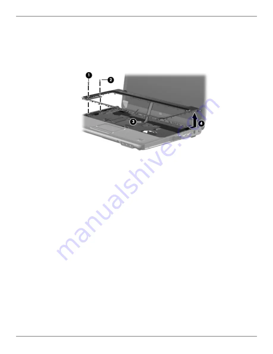
2. Turn the computer display-side up with the front toward you.

3. Open the computer as far as possible.

4. Remove the Phillips PM2.5×8.0 screw 

1

 and the Phillips PM2.5×4.0 screw 

2

 securing the keyboard cover to 

the top cover.

5. Disconnect the LED board cable 

3

.

6. Release the keyboard cover 

4

 by sliding it toward the display assembly until it disengages from the computer.

7. Remove the keyboard cover.

Reverse this procedure to install the keyboard cover.

Summary of Contents for Pavilion dv4

Page 1: ... Part Number 598157 001 December 2009 This guide is a troubleshooting reference used for maintaining and servicing the computer It provides comprehensive information on identifying computer features components and spare parts troubleshooting computer problems and performing computer disassembly procedures ...

Page 2: ...d Windows are U S registered trademarks of Microsoft Corporation SD Logo is a trademark of its proprietor The information contained herein is subject to change without notice The only warranties for HP products and services are set forth in the express warranty statements accompanying such products and services Nothing herein should be construed as constituting an additional warranty HP shall not ...

Page 3: ...t allow another hard surface such as an adjoining optional printer or a soft surface such as pillows or rugs or clothing to block airflow Also do not allow the AC adapter to contact the skin or a soft surface such as pillows or rugs or clothing during operation The computer and the AC adapter comply with the user accessible surface temperature limits defined by the International Standard for Safet...

Page 4: ...Display 2 5 Front components 2 6 Rear component 2 7 Right side components 2 8 Left side components 2 9 Bottom components 2 10 Wireless antennas 2 11 Additional hardware components 2 12 3 Illustrated parts catalog Service tag 3 1 Computer major components 3 2 Display assembly subcomponents 3 9 Plastics Kit 3 10 Mass storage devices 3 11 Miscellaneous parts 3 12 Sequential part number listing 3 14 ...

Page 5: ...ttery 4 12 TV tuner 4 14 WLAN module 4 15 Optical drive 4 19 Keyboard 4 20 Keyboard cover 4 23 Power button board 4 25 Speaker assembly 4 26 Display assembly 4 27 Webcam microphone module 4 33 Top cover 4 34 Touchpad button board and bracket 4 37 Fingerprint Reader board select models only 4 39 Modem module select models only 4 40 Bluetooth module select models only 4 42 Audio board 4 44 USB board...

Page 6: ...s 6 1 14 1 inch WXGA BrightView display specifications 6 2 Hard drive specifications 6 3 Blu ray DVD R RW SuperMulti Double Layer Drive with LightScribe specifications 6 4 DVD RW SuperMulti Double Layer Combo Drive with LightScribe specifications 6 5 System DMA specifications 6 6 System interrupt specifications 6 7 System I O address specification 6 8 7 Backup and recovery Overview 7 1 Creating re...

Page 7: ...one 8 1 External monitor 8 2 HDMI 8 3 RJ 11 modem select models only 8 4 RJ 45 network 8 5 Universal Serial Bus 8 6 9 Power cord set requirements Requirements for all countries and regions 9 1 Requirements for specific countries and regions 9 2 10Recycling Battery 10 1 Display 10 1 Index ...

Page 8: ...Up to 268 MB of video memory on computer models equipped with 1 GB of main system memory Up to 781 MB of video memory on computer models equipped with 2 GB of main system memory Up to 1292 MB of video memory on computer models equipped with 3GB of main system memory Up to 1293 MB of video memory on computer models equipped with 4GB of main system memory 32 bit OS Up to 1759 MB of video memory on c...

Page 9: ...system memory 1024 1 Hard Drives Supports a 9 50 mm 6 35 cm 2 50 in hard drive Supports HP ProtectSmart Hard Drive Protection Customer accessible Serial ATA Supports the following hard drives 500 GB 7200 rpm 320 GB 7200 rpm 250 GB 7200 rpm 160 GB 7200 rpm Optical drives 12 7 mm tray load Serial ATA SATA MultiBay weight saver Customer accessible Supports the following drives Blu ray ROM DVD R RW Su...

Page 10: ...Broadcom BCM2070 Bluetooth 2 1 module select models only External media cards One ExpressCard slot supporting optional ExpressCard 54 cards Digital Media Slot supporting Memory Stick MS Memory Stick Pro MSP MultiMediaCard MMC Secure Digital SD Memory Card and xD Picture Card XD Adapter purchased separately provides support for mini versions of SD MMC and MSP Duo Ports Audio in stereo microphone Au...

Page 11: ...ized cable plug support Battery options 3 cell 4 40 Ah 47 Wh Li ion battery 6 cell 2 20 Ah 47 Wh Li ion battery 6 cell 2 20 Ah 55 Wh Li ion battery 6 cell 2 55 Ah 55 Wh Li ion battery 12 cell 2 20 Ah 95 Wh Li ion battery Security Kensington Security Lock Fingerprint Reader with Digital Persona Software Support select models only Operating system Preinstalled Windows 7 Professional 32 and 64 bit OS...

Page 12: ... Component Description 1 TouchPad light White TouchPad is enabled Amber TouchPad is disabled 2 TouchPad Moves the pointer and selects or activates items on the screen 3 Left TouchPad button Functions like the left button on an external mouse 4 TouchPad On Off button Enables disables the TouchPad 5 TouchPad vertical scroll zone Scrolls up or down 6 Right TouchPad button Functions like the right but...

Page 13: ...drive is being accessed On HP ProtectSmart Hard Drive Protection has temporarily parked the internal hard drive and if present the hard drive in the SmartBay 4 Caps lock light On The caps lock is on 5 Volume Mute light White The computer sound is on Amber The computer sound is off 6 Volume Down light On Decreases speaker volume 7 Volume Up light On Increases speaker volume 8 Num lock light On The ...

Page 14: ... computer To learn more about power settings select Start Control Panel System and Security Power Options 3 Volume Mute button Mutes and restores speaker sound 4 Volume Scroll zone Adjusts speaker volume To decrease volume slide your finger to the left or tap the minus sign on the scroll zone To increase volume slide your finger to the right or tap the plus sign on the scroll zone 5 Wireless butto...

Page 15: ...uently used system functions when pressed at the same time as a function key or the esc key 3 Windows Logo key Displays the Windows Start menu 4 Windows Applications key Displays a shortcut menu for items beneath the pointer 5 Embedded numeric keypad keys Used like the keys on an external numeric keypad 6 Function keys Executes frequently used system functions when pressed at the same time as the ...

Page 16: ... Item Component Description 1 Internal display switch Turns off the display if the display is closed while the computer is on 2 Internal digital dual array microphones 2 Records sound 3 Webcam light On The webcam is in use 4 Webcam Records video and captures still photographs ...

Page 17: ...If the computer is not connected to an external power source the light is off until the battery reaches a low battery level 3 Drive light Flashing The hard drive or the optical drive is being accessed On The HP ProtectSmart Hard Drive Protection has temporarily parked the internal hard drive and if present the hard drive in the SmartBay 4 Consumer infrared lens Receives a signal from the HP Remote...

Page 18: ...ide 2 7 Rear component Component Description Vent Enables airflow to cool internal components The computer fan starts automatically to cool internal components and prevent overheating It is normal for the internal fan to cycle on and off during routine operation ...

Page 19: ...ntification Right side components Item Component Description 1 SmartBay Supports an optical drive or hard drive 2 USB ports 2 Connects optional USB devices 3 RJ 11 modem jack select models only Connects a modem cable 4 Power connector Connects an AC adapter ...

Page 20: ... has only one expansion port The term expansion port 3 describes the type of expansion port 4 RJ 45 network jack Connects a network cable 5 HDMI port Connects an optional video or audio device such as a high definition television or any compatible digital or audio component 6 eSATA USB port Connects high performance eSATA components such as an eSATA external hard drive or connects an optional USB ...

Page 21: ...nents The computer fan starts automatically to cool internal components and prevent overheating It is normal for the internal fan to cycle on and off during routine operation 7 Hard Drive bay Holds the hard drive and the wireless LAN WLAN device Ä To prevent an unresponsive system replace the wireless module only with a wireless module authorized for use in the computer by the governmental agency ...

Page 22: ... section of Regulatory Safety and Environmental Notices chapter in Help and Support Component Description WLAN antennas 2 Send and receive wireless signals to communicate with wireless networks The antennas are not visible from the outside of the computer For optimal transmission keep the areas immediately around the antennas free from obstructions ...

Page 23: ...ware components Item Component Description 1 Power cord Connects an AC adapter to an AC outlet 2 AC adapter Converts AC power to DC power 3 Battery Powers the computer when the computer is not connected to external power Batteries and power cords vary in appearance by country or region ...

Page 24: ... the computer 2 Serial number s n An alphanumeric identifier that is unique to each product 3 Part number Product number p n This number provides specific information about the product s hardware components The part number helps a service technician to determine which components and parts are needed 4 Model description An alphanumeric identifier used to locate documents drivers and support for the...

Page 25: ...3 2 Maintenance and Service Guide Illustrated parts catalog Computer major components ...

Page 26: ...dels 594112 001 14 1 in WXGA BrightView display assembly with wireless mobile broadband for use with plaid computer models 594112 002 2 Keyboard includes keyboard cable For use with black computer models in Brazil 518793 201 French Canada 518787 121 Japan 518793 291 Latin America 518793 161 South Korea 518793 AD1 Taiwan 518793 AB1 Thailand 518793 281 the United States 518793 001 For use with black...

Page 27: ...replacement thermal material UMA graphics subsystems 591957 001 Discrete graphics subsystems 591956 001 7 Speaker assembly All countries and regions except India 486837 001 India 486865 D61 8 System board includes replacement thermal material UMA graphics subsystems 590350 001 Discrete graphics subsystems 590349 001 Plastics Kit see Plastics Kit on page 3 10 for spare part component information 48...

Page 28: ...a Liechtenstein Lithuania Luxembourg Macedonia Madagascar Malawi Malaysia the Maldives Mali Malta the Marshall Islands Martinique Mauritania Mauritius Mexico Micronesia Monaco Mongolia Montenegro Morocco Mozambique Namibia Nauru Nepal the Nether Antilles the Netherlands New Zealand Nicaragua Niger Nigeria Norway Oman Pakistan Palau Panama Papua New Guinea Paraguay the People s Republic of China Pe...

Page 29: ...n Kazakhstan Kenya Kiribati Kuwait Kyrgyzstan Laos Latvia Lebanon Lesotho Liberia Liechtenstein Lithuania Luxembourg Macedonia Madagascar Malawi Malaysia the Maldives Mali Malta the Marshall Islands Martinique Mauritania Mauritius Mexico Micronesia Monaco Mongolia Montenegro Morocco Mozambique Namibia Nauru Nepal the Nether Antilles the Netherlands New Zealand Nicaragua Niger Nigeria Norway Oman P...

Page 30: ...the Ivory Coast Jamaica Japan Jordan Kazakhstan Kenya Kiribati Kuwait Kyrgyzstan Laos Latvia Lebanon Lesotho Liberia Liechtenstein Lithuania Luxembourg Macedonia Madagascar Malawi Malaysia the Maldives Mali Malta the Marshall Islands Martinique Mauritania Mauritius Mexico Micronesia Monaco Mongolia Montenegro Morocco Mozambique Namibia Nauru Nepal the Nether Antilles the Netherlands New Zealand Ni...

Page 31: ... 484171 001 6 cell Li Ion 2 2 Ah 47 Wh 484170 001 3 cell Li Ion 4 4 Ah 47 Wh 516915 001 22 Base enclosure 486848 001 23 Optical drive includes bezel and bracket DVD R RW SuperMulti DL Drive with LightScribe 482177 001 Blu ray ROM DVD R RW SuperMulti DL Drive with LightScribe 508123 001 24 Hard Drive includes hard drive bracket for hard drive spare part component information see Mass storage device...

Page 32: ... 001 4 Display hinge kit 486894 001 5 Display inverter 486736 001 6a Display cable 486878 001 6b Wireless antenna 594105 001 Wireless antenna cables 489068 001 7 Display enclosure includes logo light and cables Black computer models 518799 001 White computer models 518825 001 Plaid computer models 573188 001 Display Rubber Kit contains all rubber pieces for the display bezel 486874 001 Internal di...

Page 33: ...e Illustrated parts catalog Plastics Kit Item Description Spare part number Plastics Kit 486833 001 1 Hard Drive cover includes two captive screws 2 Memory Module compartment cover 3 Mini Card compartment cover 4 ExpressCard slot bezel ...

Page 34: ...GB 7200 rpm 575568 001 250 GB 7200 rpm 575567 001 160 GB 7200 rpm 580846 001 Hard Drive Hardware Kit Hard Drive Hardware Kit 482158 001 Hard Drive Hardware Kit MultiBay 488128 001 MultiBay blank 491876 001 2 Optical drive includes bezel and bracket DVD R RW SuperMulti DL Drive with LightScribe 482177 001 Blu ray ROM DVD R RW SuperMulti DL Drive with LightScribe 508123 001 not illustrated ...

Page 35: ...34 001 CAT5e network cable 454619 001 Wired headset with volume control 371693 001 Screw Kit includes all screws Phillips PM1 5 9 0 screws Phillips PM2 0 2 0 broadhead screws Phillips PM2 0 3 0 screws Phillips PM2 0 4 0 screws Phillips PM2 0 5 0 screws Phillips PM2 0 10 0 captive screws Phillips PM2 5 3 0 screws Phillips PM2 5 4 0 screws Phillips PM2 5 5 0 screws Phillips PM2 5 6 0 captive screws ...

Page 36: ...e Controls ExpressCard remote control 464793 002 Full function remote control 465540 001 Full function remote control for use with blue colored computer models 465540 002 Full function remote control with Teletext 465541 001 Full function remote control with Teletext for use with blue colored computer models 465541 002 Standard carrying case 418162 001 Description Spare part number ...

Page 37: ... remote control with Teletext for use with blue colored computer models 482158 001 Hard Drive Hardware Kit 482177 001 DVD R RW SuperMulti DL Drive with LightScribe 482899 001 ATSC NTSC TV tuner 482899 002 DVB T ANG Integrated TV tuner 482899 003 DVB T tuner 482899 004 DVB T tuner for use only in the AP region 482900 001 ATSC NTSC TV tuner antenna 482900 002 TV tuner antenna with PAL jack 483261 00...

Page 38: ... models with discrete graphics subsystems 489068 001 Wireless antenna cables 490371 001 Power cord for use in the United States 490371 011 Power cord for use in Australia 490371 021 Power cord for use in Europe 490371 031 Power cord for use in the United Kingdom and Singapore 490371 061 Power cord for use in Italy 490371 201 Power cord for use in Brazil 490371 291 Power cord for use in Japan 49037...

Page 39: ... with LightScribe 516915 001 3 cell Li Ion 4 4 Ah 47 Wh 518436 001 Atheros AR9285 802 11b g n for use in Canada the Cayman Islands Guam Puerto Rico the United States and the U S Virgin Islands 518436 002 Atheros AR9285 802 11b g n for use in Afghanistan Albania Algeria Andorra Angola Antigua and Barbuda Argentina Armenia Aruba Australia Austria Azerbaijan the Bahamas Bahrain Barbados Belgium Beliz...

Page 40: ... Slovenia the Solomon Islands Somalia South Africa South Korea Spain Sri Lanka St Kitts and Nevis St Lucia St Vincent and the Grenadines Suriname Swaziland Sweden Switzerland Syria Taiwan Tajikistan Tanzania Thailand Togo Tonga Trinidad and Tobago Tunisia Turkey Turkmenistan Tuvalu Uganda the United Arab Emirates the United Kingdom Uruguay Uzbekistan Vanuatu Venezuela Vietnam Yemen Zaire Zambia an...

Page 41: ...hout a Fingerprint Reader includes TouchPad and cable 591951 001 Top cover for use only in white computer models with a Fingerprint Reader includes TouchPad and cable 591952 001 Top cover for use only in black computer models without a Fingerprint Reader includes TouchPad and cable 591953 001 Top cover for use only in black computer models with a Fingerprint Reader includes TouchPad and cable 5919...

Page 42: ...reless mobile broadband for use with plaid computer models 594187 001 Intel Arrandale Single Core i5 520M processor 2 4 GHz 3 MB L3 cache 1066 MHZ SC Turbo 594188 001 Intel Arrandale Single Core i5 540M processor 2 53 GHz 3 MB L3 cache 1066 MHZ SC Turbo 594532 001 Keyboard cover plaid models Spare part number Description ...

Page 43: ...cessive force during disassembly and reassembly damages plastic parts Use care when handling the plastic parts Apply pressure only at the points designated in the maintenance instructions Cables and connectors ÄCAUTION When servicing the computer be sure that cables are placed in their proper locations during the reassembly process Improper cable placement damages the computer Cables must be handl...

Page 44: ...ailer or other suitable form of protective packaging and label the package FRAGILE Grounding guidelines Electrostatic discharge damage Electronic components are sensitive to electrostatic discharge ESD Circuitry design and structure determine the degree of sensitivity Networks built into many integrated circuits provide some protection but in many cases ESD contains enough power to alter device pa...

Page 45: ...ot possible use an ionizer to dissipate electric charges Workstation guidelines Follow these grounding workstation guidelines Cover the workstation with approved static shielding material Use a wrist strap connected to a properly grounded work surface and use properly grounded tools and equipment Use conductive field service tools such as cutters screwdrivers and vacuums When fixtures must directl...

Page 46: ...ps on both feet with a minimum of one megohm resistance between the operator and ground To be effective the conductive strips must be worn in contact with the skin The following grounding equipment is recommended to prevent electrostatic damage Antistatic tape Antistatic smocks aprons and sleeve protectors Conductive bins and other assembly or soldering aids Nonconductive foam Conductive tabletop ...

Page 47: ...he computer serial number and model description provided on the service tag Item Component Description 1 Product name The name affixed to the front of the computer 2 Serial number s n An alphanumeric identifier that is unique to each product 3 Part number Product number p n This number provides specific information about the product s hardware components The part number helps a service technician ...

Page 48: ...eplacement procedures Computer feet The computer feet are adhesive backed rubber pads The feet are included in the Rubber Kit spare part number 486874 001 There are six rubber feet that attach to the base enclosure in the locations illustrated below ...

Page 49: ...ng the AC adapter from the computer Remove the battery 1 Turn the computer upside down on a flat surface with the battery bay toward you 2 Slide the battery release latch 1 to release the battery 3 Pivot the battery 2 upward and lift it out of the computer 3 To insert the battery insert the rear edge of the battery into the battery bay and pivot the front edge downward until the battery is seated ...

Page 50: ...e computer with the front toward you 2 Remove the two Phillips PM2 5 6 0 captive screws 1 that secure the hard drive cover to the computer 3 Lift the left side 2 of the hard drive cover swing it to the right and remove the cover 3 The hard drive cover is included in the Plastics Kit spare part number 486833 001 4 Remove the three Phillips PM2 0 4 0 screws 1 that secure the hard drive to the comput...

Page 51: ...4 9 7 If it is necessary to replace the hard drive bracket a Remove the two Phillips PM3 0 3 0 screws 1 from each side of the hard drive b Lift the bracket 2 straight up to remove it from the hard drive Reverse this procedure to reassemble and install the hard drive ...

Page 52: ...apter from the computer 4 Remove the battery see Battery on page 4 7 The top memory module slot is for expansion memory and the bottom slot is for primary memory Remove the memory module 1 Position the computer with the front toward you 2 Remove the Phillips PM2 5 6 0 captive screw 1 that secures the memory module compartment cover to the computer 3 Lift the right side of the cover 2 swing it to t...

Page 53: ...ry module to release the memory module The edge of the module opposite the slot rises away from the computer 5 Remove the memory module by sliding the module to the right 2 Memory modules are designed with a notch 3 to prevent incorrect insertion into the memory module slot Reverse this procedure to install the memory module ...

Page 54: ...onnected to the computer 3 Disconnect the power from the computer by first disconnecting the power cord from the AC outlet and then disconnecting the AC adapter from the computer 4 Remove the battery see Battery on page 4 7 Remove the RTC battery 1 Remove the two Phillips PM2 5 6 0 captive screws 1 that secure the Mini Card compartment cover to the computer 2 Lift the right side of the Mini Card c...

Page 55: ...moval and replacement procedures Maintenance and Service Guide 4 13 3 Disconnect the RTC battery cable 1 from the system board 4 Remove the RTC battery 2 Reverse this procedure to install the RTC battery ...

Page 56: ...4 Remove the battery see Battery on page 4 7 5 Remove the Mini Card compartment cover see RTC battery on page 4 12 Remove the TV tuner 1 Disconnect the TV tuner cable 1 from the system board 2 Remove the two Phillips PM2 0 5 0 screws 2 and slide the TV tuner to the left 3 to remove it Memory modules are designed with a notch to prevent incorrect insertion into the TV tuner slot Reverse this proced...

Page 57: ...ates the United Kingdom Uruguay Uzbekistan Vanuatu Venezuela Vietnam Yemen Zaire Zambia and Zimbabwe 504593 004 Atheros AR9285 802 11b g n for use in Canada the Cayman Islands Guam Puerto Rico the United States and the U S Virgin Islands 518436 001 Atheros AR9285 802 11b g n for use in Afghanistan Albania Algeria Andorra Angola Antigua and Barbuda Argentina Armenia Aruba Australia Austria Azerbaij...

Page 58: ...n Kenya Kiribati Kuwait Kyrgyzstan Laos Latvia Lebanon Lesotho Liberia Liechtenstein Lithuania Luxembourg Macedonia Madagascar Malawi Malaysia the Maldives Mali Malta the Marshall Islands Martinique Mauritania Mauritius Mexico Micronesia Monaco Mongolia Montenegro Morocco Mozambique Namibia Nauru Nepal the Nether Antilles the Netherlands New Zealand Nicaragua Niger Nigeria Norway Oman Palau Panama...

Page 59: ...egulates wireless devices in your country or region If you replace the module and then receive a warning message remove the module to restore computer functionality and then contact technical support through Help and Support 1 Remove the hard drive cover see Hard Drive on page 4 8 2 Position the computer with the front toward you 3 Disconnect the WLAN antenna cables 1 from the terminals on the WLA...

Page 60: ...Removal and replacement procedures 6 If it is necessary to replace the Mini Card bracket remove the two Phillips PM2 0 5 0 screws 1 and then slide 2 the bracket to the right to remove it Reverse this procedure to install the WLAN module ...

Page 61: ... to the computer 3 Disconnect the power from the computer by first disconnecting the power cord from the AC outlet and then disconnecting the AC adapter from the computer 4 Remove the battery see Battery on page 4 7 Remove the optical drive 1 Position the computer with the right side toward you 2 Slide the release latch 1 away from the battery bay 3 Remove the optical drive 2 Reverse this procedur...

Page 62: ... RTC battery on page 4 12 7 Remove the optical drive see Optical drive on page 4 19 Description Spare part number Black computer models textured in Brazil 570755 201 French Canada 570755 121 Japan 570755 291 Latin America 570755 161 South Korea 570755 AD1 Taiwan 570755 AB1 Thailand 570755 281 the United States 570755 001 Black computer models in Brazil 518793 201 French Canada 518787 121 Japan 518...

Page 63: ...e the keyboard to the computer 2 Turn the computer display side up with the front toward you 3 Open the computer as far as possible 4 Lift the rear edge of the keyboard 1 until it rests at an angle The keyboard is secured by double sided tape 5 Slide the keyboard 2 back until the tabs on the bottom of the keyboard are clear of the keyboard cover ...

Page 64: ...and replacement procedures 6 Release the zero insertion force ZIF connector 1 to which the keyboard cable is attached and disconnect the keyboard cable 2 from the system board 7 Remove the keyboard Reverse this procedure to install the keyboard ...

Page 65: ... the AC outlet and then disconnecting the AC adapter from the computer 4 Remove the battery see Battery on page 4 7 5 Remove the following components a Hard Drive cover see Hard Drive on page 4 8 b Mini Card compartment cover see RTC battery on page 4 12 c Optical drive see Optical drive on page 4 19 d Keyboard see Keyboard on page 4 20 Remove the keyboard cover 1 Remove the two Phillips PM2 5 8 0...

Page 66: ... as possible 4 Remove the Phillips PM2 5 8 0 screw 1 and the Phillips PM2 5 4 0 screw 2 securing the keyboard cover to the top cover 5 Disconnect the LED board cable 3 6 Release the keyboard cover 4 by sliding it toward the display assembly until it disengages from the computer 7 Remove the keyboard cover Reverse this procedure to install the keyboard cover ...

Page 67: ...from the computer 4 Remove the battery see Battery on page 4 7 5 Remove the following components a Hard Drive see Hard Drive on page 4 8 b Mini Card compartment cover see RTC battery on page 4 12 c Optical drive see Optical drive on page 4 19 d Keyboard see Keyboard on page 4 20 e Keyboard cover see Keyboard cover on page 4 23 Remove the power button board 1 Disconnect the power button board cable...

Page 68: ...rive cover see Hard Drive on page 4 8 b Mini Card compartment cover see RTC battery on page 4 12 c Optical drive cover see Optical drive on page 4 19 d Keyboard see Keyboard on page 4 20 e Keyboard cover see Keyboard cover on page 4 23 Remove the speaker assembly 1 Disconnect the display lid switch 1 from the system board 2 Remove the two Phillips PM2 5 3 0 screws 2 that secure the speaker assembl...

Page 69: ...ove the following components a Hard Drive cover see Hard Drive on page 4 8 b Mini Card compartment cover see RTC battery on page 4 12 c Optical drive see Optical drive on page 4 19 d Keyboard see Keyboard on page 4 20 e Keyboard cover see Keyboard cover on page 4 23 f Speaker assembly see Speaker assembly on page 4 26 Description Spare part number 14 1 in WXGA BrightView display assembly for use w...

Page 70: ...the display as far as possible 3 Remove the wireless antenna cable from the routing channels and clips 1 and disconnect it from the base enclosure 2 4 Disconnect the display cable 3 from the system board 5 Remove the two Phillips PM2 5 5 0 screws 1 and the two Phillips PM2 5 8 0 screws 2 that secure the display assembly to the computer 6 Remove the display assembly 3 ...

Page 71: ...emove the Mylar screw covers 1 and the two Phillips PM2 5 5 0 screws 2 on the display bezel lower edge The display mylar screw covers are included in the Display Rubber Kit spare part number 486874 001 8 Flex the inside edges of the top edge 1 the left and right sides 2 and the bottom edge 3 of the display bezel until the bezel disengages from the display enclosure 9 Remove the display bezel 4 The...

Page 72: ...cable 2 and the backlight cable 3 from the display inverter The display inverter is available using spare part number 486736 001 12 Remove the four Phillips PM2 5 5 0 screws 1 and the four Phillips PM2 5 3 0 screws 2 that secure the display panel to the display enclosure 13 Lift the display panel 3 out of the display enclosure and disconnect the display panel cable 4 The display panel is available...

Page 73: ...play d Remove the cable from the display 4 This also includes the webcam and LED cables The display cable is available using spare part number 486878 001 15 Replace the display hinges remove the eight Phillips PM2 0 3 0 screws 1 that secure the hinges to the display panel Remove the screws in the sequence indicated on the display hinge bracket 16 Remove the display hinges 2 The display hinges are ...

Page 74: ...ntenna transceivers 2 from the display enclosure The transceivers are secured by a foil wrapping 19 Remove the wireless antenna transceivers and cables from the clips 3 built into the display enclosure 20 Remove the wireless antenna transceivers and cables 4 from the display enclosure The wireless antenna transceivers and cables are available using spare part number 489068 001 Reverse this procedu...

Page 75: ...les from the WLAN module see WLAN module on page 4 15 6 Remove the following components a Hard Drive cover see Hard Drive on page 4 8 b Mini Card compartment cover see RTC battery on page 4 12 c Optical drive see Optical drive on page 4 19 d Keyboard see Keyboard on page 4 20 e Keyboard cover see Keyboard cover on page 4 23 f Speaker assembly see Speaker assembly on page 4 26 g Display assembly se...

Page 76: ...ge 4 7 5 Remove the following components a Hard Drive see Hard Drive on page 4 8 b Mini Card compartment cover see RTC battery on page 4 12 c Optical drive see Optical drive on page 4 19 d Keyboard see Keyboard on page 4 20 e Keyboard cover see Keyboard cover on page 4 23 f Speaker assembly see Speaker assembly on page 4 26 g Display assembly see Display assembly on page 4 27 Description Spare par...

Page 77: ...e following screws that secure the top cover to the base enclosure 1 Three Phillips PM2 5 8 0 screws 2 Three Phillips PM2 5 5 0 screws 3 One Phillips PM2 5 3 0 screw 3 Turn the computer right side up with the front toward you 4 Disconnect the following cables from the system board 1 TouchPad cable 2 Fingerprint Reader board cable select models only 3 USB cable ...

Page 78: ...emove the three Phillips PM2 5 3 0 screws 1 and the Phillips PM2 5 8 0 screw 2 that secure the top cover to the base enclosure 6 Lift up the front edge of the top cover until it releases from the base 3 7 Remove the top cover 4 Reverse this procedure to install the top cover ...

Page 79: ... first disconnecting the power cord from the AC outlet and then disconnecting the AC adapter from the computer 4 Remove the battery see Battery on page 4 7 5 Remove the following components a Hard Drive see Hard Drive on page 4 8 b Mini Card compartment cover see RTC battery on page 4 12 c Optical drive see Optical drive on page 4 19 d Keyboard see Keyboard on page 4 20 e Keyboard cover see Keyboa...

Page 80: ...n the top cover upside down with the front toward you 2 Disconnect the touchpad cable 1 from the top cover 3 Remove four Phillips PM2 5 3 0 screws 2 4 Remove one Phillips PM2 5 4 0 screw 3 5 Lift up 4 and remove the touchpad button board and bracket Reverse this procedure to install the touchpad button board and bracket ...

Page 81: ...Hard Drive see Hard Drive on page 4 8 b Mini Card compartment cover see RTC battery on page 4 12 c Optical drive see Optical drive on page 4 19 d Keyboard see Keyboard on page 4 20 e Keyboard cover see Keyboard cover on page 4 23 f Speaker assembly see Speaker assembly on page 4 26 g Display assembly see Display assembly on page 4 27 h Top cover see Top cover on page 4 34 Remove the Fingerprint Re...

Page 82: ...ng the AC adapter from the computer 4 Remove the battery see Battery on page 4 7 5 Remove the following components a Hard Drive see Hard Drive on page 4 8 b Mini Card compartment cover see RTC battery on page 4 12 c WLAN module see WLAN module on page 4 15 d Optical drive see Optical drive on page 4 19 e Keyboard see Keyboard on page 4 20 f Keyboard cover see Keyboard cover on page 4 23 g Speaker ...

Page 83: ...t the modem module cable 1 from the modem module 2 Remove the two Phillips PM2 0 4 0 screws 2 that secure the modem module to the system board 3 Lift up on the back of the modem module 3 to disconnect it from the system board 4 Remove the modem module Reverse the above procedure to install the modem module ...

Page 84: ...the AC adapter from the computer 4 Remove the battery see Battery on page 4 7 5 Remove the following components a Hard Drive see Hard Drive on page 4 8 b Mini Card compartment cover see RTC battery on page 4 12 c WLAN module see WLAN module on page 4 15 d Optical drive see Optical drive on page 4 19 e Keyboard see Keyboard on page 4 20 f Keyboard cover see Keyboard cover on page 4 23 g Speaker ass...

Page 85: ...over upside down with the front toward you 2 Lift the Bluetooth module 1 from the the computer 3 Disconnect the Bluetooth module cable 2 from the Bluetooth module and system board 4 Remove the tape 3 that secures the cable and then remove the Bluetooth module and cable 4 Reverse this procedure to install the Bluetooth module ...

Page 86: ...then disconnecting the AC adapter from the computer 4 Remove the battery see Battery on page 4 7 5 Remove the following components a Hard Drive see Hard Drive on page 4 8 b Mini Card compartment cover see RTC battery on page 4 12 c Mini Card bracket see WLAN module on page 4 15 d Optical drive see Optical drive on page 4 19 e Keyboard see Keyboard on page 4 20 f Keyboard cover see Keyboard cover o...

Page 87: ... 2 Release the audio board cable 2 from the base enclosure 3 Remove the two Phillips PM2 5 3 0 screws 3 that secure the audio board to the system board 4 Lift the rear edge of the audio board 4 so that the audio connectors slide out of the openings in the base enclosure and then remove the audio board and cable Reverse this procedure to install the audio board ...

Page 88: ...then disconnecting the AC adapter from the computer 4 Remove the battery see Battery on page 4 7 5 Remove the following components a Hard Drive see Hard Drive on page 4 8 b Mini Card compartment cover see RTC battery on page 4 12 c Mini Card bracket see WLAN module on page 4 15 d Optical drive see Optical drive on page 4 19 e Keyboard see Keyboard on page 4 20 f Keyboard cover see Keyboard cover o...

Page 89: ... with the right side toward you 2 Disconnect the USB board cable 1 from the system board 3 Remove the cable 2 from the base enclosure clips 4 Remove the Phillips PM2 5 3 0 screw 3 that secures the USB board to the computer 5 Lift the USB board 4 straight up to remove it from the computer Reverse this procedure to install the USB board ...

Page 90: ...connecting the AC adapter from the computer 4 Remove the battery see Battery on page 4 7 5 Remove the following components a Hard Drive see Hard Drive on page 4 8 b Mini Card compartment cover see RTC battery on page 4 12 c WLAN module see WLAN module on page 4 15 d Optical drive see Optical drive on page 4 19 e Keyboard see Keyboard on page 4 20 f Keyboard cover see Keyboard cover on page 4 23 g ...

Page 91: ...ht side up 2 Position the computer with the right side toward you 3 Remove the power connector 1 from the clip built into the base enclosure The power connector is secured by double sided tape 4 Disconnect the power connector cable 2 from the base enclosure Reverse this procedure to install the power connector and cable ...

Page 92: ...move the battery see Battery on page 4 7 5 Remove the following components a Hard Drive see Hard Drive on page 4 8 b Memory module see Memory module on page 4 10 c Mini Card compartment cover see RTC battery on page 4 12 d WLAN module see WLAN module on page 4 15 e Optical drive see Optical drive on page 4 19 f Keyboard see Keyboard on page 4 20 g Keyboard cover see Keyboard cover on page 4 23 h S...

Page 93: ... system board and installed on the replacement system board Heat sink assembly see Heat sink assembly on page 4 55 Processor see Processor on page 4 59 Remove the system board 1 Turn the computer display side up with the right side toward you 2 Disconnect the following cables from the system board 1 Modem cable 2 Audio board cable 3 Fan cable 3 Disconnect the power connector cable ...

Page 94: ... board to the computer 5 Use the optical drive connector 1 to lift the right side of the system board 2 until it rests at an angle 6 Release the system board 3 by sliding it to the right at an angle until the connectors on the left side of the system board disengage from the base enclosure and then remove the system board Reverse this procedure to install the system board ...

Page 95: ...e battery see Battery on page 4 7 5 Remove the following components a Hard Drive see Hard Drive on page 4 8 b Memory module see Memory module on page 4 10 c Mini Card compartment cover see RTC battery on page 4 12 d WLAN module see WLAN module on page 4 15 e Optical drive see Optical drive on page 4 19 f Keyboard see Keyboard on page 4 20 g Keyboard cover see Keyboard cover on page 4 23 h Speaker ...

Page 96: ... procedures Remove the RJ 11 connector 1 Remove the RJ 11 connector 1 from the clip built into the base enclosure 2 Remove the RJ 11 connector cable 2 from the routing channel built into the base enclosure Reverse this procedure to install the RJ 11 connector ...

Page 97: ...see Battery on page 4 7 5 Remove the following components a Hard Drive see Hard Drive on page 4 8 b Memory module see Memory module on page 4 10 c Mini Card compartment cover see RTC battery on page 4 12 d WLAN module see WLAN module on page 4 15 e Optical drive see Optical drive on page 4 19 f Keyboard see Keyboard on page 4 20 g Keyboard cover see Keyboard cover on page 4 23 h Speaker assembly s...

Page 98: ...l located between the heat sink assembly and system board components it might be necessary to move the heat sink assembly from side to side to detach the assembly The thermal material must be thoroughly cleaned from the surface of the heat sink assembly and the system board each time the heat sink assembly is removed Thermal material is applied to the heat sink to correspond with components on the...

Page 99: ...n the computer on and then shut it down through the operating system 2 Disconnect all external devices connected to the computer 3 Disconnect the power from the computer by first disconnecting the power cord from the AC outlet and then disconnecting the AC adapter from the computer 4 Remove the battery see Battery on page 4 7 5 Remove the following components a Hard Drive see Hard Drive on page 4 ...

Page 100: ...ment procedures Remove the fan 1 Position the base enclosure with the front toward you 2 Remove the two black Phillips PM2 5 5 0 screws 1 that secure the fan to the computer 3 Lift the fan from the base enclosure 2 Reverse this procedure to install the fan ...

Page 101: ...ove the following components a Hard Drive see Hard Drive on page 4 8 b Memory module see Memory module on page 4 10 c RTC battery see RTC battery on page 4 12 d WLAN module see WLAN module on page 4 15 e Optical drive see Optical drive on page 4 19 f Keyboard see Keyboard on page 4 20 g Keyboard cover see Keyboard cover on page 4 23 h Speaker assembly see Speaker assembly on page 4 26 i Display as...

Page 102: ...turn the processor locking screw 1 one half turn counterclockwise until you hear a click 2 Lift the processor 2 straight up and remove it When installing the processor align the gold triangle 3 on the processor must be aligned with the triangle 4 embossed on the processor socket Reverse this procedure to install the processor ...

Page 103: ...up Utility Changing the language of Setup Utility The following procedure explains how to change the language of Setup Utility If Setup Utility is not already running begin at step 1 If Setup Utility is already running begin at step 2 1 Open Setup Utility by turning on or restarting the computer When the Press the ESC key for Startup Menu message appears in the lower left corner of the screen pres...

Page 104: ...ssage appears in the lower left corner of the screen press the esc key When the Startup Menu is displayed press the f10 key 2 Select the Main menu 3 To exit Setup Utility without changing any settings use the arrow keys to select Exit Exit Discarding Changes and then press the enter key Restoring default settings in Setup Utility The following procedure explains how to restore Setup Utility defaul...

Page 105: ...arrow keys to select Exit Exit Discarding Changes and then press the enter key After either choice the computer restarts in Windows Setup Utility menus The menu tables in this section provide an overview of Setup Utility options Some of the Setup Utility menu items listed in this chapter might not be supported by the computer Main menu Security menu Select To Do This System information View and ch...

Page 106: ...on Boot Options Set the following boot options POST power on self test f10 and f12 delay seconds Set the delay for the f10 and f12 functions of Setup Utility in intervals of 5 seconds each 0 5 10 15 20 HP Guide QuickWeb Enable disable the HP QuickWeb boot menu during POST Delay to boot Windows set the delay for the HP QuickWeb boot menu to 2 3 10 15 or 30 seconds CD ROM boot Enable disable boot fr...

Page 107: ...18 5 V dc Operating current 3 5 A Temperature Operating not writing to optical disc 0 C to 35 C 32 F to 95 F Operating writing to optical disc 5 C to 35 C 41 F to 95 F Nonoperating 20 C to 60 C 4 F to 140 F Relative humidity Operating 10 to 90 Nonoperating 5 to 95 Maximum altitude unpressurized Operating 15 m to 3 048 m 50 ft to 10 000 ft Nonoperating 15 m to 12 192 m 50 ft to 40 000 ft Applicable...

Page 108: ...h 18 98 cm 7 47 in Diagonal 35 82 cm 14 10 in Number of colors More than 262 144 Contrast ratio More than 300 1 Brightness 200 nits typical Pixel resolution Pitch 0 2373 0 2373 mm Format 1280 800 Configuration RGB vertical stripe Backlight CCFT Character display 80 25 Total power consumption 5 2 W Viewing angle 40 horizontal 15 35 vertical typical ...

Page 109: ...es typical read including setting Single track 7200 rpm 1 5 ms 1 5 ms 1 5 ms 1 5 ms Average 7200 rpm 11 0 ms 11 0 ms 11 0 ms 11 0 ms Maximum 7200 rpm 22 0 ms 22 0 ms 22 0 ms 22 0 ms Logical blocks 976 773 168 625 142 448 488 397 168 312 581 808 Disc rotational speed 7200 rpm 7200 rpm 7200 rpm 7200 rpm Operating temperature 0 C to 60 C 32 F to 140 F 1 GB 1 billion bytes when referring to hard drive...

Page 110: ...OM BD R BD RE CD R CD RW DVD R DVD R 9 DVD RW DVD R DVD R 9 DVD RW DVD RAM LightScribe Interface SATA Access time CD DVD BD Random 190 ms 190 ms 230 ms Max data transfer rate 24X CD ROM 3 600 KB sec 8X DVD ROM 10 800 KB sec 4X BD ROM 18 000 KB sec 16X CD R 1 200 KB sec 10X CD RW 1 500 KB sec 8X DVD R 10 800 KB sec 8X DVD RW 10 800 KB sec 8X DVD R 10 800 KB sec 6X DVD RW 8 100 KB sec 4X DVD R Dual ...

Page 111: ...DVD R DVD RW DVD R DVD RW DVD RAM CD R CD RW DVD R DVD RW DVD R DVD RW DVD RAM LightScribe Interface SATA Access time CD DVD Random 150 ms 160 ms Max data transfer rate 24X CD ROM 3 600 KB sec 8X DVD ROM 10 800 KB sec 24X CD R 3 600 KB sec 16X CD RW 2 400 KB sec 8X DVD R 10 800 KB sec 8x DVD RW 10 800 KB sec 8X DVD R 10 800 KB sec 6X DVD RW 8 100 KB sec 4X DVD R Dual Layer 5 400 KB sec 4X DVD R Du...

Page 112: ... and Service Guide Specifications System DMA specifications Hardware DMA System function DMA0 Reserve DMA1 Reserve DMA2 Reserve DMA3 Reserve DMA4 Direct memory access controller DMA5 Reserve DMA6 Reserve DMA7 Reserve ...

Page 113: ...ler IRQ16 Standard OpenHCD USB Host Controller IRQ17 PCI standard PCI to PCI bridge IRQ17 Standard Enhanced PCI to USB Host Controller IRQ18 Broadcom 4322AG 802 11a b g draft n Wi Fi Adapter IRQ18 PCI standard PCI to PCI bridge IRQ18 Standard OpenHCD USB Host Controller IRQ18 Standard OpenHCD USB Host Controller IRQ19 High Definition Audio Controller IRQ19 PCI standard PCI to PCI bridge IRQ19 Real...

Page 114: ...rd 101 102 key keyboard or Microsoft Natural PS 2 Keyboard with HP 070 071 System CMOS real time clock 072 073 Motherboard resources 080 080 Motherboard resources 081 08F Direct memory access controller 092 092 Motherboard resources 0A0 0A1 Programmable interrupt controller 0B0 0B1 Motherboard resources 0C0 0DF Direct memory access controller 0F0 0FE Numeric data processor 3B0 3BB PCI standard PCI...

Page 115: ... to PCI bridge 7000 7FFF PCI standard PCI to PCI bridge 8010 801F Standard AHCI 1 0 Serial ATA Controller 8030 8037 Standard AHCI 1 0 Serial ATA Controller 8038 803F Standard AHCI 1 0 Serial ATA Controller 8048 804B Standard AHCI 1 0 Serial ATA Controller 804C 804F Standard AHCI 1 0 Serial ATA Controller FD60 FD63 ENE CIR Receiver ...

Page 116: ...Creating system restore points operating system feature System restore points allow you to reverse undesirable changes to the computer by restoring the computer to an earlier state Recovering a program or driver Recovery Manager software feature This feature helps you reinstall a program or driver without performing a full system recovery Performing a full system recovery Recovery Manager software...

Page 117: ...high quality DVD R DVD R BD R writable Blu ray or CD R discs All these discs are purchased separately DVDs and BDs have a much higher capacity than CDs If using CDs up to 20 discs might be required whereas only a few DVDs or BDs are required Read write discs such as CD RW DVD RW double layer DVD RW and BD RE rewritable Blu ray discs are not compatible with the Recovery Manager software The compute...

Page 118: ...indow toolbar or menu bar by taking a screen shot of your settings The screen shot is a time saver if you have to reset your preferences To copy the screen and paste it into a word processing document 1 Display the screen 2 Copy the screen To copy only the active window press alt fn prt sc To copy the entire screen press fn prt sc 3 Open a word processing document and then select Edit Paste 4 Save...

Page 119: ...ning utilities or changing Windows settings See Help and Support Using system restore points When backing up your system you are creating a system restore point A system restore point allows you to save and name a snapshot of your hard drive at a specific point in time You can then recover back to that point if you want to reverse subsequent changes made to your system Recovering to an earlier res...

Page 120: ...reviously backed up HP recommends using HP Recovery Manager to create a set of recovery discs entire drive backup as soon as you set up the computer Recovery Manager software allows you to repair or restore the system if you experience system failure or instability Recovery Manager works from recovery discs or from a dedicated recovery partition select models only on the hard drive However if the ...

Page 121: ...t do not have a partition Use these discs to recover your operating system and software On some models a recovery can be performed from the partition on the hard drive accessed by pressing either the Start button or the f11 key This restores the computer to its factory condition To restore the system from the partition 1 Access Recovery Manager by either Selecting Start All Programs Recovery Manag...

Page 122: ...ntenance and Service Guide 8 1 8 Connector pin assignments Audio in microphone Pin Signal 1 Audio signal in 2 Audio signal in 3 Ground Pin Signal 1 Audio out left channel 2 Audio out right channel 3 Ground ...

Page 123: ...gnments External monitor Pin Signal 1 Red analog 2 Green analog 3 Blue analog 4 Not connected 5 Ground 6 Ground analog 7 Ground analog 8 Ground analog 9 5 VDC 10 Ground 11 Monitor detect 12 DDC 2B data 13 Horizontal sync 14 Vertical sync 15 DDC 2B clock ...

Page 124: ... TDMS data 2 shield 3 TDMS data 2 4 TDMS data 1 5 TDMS data 1 shield 6 TDMS data 1 shield 7 TDMS data 0 8 TDMS data 0 shield 9 TDMS data 0 10 TDMS clock 11 TDMS data clock shield 12 TDMS data clock 13 Consumer electronics control 14 Not connected 15 Display data channel DDC clock 16 DDC data 17 Ground 18 5V Power 19 Hot plug detect ...

Page 125: ...8 4 Maintenance and Service Guide Connector pin assignments RJ 11 modem select models only Pin Signal 1 Unused 2 Tip 3 Ring 4 Unused 5 Unused 6 Unused ...

Page 126: ...Connector pin assignments Maintenance and Service Guide 8 5 RJ 45 network Pin Signal 1 Transmit 2 Transmit 3 Receive 4 Unused 5 Unused 6 Receive 7 Unused 8 Unused ...

Page 127: ...8 6 Maintenance and Service Guide Connector pin assignments Universal Serial Bus Pin Signal 1 5 VDC 2 Data 3 Data 4 Ground ...

Page 128: ...all countries and regions The requirements listed below are applicable to all countries and regions The length of the power cord set must be at least 1 5 m 5 0 ft and no more than 2 0 m 6 5 ft All power cord sets must be approved by an acceptable accredited agency responsible for evaluation in the country or region where the power cord set will be used The power cord sets must have a minimum curre...

Page 129: ...T 3 or equivalent No 18 AWG 3 conductor The wall plug must be a two pole grounding type with a NEMA 5 15P 15 A 125 V or NEMA 6 15P 15 A 250 V configuration 3 The appliance coupler flexible cord and wall plug must bear a T mark and registration number in accordance with the Japanese Dentori Law The flexible cord must be Type VCT or VCTF 3 conductor 1 00 mm conductor size The wall plug must be a two...

Page 130: ...en removing these components handle them carefully Materials Disposal This HP product contains mercury in the backlight in the display assembly that might require special handling at end of life Disposal of mercury might be regulated because of environmental considerations For disposal or recycling information contact your local authorities or see the Electronic Industries Alliance EIA website at ...

Page 131: ...re the display bezel to the display assembly 2 Lift up and out on the left and right inside edges 1 and the top and bottom inside edges 2 of the display bezel until the bezel disengages from the display assembly 3 Remove the display bezel 3 4 Disconnect all display panel cables 1 from the display inverter and remove the inverter 2 ...

Page 132: ...isplay panel assembly 2 from the display enclosure 7 Turn the display panel assembly upside down 8 Remove all screws that secure the display panel frame to the display panel 9 Use a sharp edged tool to cut the tape 1 that secures the sides of the display panel to the display panel frame 10 Remove the display panel frame 2 from the display panel ...

Page 133: ...ws 1 that secure the backlight cover to the display panel 12 Lift the top edge of the backlight cover 2 and swing it outward 13 Remove the backlight cover 14 Turn the display panel right side up 15 Remove the backlight cables 1 from the clip 2 in the display panel ...

Page 134: ...de down ÅWARNING The backlight contains mercury Exercise caution when removing and handling the backlight to avoid damaging this component and causing exposure to the mercury 17 Remove the backlight frame from the display panel 18 Remove the backlight from the backlight frame ...

Page 135: ...from the LCD panel 20 Remove the screws 2 that secure the LCD panel to the display rear panel 21 Release the LCD panel 3 from the display rear panel 22 Release the tape 4 that secures the LCD panel to the display rear panel 23 Remove the LCD panel 24 Recycle the LCD panel and backlight ...

Page 136: ...2 2 2 6 battery release latch 2 10 Bluetooth module removal 4 38 spare part number 3 7 3 15 4 38 Bluetooth module cable removal 4 38 spare part number 3 7 3 16 Blu ray ROM with LightScribe DVD R RW SuperMulti Double Layer Drive 4 18 6 4 precautions 4 2 spare part numbers 3 16 boot options 5 4 boot order 5 4 bottom components 2 10 button components 2 3 button sound 5 4 buttons power 2 3 TouchPad 2 ...

Page 137: ...precautions 4 2 removal 4 18 spare part number 3 16 4 18 specifications 6 5 E electrostatic discharge 4 2 equipment guidelines 4 4 eSATA USB port 2 9 esc key 2 4 Ethernet product description 1 3 exiting Setup Utility 5 3 expansion port 2 9 ExpressCard remote spare part numbers 3 11 ExpressCard slot 2 9 ExpressCard slot bezel 3 9 ExpressCard slot bezel illustrated 3 9 external media card product de...

Page 138: ...ock 2 2 power 2 2 2 6 TouchPad 2 1 volume down 2 2 volume mute light 2 2 volume up 2 2 webcam 2 5 wireless 2 2 M Main menu Setup Utility 5 3 mass storage devices spare part numbers 3 10 memory module removal 4 10 spare part number 3 4 3 7 3 12 3 16 4 10 memory module compartment cover spare part number 3 9 memory module compartment location 2 10 memory product description 1 2 memory test 5 4 micro...

Page 139: ...iption 1 1 removal 4 55 spare part numbers 3 7 3 16 Processor C6 State 5 4 product description audio 1 2 chipset 1 1 display panel 1 1 docking 1 4 Ethernet 1 3 external media card 1 3 graphics 1 1 hard drive 1 2 keyboard 1 4 memory 1 2 microphone 1 3 modem 1 2 operating system 1 4 optical drive 1 2 pointing device 1 4 ports 1 3 power requirements 1 4 processor 1 1 security 1 4 serviceability 1 4 w...

Page 140: ...2 6 3 DVD RW and CD RW SuperMulti Double Layer Combo Drive with LightScribe specifications 6 5 hard drive 6 3 optical drive 6 4 6 5 system DMA 6 6 system I O address 6 9 system interrupt 6 8 system board removal 4 46 spare part number 3 3 3 16 4 46 System Configuration menu Setup Utility 5 4 system DMA specifications 6 6 system I O address specifications 6 9 system information 5 3 system interrupt...

Page 141: ... 16 removal 4 31 spare part numbers 3 8 3 13 4 31 wireless button 2 3 wireless light 2 2 wireless module compartment cover removal 4 16 wireless product description 1 3 WLAN antennas location 2 11 WLAN module removal 4 14 spare part numbers 3 4 3 5 3 6 3 13 3 14 3 15 4 14 4 15 workstation guidelines 4 3 ...

Reviews: