6.
Use the optical drive connector
(2)
to lift right side of the system board
(3)
until the USB port and
RJ45 jack are clear of the base enclosure.
7.
Flex the left side of the base enclosure
(1)
above the external monitor port.
8.
Lift back edge of the system board
(2)
until the external monitor port is clear of the base enclosure.
9.
Flex the left side of the base enclosure
(1)
above the eSATA connector and HDMI connector.
10.
Lift the back edge of the system board
(2)
until the eSATA connector and HDMI connector are clear
of the base enclosure.
72
Chapter 4 Removal and replacement procedures
Summary of Contents for Pavilion dv3000 - Entertainment Notebook PC
Page 4: ...iv Safety warning notice ...
Page 8: ...11 Recycling Battery 124 Display 124 Index 130 viii ...
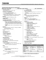
Page 13: ...Category Description dv3000 dv3500 Optical drive WLAN module 5 ...
Page 26: ...Computer major components 18 Chapter 3 Illustrated parts catalog ...
Page 129: ...Universal Serial Bus Pin Signal 1 5 VDC 2 Data 3 Data 4 Ground Universal Serial Bus 121 ...
Page 143: ......