background image

HP Omnibook XE3 (Technology Code GF) 

Removal and Replacement 

2-3 


Table 2-2. Required Equipment 

• 

#0 Phillips screwdriver, preferably magnetized. 

• 

Small flat-blade screwdriver. 

• 

5 mm hexagonal socket screwdriver. 

• 

Electrostatic device (wristband and pad). 


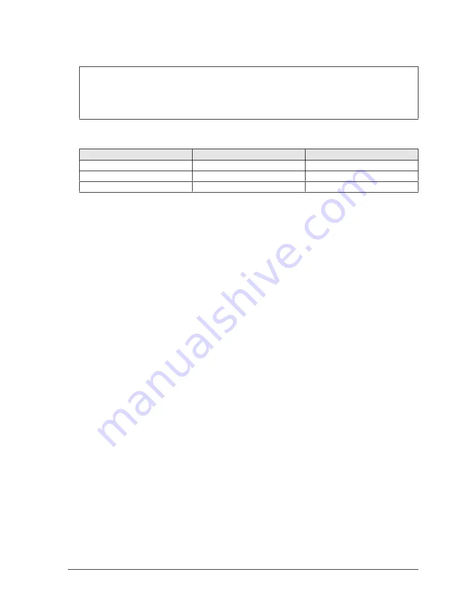
Table 2-3. Recommended Screw Torques 

Screw Thread Size 

Torque (cm-kgf) 

Torque (in-lbf) 

M2.5 (2–11 mm) 

3.0 – 3.5 

2.6 – 3.0 

M2.5 (12–19 mm) 

2.5 – 3.0 

2.2 – 2.6 

M3 3.0 

– 3.5 

2.6 – 3.0 


NOTES 

Summary of Contents for Omnibook XE3

Page 1: ... HP Omnibook XE3 Intel CPU Version Technology Code GF Service Manual ...

Page 2: ...Thank you for purchasing this Factory Service Manual CD DVD from servicemanuals4u com Please check out our eBay auctions for more great deals on Factory Service Manuals servicemanuals4u ...

Page 3: ... Co is also prohibited Portions of the programs that control this product may also be copyrighted by Microsoft Corporation Phoenix Technologies Ltd ESS S3 Incorporated Accton Trident Microsystems Incorporated Acer Laboratories Incorporated and Adobe Systems Incorporated See the individual programs for additional copyright notices This product incorporates copyright protection technology that is pr...

Page 4: ...ase HP Authorized Service Providers Only 2 19 Removing the CD Player PCA selected models HP Authorized Service Providers Only 2 21 Removing the Hinge Saddle Set HP Authorized Service Providers Only 2 22 Removing the Heatsink Assembly with Fan HP Authorized Service Providers Only 2 24 Removing the CPU Module HP Authorized Service Providers Only 2 26 Removing the Floppy Disk Drive HP Authorized Serv...

Page 5: ... 2 9 Removing the Hard Disk Drive 2 13 Figure 2 10 Removing the Hard Disk Carrier 2 13 Figure 2 11 Removing the Display 2 17 Figure 2 12 Motherboard DIP Switches 2 18 Figure 2 13 Removing the Top Case Retaining Screws 2 19 Figure 2 14 Removing the Top Case 2 20 Figure 2 15 Removing the CD Player PCA 2 21 Figure 2 16 Removing the Hinge Saddle Retaining Screws 2 22 Figure 2 17 Removing the Hinge Sad...

Page 6: ...ble 2 6 Replacing Small Parts User Replaceable 2 7 Table 2 7 Hard Disk Drive Replacement Part Numbers 2 12 Table 2 8 Motherboard Video DIP Switch Settings 2 18 Table 2 9 CPU Module Replacement Part Numbers 2 26 Table 2 10 Removing Notebook Components 2 38 Table 3 1 Scope of Diagnostic Tools 3 5 Table 3 2 Troubleshooting Suggestions 3 6 Table 3 3 e DiagTools Error Codes 3 26 Table 3 4 POST Terminal...

Page 7: ...mments HP Notebook Web Site http www hp com notebooks European mirror http www europe hp com notebooks HP Partnership Web http partner americas hp com Restricted to Authorized Resellers only HP Asia Pacific Channel Support Centre for DPSP Partners http www hp com au Restricted to DPSP Partners only HP MCD Web Site http www mcd hp com HP s internal web site for division information America Online K...

Page 8: ...58H 6 7 Celeron 933 MHz 14 1 in TFT XGA 20 GB 256 MB Yes Combo Modem LAN 9 Li Ion XP F3959H 6 7 Pentium III 933 MHz 14 1 in TFT XGA 20 GB 256 MB Yes Combo Modem LAN 9 Li Ion XP F3964H 6 7 Celeron 933 MHz 15 0 in TFT XGA 20 GB 256 MB Yes Combo Modem LAN 9 Li Ion XP F3960H 6 7 Pentium III 1 06 GHz 15 0 in TFT SXGA 30 GB 256 MB Yes Combo Modem LAN 9 Li Ion XP F4302HG 6 8 Celeron 933 MHz 14 1 in TFT X...

Page 9: ...P F3969H Pentium 933 MHz 14 1 in TFT XGA 20 GB 128 MB Yes DVD 8x Modem LAN 9 Li Ion 98 2K XP F3970H Pentium 933 MHz 14 1 in TFT XGA 20 GB 128 MB Yes CDRW Modem LAN 9 Li Ion 98 2K XP F3971H Pentium 933 MHz 14 1 in TFT XGA 20 GB 128 MB Yes Combo Modem LAN 9 Li Ion 98 2K XP F3972H Pentium 933 MHz 15 in TFT XGA 20 GB 128 MB Yes DVD 8x Modem LAN 9 Li Ion 98 2K XP F3973H Pentium 933 MHz 15 0 in TFT SXGA...

Page 10: ...y codes and the changes they signify for the products Before downloading software or drivers or performing repairs note the technology code for the HP notebook model Note that the first two characters of the BIOS ID for example GF M1 02 indicate the hardware technology You can also determine the BIOS ID using the BIOS Setup Utility or by pressing Esc during the boot process when the HP logo appear...

Page 11: ...2 Power switch 3 Status lights left to right power status battery status caps lock num lock scroll lock floppy drive access hard drive access CD DVD drive access See page 1 8 4 Pad Lock touch pad on off button 5 Touch pad pointing device 6 Scroll up down toggle 7 Click buttons 8 CD CD RW DVD or CD RW DVD drive 9 Built in microphone 10 CD DVD eject button 11 Standby button blue 12 Modem port select...

Page 12: ...to open computer Figure 1 3 Rear Left View 19 AC adapter jack 20 PS 2 port external mouse or keyboard 21 VGA port external monitor 22 Parallel port 23 IEEE 1394 port selected models 24 Infrared port selected models 25 TV output port 26 USB ports 27 Microphone jack 28 Kensington lock slot security connector 29 PC card slots upper and lower 30 System off switch for resetting notebook 31 PC card ejec...

Page 13: ...duct Information HP Omnibook XE3 Technology Code GF Figure 1 4 Bottom View 33 Battery 34 Battery latch 35 Primary RAM cover 36 Secondary RAM cover 37 Port replicator connector selected models 38 Mini PCI cover ...

Page 14: ...RAM Restarts quickly Restores network connections Press the blue standby button or Click Start Shut Down Standby Windows 98 or 2000 or Click Start Turn Off Computer Stand By Windows XP Press the blue standby button to return to your current session Instant On Hibernate mode Power status LED turns off Saves maximum power Saves the current session to disk then turns off Restores network connections ...

Page 15: ...e notebook s status lights located above the keyboard report power and battery status keyboard status and drive activity Figure 1 5 Status Lights 1 Power status 2 Battery status 3 Caps lock 4 Num lock 5 Scroll lock 6 Floppy disk drive activity 7 Hard disk drive activity 8 CD DVD drive activity ...

Page 16: ...C adapter is not connected or the adapter is connected but the battery is missing A Caps Lock Caps Lock is active 1 Num Lock Num Lock is active The Keypad Lock must also be on to use the embedded keypad Scroll Lock Scroll Lock is active Floppy disk drive activity Green the notebook is accessing the floppy disk drive Hard disk drive activity Green the notebook is accessing the hard disk drive CD DV...

Page 17: ...eases the display brightness Fn F2 Increases the display brightness Fn F5 Toggles among the built in display an external display and simultaneous display on both Fn F7 Mutes the notebook s speakers Fn F8 Toggles the built in numeric keypad on and off Does not affect an external keyboard If Num Lock is on the numeric functions are active otherwise cursor control is active Fn Lock key Toggles Scroll...

Page 18: ...s XP Press Ctrl Alt Del then click Shut Down Slide and hold the power switch for about five seconds until the display shuts down Insert a straightened paper clip into the system off switch on the left side of the notebook beneath the PC card eject buttons Figure 1 6 Resetting the Notebook After the notebook turns off press the blue standby button to restart it Note To boot from a CD or DVD insert ...

Page 19: ... control buttons also govern the volume for most other audio applications If the notebook is off or in standby or hibernate mode slide the multimedia power switch to the left to activate the player For details about using the CD DVD player see the notebook s Reference Guide Figure 1 7 Multimedia Buttons 1 Multimedia power use only when notebook is turned off or in standby or hibernate mode 2 Previ...

Page 20: ...aster Enhanced IDE 9 5 mm 2 5 in Supports Ultra DMA 33 66 100 Floppy disk drive 1 44 MB 12 7 mm 3 mode module Optical drive 24x CD 8x DVD 24x 8x CDRW 4x 24x 4x DVD CD RW Combo 12 7 mm module Display 13 3 14 1 15 0 in XGA 1024x768 or 15 0 in SXGA 1400x1050 TFT LCD Graphics Controller Intel 830M graphics controller 8 to 32 MB of video memory shared with main system memory and dynamically allocated b...

Page 21: ...4400 bps V 17 V 29 V 27ter and V 21 channel 2 Power management supports ACPI Power Management and wake up on Ring from S3 Input Output High speed bidirectional parallel port 25 pins EPP ECP capability VGA port 15 pins IEEE 1394 port on selected models Infrared port on selected models PS 2 6 pins for keyboard keypad or PS 2 mouse Y adapter compatible Microphone in headphone out jacks Internal micro...

Page 22: ... 2 5 A South Africa Replacement power cord 250 Vac 2 5 A Argentina Replacement power cord 250 Vac 2 5 A People s Republic of China Replacement power cord 250 Vac 2 5 A Chile Replacement power cord 250 Vac 2 5 A UK EPSR Hong Kong Singapore Replacement power cord 250 Vac 2 5 A India Adapters F1469A PS 2 Y adapter PC Cards F1625A 56 Kbps global modem v 90 PC Card for support only F1626A 10 100 LAN Ca...

Page 23: ... connections among the notebook s replaceable electronic modules In addition the table on page 1 16 lists the roles that the replaceable modules play in each of the notebook s functional subsystems Figure 1 8 Replaceable Module Diagram Motherboard PCA Mini PCI PCA CD ROM or DVD Drive SDRAM Modules Battery Keyboard PCMCIA Sockets 2 PCMCIA Cards Floppy Disk Drive Heatsink Assembly Top Case speakers ...

Page 24: ...ontroller video RAM Display output backlight power converter for backlight Hard disk Motherboard Hard disk drive Hard disk controller Hard disk mechanism Floppy drive Motherboard Floppy disk module I O controller floppy connector Floppy disk mechanism Keyboard Motherboard Keyboard Keyboard controller keyboard BIOS Key switches Touch pad Motherboard Top case Keyboard BIOS Touch pad sensor click but...

Page 25: ......

Page 26: ... 24 Keyboard page 2 10 Module CPU page 2 26 Module SDRAM page 2 5 PCA CD player page 2 21 PCA headphone page 2 39 PCA mini PCI page 2 6 PCA motherboard page 2 32 PCA switchboard page 2 39 Plate CPU support page 2 40 Saddle hinge set page 2 22 Socket PCMCIA page 2 40 Caution Always provide proper grounding when performing repairs Without proper grounding an electrostatic discharge can damage the no...

Page 27: ...ini PCI card Keyboard cover Keyboard Hard disk drive assembly Display assembly Top case assembly Hinge saddle set CD ROM DVD drive assembly Floppy disk drive assembly Headphone PCA Heatsink assembly with fan CPU module Motherboard or bottom case CD player PCA If removing only heatsink assembly or CPU module Only if not removing motherboard or bottom case Switchboard PCA also remove if removing mot...

Page 28: ...s screwdriver preferably magnetized Small flat blade screwdriver 5 mm hexagonal socket screwdriver Electrostatic device wristband and pad Table 2 3 Recommended Screw Torques Screw Thread Size Torque cm kgf Torque in lbf M2 5 2 11 mm 3 0 3 5 2 6 3 0 M2 5 12 19 mm 2 5 3 0 2 2 2 6 M3 3 0 3 5 2 6 3 0 NOTES ...

Page 29: ...ble Required Equipment None Removal Procedure Slide the battery s release latch then lift the battery out of its compartment Figure 2 2 Removing the Battery Reassembly Notes Insert the front rounded end of the battery into the battery compartment and lower the back end in until it clicks into place ...

Page 30: ...module through electrostatic discharge Required Equipment 0 Phillips screwdriver Removal Procedure 1 Unplug the AC adapter if present and remove the battery 2 On the bottom of the notebook loosen the screws holding the appropriate SDRAM cover the cover retains the screws and remove the cover Figure 2 3 Removing the SDRAM Covers 3 Press outward to release the latches at the sides of the SDRAM modul...

Page 31: ...ent and remove the battery 2 Loosen the screw holding the mini PCI cover the cover retains the screw and remove the cover 3 Press outward to release the latches at the sides of the PCA so that its free edge pops up 4 Disconnect the cable modem models only or cables modem LAN models only from the PCA 5 Gently pull the PCA out of its connector Figure 2 4 Removing the Mini PCI PCA Reassembly Notes Re...

Page 32: ...i PCI On the bottom of the notebook loosen the screw in the mini PCI cover the cover retains the screw and remove the cover Covers SDRAM On the bottom of the notebook loosen the screws in the SDRAM module covers the covers retains the screws and remove the covers Covers screw on display bezel Insert a small flat blade screwdriver under the cover and pry it loose To replace firmly press the adhesiv...

Page 33: ...rocedure 1 Unplug the AC adapter if present and remove the battery 2 Close the display and remove both screws from the backs of the hinge covers Figure 2 5 Removing the Keyboard Cover Retaining Screws 3 Open the notebook s display so that it lays flat 4 Use the flat blade screwdriver to carefully pry up the inside edges of the hinge covers until the cover pops loose then lift the cover off Screws ...

Page 34: ... the notch just to the right of the left display hinge Hold the cover by the hinge covers bow the center upwards slightly and snap it into place Note that the cover is held in place partly by tabs at the left and center of its bottom edge and at its upper left and right corners Make sure these tabs snap back into place when reinstalling the cover ...

Page 35: ...y 2 Remove the keyboard cover page 2 8 3 Loosen the four retaining screws along the top of the keyboard the keyboard retains the screws Figure 2 7 Loosening the Keyboard Retaining Screws 4 Raise the top of the keyboard then lift the keyboard up and out of the notebook Be careful not to pull on the ribbon cable connecting the keyboard to the notebook Caution Be careful not to touch the heatsink unt...

Page 36: ...nnect the ribbon cable from the motherboard Figure 2 8 Disconnecting the Keyboard Cable Reassembly Notes Lay the keyboard face down on the top case forward of its normal position then reconnect the ribbon cable Slip the metal tabs on the bottom of the keyboard into their slots in the top case then lower the keyboard into place Keyboard ribbon cable ...

Page 37: ...113 Drive hard disk 20 GB 9 5 mm IBM Diablo ATA100 F1660 60914 F1660 69114 Drive hard disk 30 GB 9 5 mm Toshiba ATA66 F2332 60903 F2332 69003 Required Equipment 0 Phillips screwdriver Removal Procedure 1 Unplug the AC adapter if present and remove the battery 2 Remove these additional assemblies Keyboard cover page 2 8 Keyboard page 2 10 Caution Be careful not to touch the heatsink until it has co...

Page 38: ...ement 2 13 Figure 2 9 Removing the Hard Disk Drive 5 Loosen all four screws in the underside of the hard drive carrier the carrier retains the screws then slide the drive back and up out of the case Figure 2 10 Removing the Hard Disk Carrier Pin connector ...

Page 39: ...ide so that the connector slides off evenly without bending the connector pins Reassembly Notes Carefully put the pin connector back onto the pins on the end of the new hard drive Work at each end alternately so that the connector slides on evenly without bending the connector pins Be careful not to trap the heatsink and keyboard cables beneath the hard drive ...

Page 40: ... erases all data on the drive After formatting you must reinstall any applications Do not interrupt the following process or unplug the AC adapter until the process is complete 1 Back up all data from the hard disk 2 Connect the AC adapter to the notebook 3 Insert Recovery CD disk 1 into the notebook s CD DVD drive 4 Turn on or restart the computer 5 When the HP logo appears press Esc to display t...

Page 41: ...e 2 8 Keyboard page 2 10 3 Remove both screws from the switchboard PCA and carefully lift the PCA off the connector underneath it Notice the retaining hook at the right end of the PCA Be carefully not to pull on the cable attached to the PCA 4 Disconnect the cable from the switchboard PCA and remove the PCA from the notebook 5 Remove the four flanged screws from the display hinges This may be easi...

Page 42: ...ews support the display so that it remains approximately flat Before installing the switchboard PCA make sure the large display cable lies within the notch in the hinge saddle When installing a new display assembly follow the procedure given in Installing a New Display Assembly on the following page Screws M2 5x4 mm 2 Screws flanged M2 5x8 mm 4 ...

Page 43: ...nufacturer and model in the table below and set the DIP switches on the motherboard as shown Table 2 8 Motherboard Video DIP Switch Settings Model 1 2 3 4 Hitachi 15 in TFT SXGA ON OFF OFF OFF Hitachi 15 in TFT XGA OFF ON OFF OFF UNIPAC 13 3 in TFT XGA OFF OFF ON OFF CPT 14 1 in TFT XGA ON OFF ON OFF LG 15 in TFT XGA ON ON ON OFF UNIPAC 14 1 in TFT XGA OFF OFF OFF ON LG 13 3 in TFT XGA ON OFF OFF ...

Page 44: ...the eight retaining screws from the bottom case Figure 2 13 Removing the Top Case Retaining Screws 4 Disconnect the touch pad cable and speaker cable from the motherboard 5 Remove the six retaining screws from the top case 6 Raise the back of the top case then gradually loosen the case moving toward the front of the notebook the right rear corner may require extra care to work free 7 Carefully lif...

Page 45: ...herboard Figure 2 14 Removing the Top Case Reassembly Notes Make sure the touch pad cable and speaker cable connectors are fully inserted squarely in their sockets Make sure the tabs along the edges of the case snap shut Screws M2 5x4 mm 5 Screw M2 5x8 mm 1 Speaker cables Touch pad cable CD player ribbon cable ...

Page 46: ...driver Removal Procedure 1 Unplug the AC adapter if present and remove the battery 2 Remove these additional assemblies Keyboard cover page 2 8 Keyboard page 2 10 Display assembly page 2 16 Top case page 2 19 3 Remove both standoff screws use a 5 mm socket screwdriver and lift the PCA out of the top case Figure 2 15 Removing the CD Player PCA CD player PCA standoff screws 5 mm 2 ...

Page 47: ...ge 2 8 Keyboard page 2 10 Display assembly page 2 16 Top case page 2 19 3 Remove the two retaining screws from the bottom case Figure 2 16 Removing the Hinge Saddle Retaining Screws 4 Remove the retaining screws from the back of the notebook just below the display hinges 5 Remove both retaining screws from the hinge saddle set 6 Lift the hinge saddle set out of the notebook You may need to free th...

Page 48: ...the Hinge Saddle Reassembly Notes Make sure the posts on the underside of the hinge saddle line up with the hinge support openings in the bottom case and that the holes in the front ends of the saddle fit over the alignment posts in the bottom case Screws M2 5x8 mm 2 Screws M2 5x8 mm 2 ...

Page 49: ...emoval Procedure 1 Unplug the AC adapter if present and remove the battery 2 Remove these additional assemblies Keyboard cover page 2 8 Keyboard page 2 10 Display assembly page 2 16 Top case page 2 19 Hinge saddle set page 2 22 3 Disconnect the fan cable from the motherboard 4 Remove all four retaining screws their springs are attached to them 5 Lift the heatsink out of the notebook ...

Page 50: ...acement 2 25 Figure 2 18 Removing the Heatsink Assembly Reassembly Notes Make sure the fan cable is not pinned under the assembly Make sure the thermal pad on the heatsink is not damaged and replace if necessary Heatsink retaining screws with springs 4 ...

Page 51: ...alatin F3946 60901 F3946 69101 Required Equipment 0 Phillips screwdriver Small flat blade screwdriver Removal Procedure Caution Be careful not to touch the upper surface of the CPU module Handle it only by its edges or you could damage it 1 Unplug the AC adapter if present and remove the battery 2 Remove these additional assemblies Keyboard cover page 2 8 Keyboard page 2 10 Display assembly page 2...

Page 52: ...HP Omnibook XE3 Technology Code GF Removal and Replacement 2 27 Figure 2 19 Removing the CPU Module Pentium CPU module CPU module lock mechanism ...

Page 53: ...hat none of its pins are bent or otherwise damaged Pentium SKUs Carefully insert the tip of the flat blade screwdriver in the CPU module lock mechanism and turn the screwdriver a few degrees clockwise until the mechanism clicks into its LOCK position The CPU socket moves slightly to the right when this happens Celeron SKUs Carefully insert the CPU module into the motherboard The module is keyed fo...

Page 54: ...lips screwdriver Removal Procedure 1 Unplug the AC adapter if present and remove the battery Keyboard cover page 2 8 Keyboard page 2 10 Display assembly page 2 16 Top case page 2 19 Hinge saddle set page 2 22 2 Release the drive s ribbon cable from its connector on the motherboard 3 Remove the two retaining screws 4 Lift the floppy drive out of the notebook ...

Page 55: ...val and Replacement HP Omnibook XE3 Technology Code GF Figure 2 21 Removing the Floppy Disk Drive Reassembly Notes Make sure the headphone PCA cable is not trapped under the floppy disk drive Screws M2 5x4 mm 2 ...

Page 56: ...ent and remove the battery Keyboard cover page 2 8 Keyboard page 2 10 Hard disk drive page 2 12 Display assembly page 2 16 Top case page 2 19 Hinge saddle set page 2 22 2 Pull the drive to the right off of its connector and out of the notebook Figure 2 22 Removing the CD DVD Drive Reassembly Notes Place the drive so that its connector aligns with that on the motherboard then gently press it to the...

Page 57: ...ically store the motherboard s serial number and service ID for transfer to the new motherboard 1 Exit Windows and boot to a DOS prompt For Windows 98 press F8 during reboot and select Command Prompt Only For Windows 2000 or XP boot from a DOS boot floppy disk 2 Run ESN EXE from one of these sources On a factory software installation change to hp drivers hputils and type esn at the prompt or Copy ...

Page 58: ...le page 2 26 Floppy disk drive page 2 29 CD DVD drive page 2 31 3 Remove all four standoff screws from the back of the notebook 4 Remove both retaining screws from the motherboard 5 Disconnect the cable modem models only or cables modem LAN models only at the right rear corner of the motherboard 6 Disconnect the cable from the headphone PCA 7 Remove the CPU standoffs 8 Remove the CD DVD drive supp...

Page 59: ...sembly Procedure When reinstalling the motherboard see Reinstalling the Motherboard on page 2 35 When reinstalling the bottom case see Replacing the Bottom Case on page 2 36 Screw M2 5x5 mm 1 Screw M2 5x5 mm 1 Standoff screws 5 mm 4 CPU standoff screws 5 mm 2 Headphone PCA CPU support plate CD DVD support ...

Page 60: ...ter installing a new motherboard you must electronically transfer to it the serial number and service ID from the previous motherboard and set the video DIP switches for the notebook s display type 1 Exit Windows and boot to a DOS prompt For Windows 98 or ME press F8 during reboot and select Command Prompt Only For Windows 2000 or XP boot from a DOS boot floppy disk 2 Run ESN EXE from the same sou...

Page 61: ... Procedure 1 Install a new Microsoft Product ID label 2 Transfer the old serial number label and install a new overlay or create a new serial number label using the steps below 3 If you need to install or replace the docking or PCMCIA doors refer to the figures below Figure 2 24 Installing Docking Doors ...

Page 62: ...r warranty period and manufacturing location 1 Open a new document based on the serial label template 2 Enter the information from the old serial label and print the new label on plain white paper The new label does not have barcodes 3 Carefully cut out the new serial label just inside the border and place it into the inner recess in the bottom case The bottom of the label goes toward the front of...

Page 63: ...iven in the table below Table 2 10 Removing Notebook Components Component Removal Procedure Additional Steps Case bottom See page 2 32 Case top See page 2 19 Cover keyboard See page 2 8 CPU module See page 2 26 Display assembly See page 2 16 Doors docking Mini PCI PCA page 2 6 Keyboard cover page 2 8 Keyboard page 2 10 Hard disk drive page 2 12 Display assembly page 2 16 Top case page 2 19 Hinge s...

Page 64: ...Heatsink with fan See page 2 24 Keyboard See page 2 10 PCA CD player See page 2 21 PCA headphone Keyboard cover page 2 8 Keyboard page 2 10 Display assembly page 2 16 Top case page 2 19 Hinge saddle set page 2 22 Remove the retaining screw from the PCA disconnect the cable to the motherboard and lift the PCA out of the notebook You can lift the floppy drive slightly for access PCA motherboard See ...

Page 65: ...ge 2 16 Top case page 2 19 Hinge saddle set page 2 22 Heatsink assembly page 2 24 CPU module page 2 26 Floppy disk drive page 2 29 CD DVD drive page 2 31 Motherboard page 2 32 Saddle hinge set See page 2 22 Socket PCMCIA Keyboard cover page 2 8 Keyboard page 2 10 Display assembly page 2 16 Top case page 2 19 Hinge saddle set page 2 22 Remove the four screws attaching the PCMCIA socket to the mothe...

Page 66: ...book and for identifying faulty modules Troubleshooting information Checking for customer abuse page 3 3 Troubleshooting the problem page 3 4 Verifying the repair page 3 4 Suggestions for troubleshooting page 3 5 Diagnostic tools e DiagTools diagnostic program page 3 23 Power on self test page 3 29 Sycard PCCtest 450 PC Card page 3 32 Desktop Windows Management Interface page 3 33 BIOS Setup utili...

Page 67: ...ty repair follow the basic troubleshooting steps shown below Check the customer s description of the problem and any supporting information Try to duplicate the customer s problem Troubleshoot the problem using Diagnostic tools Troubleshooting suggestions Verify the repair by testing the functionality of the complete unit Check for customer abuse Figure 3 1 Basic Troubleshooting Steps ...

Page 68: ...use cannot be declared If the damage could have a cause other than customer abuse customer abuse cannot be declared If the unit shows any of the following customer abuse is declared Missing parts Broken plastic parts Parts not original to the unit Damaged or missing keys on the keyboard Table 3 2 on page 3 6 includes additional criteria for determining customer abuse to specific parts of the unit ...

Page 69: ...d the Sycard PCCtest Table 3 1 on page 3 5 shows how you can use these tools to isolate the cause of the notebook s problem The troubleshooting suggestions on page 3 6 include general suggestions for repairing units that show specific failure symptoms Swapping modules that may be defective with others known to be good is generally an ideal way to find the component responsible for the problem A fa...

Page 70: ...ests Describes Pointer Tests Misc menu Describes Configures Audio Tests System Misc menus Parallel Tests Misc menu Describes LAN Describes Modem Tests User menu Infrared Describes Configures PS 2 port Tests KBD Misc menus USB Tests USB menu Describes Docking port Tests System menu using docks PCMCIA Tests Misc menu Tests Describes Win 98 only AC adapter Status Docking products Tests ports and inte...

Page 71: ...light does not turn on replace motherboard If power status light turns on but display remains off try external monitor If monitor shows successful boot replace display assembly If monitor shows activity but BIOS does not complete replace display assembly If monitor is blank replace switchboard PCA replace motherboard If power status light and display turn on and BIOS completes but OS does not star...

Page 72: ...certain sites See page 5 1 Power Battery No power Make sure charged battery is installed or AC adapter connected Try another battery or AC adapter if available AC adapter Battery Motherboard Does not run on battery empty battery indication Check battery and contacts Try another battery if available Battery or contacts Motherboard Beeps repeatedly Notebook beeps repeatedly when battery is low Conne...

Page 73: ...ptimum speed for movies use Power Options or Power Management in Control Panel to select Portable Laptop power scheme When using applications with automatic save feature such as MS Word extend save time or disable to reduce hard disk access and power usage PCMCIA card use can affect battery life Some PCMCIA cards draw power even while not in use Heavy modem use can affect battery operating time Ba...

Page 74: ... or undocked while going on standby or resuming Make sure notebook has completely finished going on standby or completely resumed before docking or undocking Does not suspend to Standby mode as expected The computer won t suspend if it has an active connection to another computer If the computer is busy it normally waits to finish the current operation before suspending Does not automatically ente...

Page 75: ...nection Display assembly Check the display cable connection See quality statement on page 5 2 Punctured display Declared to be caused by customer abuse Vertical crack near center of display Usually caused by closing display with pencil sized object on keyboard Declared to be caused by customer abuse Scratched display glass Declared to be caused by customer abuse Local area of dark or light discolo...

Page 76: ...e Hard disk makes buzzing or whining noise Back up drive immediately Check hard drive installation Check for alternate noise sources such as PCMCIA drive or fan Depends on source of noise Files are corrupted Run virus scan program Check disk surface using ScanDisk Windows 98 or Tools tab in disk s Properties sheet Windows 2000 or XP Back up files if possible then use Recovery CDs to reformat hard ...

Page 77: ...serted properly CD DVD drive DVD movie stops playing DVD may be double sided Movie may be paused Press Play button Region Code error DVDs contain embedded regional codes that prevent them from playing outside the region in which they are sold This error occurs when trying to play DVD intended for different region Important most DVD drives allow the region code to be changed only a limited number o...

Page 78: ...reduce color depth or display resolution All DVD play is erratic Some DVDs include software called PC Friendly This software can cause errors or erratic play If needed uninstall PC Friendly and restart notebook Keyboard Some or all keys do not work properly Try reinserting ribbon cable in connector on motherboard Keyboard Motherboard External keyboard does not work Check connections External keybo...

Page 79: ...M module Memory doesn t increase after adding RAM Make sure SDRAM modules are installed properly SDRAM module Audio No sound is audible Increase sound volume Make sure sound is enabled software controls Check for sound resource conflicts in Device Manager Sound may not operate properly in MS DOS mode Check speaker cable connection Top case Motherboard Check operation using headphones or external s...

Page 80: ...rify that host modem supports 56K V 90 connection speed Try connecting later in case line quality or other external factor is cause of problem Modem will not connect at any speed Make sure notebook s modem is properly connected to wall telephone jack Check cables Verify settings in Control Panel Make sure parity speed word length and stop bits match on sending and receiving modems Restart notebook...

Page 81: ... dials incorrectly Check number you entered including digits required for outside access or long distance Check dialing options in Control Panel look for duplicate digits for outside access or long distance In foreign country modem may not recognize dial tone In Control Panel disable option that waits for dial tone Disable call waiting Modem seems slow Check for excess line noise or static often d...

Page 82: ...line not PBX or digital line In a hotel ask for data line General problems If PC card modem is not working disable internal modem in Control Panel Download latest modem driver from technical support area of HP Notebook web site see page vi Mini PCI PCA Motherboard One Touch button problems Buttons not working properly Make sure correct applications are associated with buttons in One Touch tab of K...

Page 83: ...king troubleshooter in Windows Help Make sure LAN cable is Category 3 4 or 5 for 10Base T operation or Category 5 for 100Base TX operation Maximum cable length is 100 m 330 ft Motherboard Can t browse Network Neighborhood or My Network Places Check with network administrator to make sure network supports NetBEUI protocol Use Windows Search to locate computer on network Can t log in to Netware serv...

Page 84: ... IrDA Fast Infrared Port On Advanced tab click Infrared Transceiver A in Property window then select IBM 31T1100 from pull down menu Make sure the line between the two infrared ports is not blocked ports face each other squarely and are no more than 1 meter apart Sunlight heat from nearby equipment or other sources of infrared radiation can cause transmission errors Make sure only one application ...

Page 85: ...sing a flashlight look for bent pins inside PCMCIA socket If both slots have problems replace motherboard If only one slot has a problem try replacing PCMCIA socket PC card modem not working Disable internal modem Video file playback AVI or MPEG file doesn t play with two displays Before playing press Fn F5 to switch to one display Cannot switch displays after play begins If using both displays vi...

Page 86: ... Del to see if an application is not responding Restart notebook If hard disk has spun down to conserve power it can take several seconds to spin up If needed use Power Management or Power Options in Control Panels to change hard disk time out to match standby time out Some file browsers respond slowly while processing graphics or waiting for broken network connections to time out Check for overhe...

Page 87: ...by button to turn notebook back on Port replicator Docking product I O problems Make sure AC power is connected to port replicator Make sure notebook is fully inserted in port replicator Check notebook s power supply Try using corresponding port on notebook while undocked Port replicator Motherboard Test corresponding notebook ports while undocked Port replicator is not repairable and must be exch...

Page 88: ...s hardware diagnostic program provides two levels of testing Basic user level hardware test Advanced individual hardware tests Figure 3 2 e DiagTools Screens Basic and Advanced The tests are designed to run after the system restarts so that the notebook will be in a predictable state during the tests The tests are non destructive and are intended to preserve the state of the notebook The notebook ...

Page 89: ... without running the advanced tests press F4 to view the Support Ticket Press F3 to exit 9 Optional Run the advanced tests Press F2 to open the advanced test screen 10 Select and run the appropriate tests Note that individual tests do not appear if the hardware they test is not detected Press the following keys to run tests Enter Runs the highlighted test F5 or Space Marks unmarks the highlighted ...

Page 90: ... View to display the Support Ticket 17 To add information about the problem click Comments and type the information then click OK To save or print the Support Ticket click Save As or Print Note that the parallel port test is more thorough if you connect a loop back connector to the port before running the test for that port See the wiring diagram below 14 1 25 13 Figure 3 3 Parallel Loopback Conne...

Page 91: ...IOS Setup and check the hard disk type Check the hard disk connection Replace the hard disk Replace the motherboard 0208h 0209h Repeat the test Code Suggestions 020Ah 0211h Repeat the test Run Windows disk checking tools Replace the hard disk 0220h Replace the motherboard 0240h Replace the hard disk Replace the motherboard 0252h 0254h Repeat the test Replace the hard disk 025Ah 0260h Repeat the te...

Page 92: ...lace the motherboard If error also occurs with external monitor replace the motherboard 9016h Reset the notebook Replace the motherboard 9017h See Error Bookmark not defined for cosmetic guidelines If warranted replace the display assembly Code Suggestions CD Tests 0A00h Insert a CD in the drive 0A01h Repeat the test Replace the CD drive 0A02h No repair Automatic close not supported 0A03h Insert a...

Page 93: ...Restart the reflector unit Replace the motherboard Sound Tests 9018h 901Ah If this error occurs for external headphone replace the motherboard Otherwise check speaker connections Replace the top case Code Suggestions Dock Tests 9071h 9073h Update the notebook BIOS Replace the dock s electronics PCA 9075h 9077h 907Ah Replace the dock s electronics PCA 907Bh Replace LED button assembly in dock 907Eh...

Page 94: ... or unusual AC adapter configuration 3 Press the system off switch to return the notebook to a known state If the BIOS detects a terminal error condition it halts POST after issuing a terminal error beep code see the following table The beep code indicates the POST routine in which the terminal error occurred Table 3 4 POST Terminal Error Beep Codes Beep Codes POST Description 1 One short beep bef...

Page 95: ...ues If you do not want these values enter BIOS Setup and enter your own values If the error persists check the system battery Connect the AC adapter for at least 24 hours Replace the motherboard 0260 System timer error The timer test failed Replace the motherboard 0270 Real time clock error The real time clock failed the BIOS test The motherboard may need to be replaced 0280 Previous boot incomple...

Page 96: ...he amount in KB of system RAM successfully tested Operating system not found No operating system was found on drive A or drive C Enter BIOS Setup and see if the hard disk and drive A are properly identified Parity Check 1 nnnn A parity error was found in the system bus Parity is a method for checking errors in binary data a parity error indicates that some data has been corrupted The BIOS attempts...

Page 97: ...n 1 05 PC Card PCCtest 450 460 test software disk Software updates are available at the Sycard Technology web site http www sycard com Configuration headers PC Card 16 bit and CardBus 32 bit that attach to the card In addition you will need this CardBus extender card such as the Sycard PCCextend 70 to avoid wear on the Sycard PCMCIA connector The Sycard PCCtest 450 and 460 provide the following te...

Page 98: ...http www hp com toptools the contents are the same in both cases The package must be properly installed before it can be used Install the package as follows To install the DMI preloaded on the hard disk In Windows click Start Programs or All Programs HP TopTools for Notebooks Setup To install the DMI from the Recovery CDs or from floppy disks 1 Insert Recovery CD disk 1 into the CD DVD drive or in...

Page 99: ... Setup If the settings cause a conflict between devices during reboot the system prompts you to run BIOS Setup again and marks the conflicting settings Table 3 7 BIOS Setup Menus and Parameters Omnibook XE3 Introduced with BIOS version GF M1 01 Windows XP or GF M1 02 Windows 98 and 2000 Autumn 2000 Main Menu Description Default BIOS Revision Shows the current BIOS version Detected automatically UU...

Page 100: ...ord is Shows if an administrator password is set Clear Set User Password Sets changes or clears the user password The administrator password must be set first The password can have no more than 8 characters 0 9 A Z and cannot include special or accented characters Set Administrator Password Sets changes or clears the administrator password which protects BIOS Setup settings The password can have n...

Page 101: ...Undock the notebook if it is docked and remove any PC cards from it 3 Connect the AC adapter to the notebook 4 Connect any cables or equipment needed to connect to the Internet 5 Click Start Programs or All Programs HP e DiagTools e DiagTools for Windows 6 Click Update select Download New and click OK Follow the instructions that appear Once the update process begins do not interrupt it The first ...

Page 102: ...de GF Replaceable Parts 4 1 4 Replaceable Parts This chapter contains an exploded view of the notebook and the following lists of parts Replaceable parts page 4 3 Accessory replaceable parts page 4 5 Part number reference page 4 6 ...

Page 103: ...4 2 Replaceable Parts HP Omnibook XE3 Technology Code GF Figure 4 1 Exploded View ...

Page 104: ...o 6 Drive DVD CD RW Combo F3925 60939 No 6 Drive DVD F3925 60938 No 7 Drive floppy disk F3925 60935 No 8 Drive hard disk 10 GB 9 5 mm Hitachi F1664 60902 F1664 69002 No 8 Drive hard disk 10 GB 9 5 mm Hitachi F2072 60908 F2072 69108 No 8 Drive hard disk 10 GB 9 5 mm IBM DJSA 210 F1660 60912 F1660 69112 No 8 Drive hard disk 20 GB 9 5 mm Hitachi F2072 60913 F2072 69113 No 8 Drive hard disk 20 GB 9 5 ...

Page 105: ...ondary see above kit No 17 Kit hard disk drive carrier includes bracket strap connector mounting screws F2111 60956 No Kit LCD screw covers includes covers for all display sizes F3925 60975 Yes Kit screws includes all screws needed to replace all notebook FRUs F3925 60976 No 18 Screw M2 5x4 mm see above kit No 19 Screw M2 5x5 mm see above kit No 20 Screw M2 5x8 mm see above kit No 21 Standoff scre...

Page 106: ...hange User Part Number Repl 3Com Bluetooth PC Card F2196 80001 Yes AC adapter Ultraslim 60W 19V output 0950 3988 Yes AC adapter Ultraslim 60W 19V output 0950 4207 Yes Adapter auto 72W Europe Only F2297 80001 Yes Horn PS 2 US Keyboard F2291 60902 Yes Module SDRAM 128 MB PC133 SODIMM 1818 8504 Yes Module SDRAM 256 MB PC133 SODIMM 1818 8635 Yes Polk AMR 50 Speakers F2291 60903 Yes Power cord replacem...

Page 107: ...cement Chile Yes 8120 8699 Power cord replacement Hong Kong Singapore U K Yes 8121 0702 Power cord replacement India Yes F1660 60912 F1660 69112 Drive hard disk 10 GB 9 5 mm IBM DJSA 210 No F1660 60914 F1660 69114 Drive hard disk 20 GB 9 5 mm IBM Diablo ATA100 No F1664 60902 F1664 69002 Drive hard disk 10 GB 9 5 mm Hitachi No F2072 60908 F2072 69108 Drive hard disk 10 GB 9 5 mm Hitachi No F2072 60...

Page 108: ...80001 Adapter auto 72W Europe Only Yes F2300 60902 Keyboard Iceland No F2332 60903 F2332 69003 Drive hard disk 30 GB 9 5 mm Toshiba ATA66 No F3257 60904 F3257 69004 Module CPU Pentium III 933 MHz Tualatin No F3257 60906 F3257 69006 Module CPU Pentium III 1 13 GHz Tualatin No F3377 60950 PCA mini PCI modem Yes F3925 60901 Battery LiIon 9 cell Yes F3925 60902 Battery LiIon 6 cell Yes F3925 60903 Bat...

Page 109: ...n English Windows XP Home Edition mfg p n F3940 12005 No F3941 60901 F3941 69101 Module CPU Pentium IIIM 1 06 GHz Tualatin No F3943 60901 F3943 69101 Module CPU Celeron T 800 MHz Tualatin No F3944 60901 F3944 69101 Module CPU Celeron T 866 MHz Tualatin No F3944 60901 Recovery CDs N American English Windows XP Home Edition mfg p n F3944 12001 No F3944 60902 Recovery CDs International English Window...

Page 110: ...s XP Professional Edition mfg p n F3944 12016 No F3944 60917 Recovery CDs Spanish Windows XP Professional Edition mfg p n F3944 12017 No F3944 60918 Recovery CDs Swedish Windows XP Professional Edition mfg p n F3944 12018 No F3944 60919 Recovery CDs Japanese Windows XP Professional Edition mfg p n F3944 12019 No F3944 60920 Recovery CDs Finnish English Windows XP Professional Edition mfg p n F3944...

Page 111: ......

Page 112: ...actual and current owner This requires a sales receipt showing the notebook serial number and owner s name or a written statement from the owner attesting that he or she is the owner of the notebook The statement can be a fax copy of the document The fact that the notebook is in the hands of an HP representative on behalf of the customer is not evidence of ownership In addition HP will not remove ...

Page 113: ...termine whether the display should be considered for replacement These are the only conditions in this guideline that may call for a replacement due to a defect in material or workmanship based on the HP Limited Warranty Statement 3 If a display is considered for replacement make sure the customer understands that cosmetic variations may also exist on the replacement display and may require the cu...

Page 114: ...nce of multiple defective dots within 15 mm Mechanical Imperfections Discoloration Polarizer bubbles dents b scratches Any polarizer bubble discoloration or dent that is visible from at least 36 cm 14 in Definitions of imperfections a A bright or dark dot is a subpixel red green or blue dot that is stuck on or off b A polarizer dent or bubble is a light spot with a darker border that appears on a ...

Page 115: ......

Page 116: ......

Page 117: ...1 Product Information 2 Removal and Replacement 3 Troubleshooting and Diagnostics 4 Replaceable Parts 5 Reference Information QJOLVK 3ULQWHG LQ 7DLZDQ 3DUW 1XPEHU 3 ...

Reviews: