background image

HP Kayak XU 03xx PC Workstation   — Installing Accessories In Your HP PC Workstation

Installing a Processor

28

English

Installing a Processor

Some operating systems support a second processor for enhanced 
performance. Contact your authorized reseller for up-to-date 
information.

NOTE 

The 

Setup

 program provides an option to disable the second processor.

1

Disconnect the computer’s power cord and any LAN or 
telecommunications cable.

2

Remove the computer’s cover (refer to page 3).

3

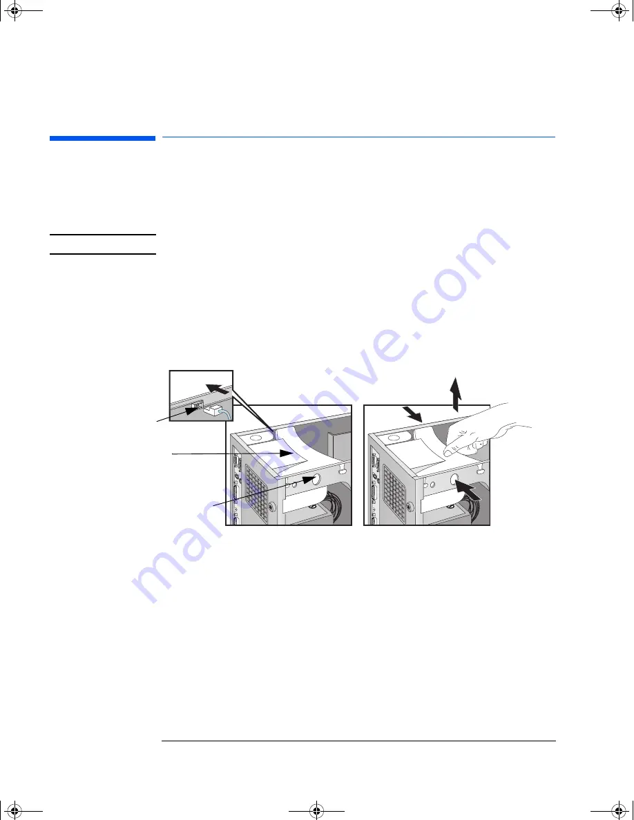
Press the retaining buttons on each side of the HP UltraFlow airflow 
guide and lift it partly out of the PC Workstation’s case.

4

Remove the fan connection to the system board and lift the airflow 
guide completely out of the PC Workstation’s case.

5

Slide out the power supply to improve access to the processor 
sockets refer to page 6

,

 and carefully place the PC Workstation on 

its side.

6

Remove the transparent airflow guide covering the processor 
sockets.

HP UltraFlow 
Airflow Guide

Retaining button

Fan connection to 
system board

03xx-i~1.fm  Page 28  Tuesday, February 16, 1999  10:15 AM

Summary of Contents for Kayak XU 03xx

Page 1: ...orkstation Installing Accessories In Your HP PC Workstation Explains in detail how to install accessories such as extra memory accessory boards and additional disk drives 03xx i 1 fm Page 1 Tuesday February 16 1999 10 15 AM ...

Page 2: ...CI slots one used by SCSI LAN board one with RAIDport One combination PCI or ISA slot One 16 bit ISA slot Front Access Drives for example 3 5 inch 1 44 MB flexible disk drive one third height 5 25 inch 1 2 MB flexible disk drive half height 5 25 inch tape drive half height Internal Mass Storage Devices 5 Pairs of Rails for Front Access Devices 3 5 inch disk drive rails 5 25 inch disk drive rails M...

Page 3: ...unications network Always replace the cover on the PC Workstation before switching it on again Removing the Cover 1 Switch off the display and computer 2 Disconnect all power cables and any telecommunications cables 3 If necessary unlock the cover using the key on the back panel 4 Lift the two latches on the front sides of the computer upwards 5 Grasp the cover on the sides at the back of the comp...

Page 4: ... sides of the cover are lifted up and that the lock is unlocked 3 Slide the cover onto the computer making sure that the two guides at the bottom of the case slide into the two rails at the base of the computer Firmly slide the cover backwards into position 4 Lower the latches on the front sides of the cover 5 If required lock the cover using the key provided 6 Reconnect all the power cables Press...

Page 5: ...he Hardware Control Panel It is designed to detect whether your PC Workstation has been opened since the last time it was used If your PC Workstation has been opened it is assumed that the system configuration has changed and a full start up check is carried out If your PC Workstation has not been opened it is assumed that the system configuration has not changed and a reduced start up check is ca...

Page 6: ...e retaining buttons on each side of the HP UltraFlow airflow guide and lift it partly out of the PC Workstation s case 4 Remove the fan connection to the system board and lift the airflow guide completely out of PC Workstation s case 5 Unscrew the four self retaining screws at the back of the power supply HP UltraFlow Airflow Guide Retaining button Fan connection to system board Unscrew the self r...

Page 7: ...power supply unit remains connected to the computer Replacing the Power Supply after Installing Accessories 1 Check that all internal cables are safely routed 2 Slide the power supply back into the computer 3 Tighten the four self retaining screws 4 Replace the HP UltraFlow airflow guide 5 Reconnect the fan to the system board Slide the power supply unit clear of the computer Power Supply 03xx i 1...

Page 8: ...y rest the accessory bag on top of the power supply while you are removing the accessory from the bag Handle the accessory as little as possible and with care To install a main memory module 1 Disconnect the computer s power cord and any LAN or telecommunications cable 2 Remove the computer s cover refer to page 3 3 Press the retaining buttons on each side of the HP UltraFlow airflow guide and lif...

Page 9: ...nnector until the retaining clips click into position Repeat this procedure for each additional memory module you want to install 11 Install any other accessories if necessary then replace all units and reconnect all cables and power cords Replace the cover refer to page 4 12 Check the HP Summary Screen to verify the new configuration Slide the memory module into the slot at 90o to the system boar...

Page 10: ...ttle as possible and with care To install a video memory module 1 Switch off the display and computer and disconnect the power supply cables and any telecommunications cables Remove the computer s cover refer to page 3 and carefully place the PC Workstation on its side 2 Carefully remove the board from the accessory slot holding the board at each end by its top edge Do not bend the board With its ...

Page 11: ...you need to use a special video driver for your application you may be asked to insert the CD ROM or diskette containing the driver Video Adapter Accessories Available from Other Sources Additional accessories including memory upgrades and a video MPEG module are available for your video adapter However these accessories cannot be ordered from HP Contact your dealer for more details about these ac...

Page 12: ...e front access drive shelves for front access drives and hard disk drives Your computer is supplied with one 3 5 inch flexible disk drive and a CD ROM drive If your computer is supplied with a hard disk the hard disk will be installed in the second internal shelf Two internal shelves for 3 5 inch disks Two shelves for 3 5 inch drives Three shelves for 5 25 inch drives 03xx i 1 fm Page 12 Tuesday F...

Page 13: ...aNarrow 8 bit SCSI with two connectors A flexible disk drive cable with a single connector This supports a flexible disk drive the connector is attached to the flexible disk drive supplied An Ultra ATA 33 IDE cable that supports two fast IDE devices If you install a CD ROM drive CD RW drive a Zip drive or a third hard disk drive connect it to this cable 16 bit SCSI with five 68 pin SCSI connectors...

Page 14: ...ntegrated Ultra ATA 33 IDE controller The Ultra ATA 33 IDE controller on the PCI bus supports up to two fast 33 MB per second IDE devices The Ultra wide 16 bit SCSI controller is dedicated to hard disk drives and supports up to five internal SCSI devices The Ultra SCSI 16 bit interface board installed in a PCI slot supports up to 13 external 16 bit SCSI devices and automatically switches to non Ul...

Page 15: ... installation procedure to follow Before Installing a SCSI Hard Disk If you are installing an additional SCSI drive you should assign an unused SCSI address to this accessory SCSI addresses range from 0 to 7 for Ultra narrow 8 bit SCSI and from 0 to 15 for Ultra wide 16 bit SCSI SCSI address 0 is used by the first SCSI hard disk drive and SCSI address 7 is reserved for the integrated SCSI controll...

Page 16: ...e 3 3 Remove the fan connection to the system board refer to the illustration on page 6 4 Press the retaining buttons on each side of the HP UltraFlow airflow guide and lift it out of the PC Workstation s case 5 Slide the power supply out to improve access to the internal shelf refer to page 6 6 Slide the drive into position in the first internal shelf and align the screw holes in the drive with t...

Page 17: ... be connected to a free IDE connector on the IDE cable you can add up to two IDE devices Wide SCSI devices should be connected to a free SCSI connector on the SCSI cable you can add up to five SCSI devices Narrow SCSI devices should be connected to a free SCSI connector on the SCSI cable you can add up to two SCSI devices Up to 13 external SCSI devices can be connected via the external SCSI connec...

Page 18: ...cooled you should only install drives that are up to one inch 1 in height and of a speed equal to or less than 7200 rpm in this shelf 1 Disconnect the computer s power cord and any telecommunications cable 2 Remove the computer s cover refer to page 3 3 Remove the fan connection to the system board refer to page 6 4 Press the retaining buttons on each side of the HP UltraFlow airflow guide and lif...

Page 19: ...ation Installing Mass Storage Devices 7 Mount the drive on the tray as shown below 8 Slide the drive tray into the drive shelf and secure it Set the drive on the tray Fix the drive to the tray Slide the drive tray into the drive shelf 03xx i 1 fm Page 19 Tuesday February 16 1999 10 15 AM ...

Page 20: ...r to the illustration on page 6 13 Install any other accessories before replacing the cover and completing the installation 14 Follow the instructions below to complete the installation IDE drives should be connected to a free IDE connector on the IDE cable you can add up to two IDE devices Wide SCSI devices should be connected to a free SCSI connector on the SCSI cable you can add up to five SCSI...

Page 21: ...n the Setup program 4 Select the Advanced menu and the IDE Devices submenu In the Primary Master item check that the details for the device have been correctly detected by the Setup program 5 Press to save and exit Setup Refer to the operating system documentation for information on formatting a drive NOTE If an IDE drive is removed switch on the computer The system BIOS will detect that the devic...

Page 22: ...ructions 1 Disconnect the computer s power cord and any telecommunications cable 2 Remove the computer s cover refer to page 3 3 Slide out the power supply to provide better access to the disk drive cables see page 6 4 If installing a drive in a 5 25 inch wide shelf remove the drive tray and put it in a safe place 5 Slide the drive into the shelf 6 Secure the drive in position using the screws pro...

Page 23: ... Slide the power supply back into position and tighten the four self retaining screws 10 Remove the plastic panel from the cover by pulling the panel from the left and unhinging its right hand side Store the panel in a safe place 11 Install any other accessories before replacing the cover and completing the installation Power Cable Data Cable Unclip and lift out the plastic panel 03xx i 1 fm Page ...

Page 24: ...p program select the Advanced menu the IDE Devices submenu Check that the CD ROM drive has been detected on the IDE channel 3 Press to save and exit the program When a Flexible Disk Drive Is Installed 1 Switch on the computer and press when Setup appears 2 In the Setup program select the Advanced menu the Flexible Disk Drives submenu and check that the drive has been detected 3 Press to save and e...

Page 25: ...d or a full length 32 bit PCI board Slot PCI 3 can be used for a full length 32 bit PCI board and also features the RAIDport connector Slot PCI 2 for a full length 32 bit PCI board Slot PCI 1 for a full length 32 bit PCI board Slot AGP for the video adapter board Installing the Board 1 Disconnect the computer s power cord and any LAN connection or telecommunications cable NOTE PCI boards are confi...

Page 26: ...s 5 Hold the board horizontally by its top edge Slide it into the board guide of the chosen slot Do not bend the board 6 Align the board s connector with the slot s socket Firmly press the board into the socket Ensure the board s connector engages completely with the socket and does not touch components on other boards Unscrew and remove the slot cover Slide the accessory board into position 03xx ...

Page 27: ...ve the IRQ for the accessory board This allows PCI devices to be automatically configured 1 Turn on the PC Workstation and press when Setup appears 2 In the Setup program select the Advanced menu and the PCI Slot Configuration submenu A list of IRQs and the devices that use them are displayed Highlight the IRQ field you want to change for example IRQ 11 3 You can use the space bar or press or to m...

Page 28: ...Remove the computer s cover refer to page 3 3 Press the retaining buttons on each side of the HP UltraFlow airflow guide and lift it partly out of the PC Workstation s case 4 Remove the fan connection to the system board and lift the airflow guide completely out of the PC Workstation s case 5 Slide out the power supply to improve access to the processor sockets refer to page 6 and carefully place ...

Page 29: ...station will void the warranty 8 Slide the new processor into the processor socket and push gently until it snaps into place the processor can only go in one way If you are installing a second processor remove the card in the second processor socket and slide the processor into the empty processor socket next to the existing processor 9 Insert the VRM for the processor in the VRM socket 10 Replace...

Page 30: ...eeds are supported 2 Install any other accessories before completing the installation of the processor 3 Replace the cover refer to page 4 4 Turn on the computer and check that the new processor is recognized by the power on system test NOTE To fully benefit from dual processing you will need to re install Windows NT 4 0 on your PC Workstation Switch 1 Switch 2 Switch 3 Switch 4 Switch 5 ExternalB...

Reviews: