


1-4
Introducing the Switch
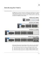
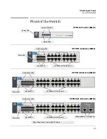
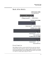
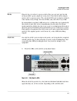
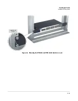
Front of the Switch
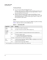
Network Ports
■
8, 16, or 24 auto-sensing 10/100Base-TX ports.
All these ports have the “Auto-MDIX” feature, which means that you can
use either straight-through or crossover twisted-pair cables to connect
any network devices to the switch.
■
(V1410-24-2G Switch only) 2 auto-sensing 10/100/1000Base-T ports.
These ports have the “Auto-MDIX” feature, which means that you can use
either straight-through or crossover twisted-pair cables to connect any
network devices to the switch.
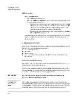
LEDs
The front panels of the switches provide status LEDs for system monitoring.
Table 1-1
details the functions of the LED indicators.
Table 1-1.
Switch Status LEDs
Switch LEDs
State
Meaning
Power
(green)
On
The switch is properly receiving power.
Off
No power connection. The switch is NOT receiving power.
Port LEDs
Link/Act
(green)
On
The port is enabled and receiving a link indication from the connected device.
Off
One of these condition exists:
• no active network cable is connected to the port
• the port is not receiving link beat or sufficient light
Flashing
1
Indicates that there is network activity on the port.
Spd
(green)
On
Indicates the port is operating at 100 Mbps (100 Mbps or 1000 Mbps for ports 25 and
26 on the V1410-24-2G Switch).
Off
Indicates the port is operating at 10 Mbps.
1
The flashing behavior is an on/off cycle once every 0.083 seconds approximately.
Summary of Contents for J9661A
Page 2: ......
Page 3: ...HP V1410 Switch Series Installation and Getting Started Guide ...
Page 8: ...vi Contents ...
Page 34: ...2 20 Installing the Switch Sample Network Topologies ...
Page 50: ...B 2 EMC Regulatory Statements Regulatory Statements Japan VCCI Class A Korea Taiwan ...
Page 58: ...4 Index ...


