background image

© Copyright 2021 HP Development Company,  L.P. 


AMD is a trademark of Advanced Micro Devices,  Inc. Bluetooth is a 

trademark owned by its  proprietor and used by HP Inc. under license. 

NVIDIA is a trademark and/or  registered trademark of NVIDIA 

Corporation in  the U.S. and other countries. USB Type-C and  USB-C are 

registered trademarks of USB  Implementers Forum. DisplayPort and the 

DisplayPort logo are trademarks owned by the  Video Electronics 

Standards Association (VESA)  in the United States and other countries. 


The information contained herein is subject to  change without notice. 

The only warranties for  HP products and services are set forth in the 

express warranty statements accompanying  such products and services. 

Nothing herein  should be construed as constituting an  additional 

warranty. HP shall not be liable for  technical or editorial errors or 

omissions  contained herein. 


First Edition March 2021   
Document Part Number: 920847-E273m-MSG-V1 
Assembly part number: 920847-001 

Product notice


Only trained service personnel familiar with this product should service it. 

Before performing any maintenance or service, be sure to read 

“Important Safety Information”. 

Summary of Contents for EliteDisplay E273m

Page 1: ...Maintenance and Service Guide E273m model SUMMARY This guide provides information about spare parts removal and replacement of parts diagnostic tests problem troubleshooting and more ...

Page 2: ... States and other countries The information contained herein is subject to change without notice The only warranties for HP products and services are set forth in the express warranty statements accompanying such products and services Nothing herein should be construed as constituting an additional warranty HP shall not be liable for technical or editorial errors or omissions contained herein Firs...

Page 3: ... features 3 Features 3 Front components 4 Rear components 6 Locating the serial number and product number 7 3 Illustrated parts catalog 9 How to order parts 10 4 Removal and replacement procedures 11 Preparation for disassembly 11 RC 12 Power board 17 Connector repair 18 Audio connector CN601 20 HDMI connector CN501 20 DP connector CN5101 21 TYPE C connector CN1504 22 D SUB connector CN101 23 Func...

Page 4: ......

Page 5: ...pening the product s cabinet Modules containing electrical components are sensitive to electrostatic discharge ESD Follow ESD safety procedures while handling these parts Some products contain more than one battery Do not disassemble or expose a battery to high temperatures such as throwing into fire or the battery may explode Refer to government requirements for battery recycling or disposal This...

Page 6: ...tance in Electrical and Electronic Equipment Directive is a legal requirement by the EU European Union for the global electronics industry sold in the EU and other countries Any electrical and electronics products launched in the market after June 2006 should meet this RoHS requirement Products launched in the market before June 2006 are not required to be compliant with RoHS parts If the original...

Page 7: ...r andtwodownstreamports connectto USB devices USBBMtoAMcableprovidedtoconnectthemonitor sUSBhubtotheUSBconnectoronthecomputer 23 8 inchmodelonly USBCMtoAMcableprovidedtoconnectthemonitor sUSBhubtotheUSBconnectoronthecomputer 27 inchmodelonly PlugandPlaycapability ifsupportedbyyouroperatingsystem Securitycableslotprovisiononrearofmonitorforoptionalsecuritycable On screendisplay OSD adjustmentsinsev...

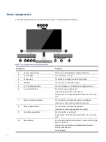
Page 8: ...swer Call button Press to answer or make a call Illuminates green when on the phone Green light and red light blink when there is an incoming call 7 Mute microphone button Press to mute or activate the camera microphone Illuminates amber when microphone is muted 8 Mute speaker button Press to mute or activate the speakers Illuminates amber when speakers are muted 9 Reject Hang up button Press to d...

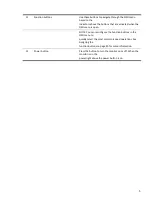
Page 9: ...hen the OSD menu is open NOTE You can reconfigure the Function buttons in the OSD menu to quickly select the most commonly used operations See Assigning the function buttons on page 20 for more information 12 Power button Press the button to turn the monitor on or off When the monitor is on the power light above the power button is on ...

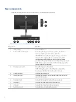
Page 10: ...provided on the optical disc if one is included with your product NOTE When a device is connected to the headphone jack the monitor speakers are disabled 3 Master power switch Turns off all power to the monitor NOTE Putting the switch in the Off position will yield the lowest power state for the monitor when not in use 4 Power connector Connects the power cord 5 USB Type C port Connects the USB CM...

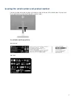
Page 11: ...roduct number The serial number and product number are located on a label on the rear of the monitor panel You may need these numbers when contacting HP about the monitor model For worldwide models except India Barcode label Spec label ...

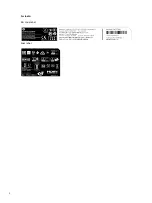
Page 12: ...8 For India Bar code label Spec label ...

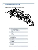
Page 13: ... 3 MIDDLE_FRAME L27WC Bhp1b p1 1 4 LENS 1 5 KEY 1 6 KEY BOARD 1 7 LENS_IR 1 8 KEY_FRAME 1 9 KEY BOARD 1 10 INSULATING SHEET 1 11 ADAPTER BOARD 1 12 INSULATING SHEET 1 13 MAIN BOARD 1 14 USB BOARD 1 15 SHIELD_USB 1 16 MAINFRAME 1 17 SPEAKER 4 1 18 COVER_WEBCAM_FRONT 1 19 SPRING 2 20 KEY BOARD 1 21 SHIELD_IO 1 22 INSULATING SHEET 1 23 WEBCAM MODULE CNFEH5921005040LH 1 ...

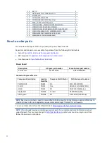
Page 14: ...wer board Description HP spare part number Manufacturer part number PSU E273m M74278 001 ADPCH1965AD2 Connectors by manufacturer Component description Location identifier Component distributor Distributer part number PHONE JACK CN601 RS 913 1021 RS PRO D SUB CN101 tme HDL15 SL B ADAM TECH HDMI CN501 RS SD 47151 001 Molex DisplayPort CN5101 Farnell DP1RD20JQ1 JAE USB Type C CN1504 RS R S13KG 03 CIE...

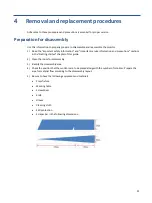
Page 15: ...ce information and precautions sections in the Getting started chapter of this guide 2 Clean the room for disassembly 3 Identify the disassembly area 4 Check the position that the monitors are to be placed along with the number of monitors Prepare the area for material flow according to the disassembly layout 5 Be sure to have the following equipment and materials Press fixture Working table Screw...

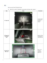
Page 16: ...embly See Preparation for disassembly on page 11 Step Figure Description 1 Preparation Lay the monitor on a flat soft and clean surface 2 Remove the Stand base Ass y Push the button the remove the stand base ass y 3 Remove the Rear cover Remove the screws to remove the Rear cover ...

Page 17: ...13 4 Remove the pin and the screw Remove the pin and the screw 5 Remove the tapes screws and the pins Remove the tapes the screws and the pins ...

Page 18: ...14 6 Remove the screws Remove the screws 7 Remove the screws Remove the screws 8 Remove the Mylar Remove the Mylar ...

Page 19: ... board and power board Remove the screws to remove the main board and power board 10 Remove the connectors Remove the connect pins 11 Remove the screws Remove the screws and the key board Power Board Main Board Main BOARD ...

Page 20: ...16 12 Remove the screws Remove the screws and the camera 13 The mainframe The mainframe 14 The panel The panel ...

Page 21: ...ore removing the power board follow these steps Prepare the monitor for disassembly See Preparation for disassembly on page 11 Remove the power board 1 The HP E273m power board connector position is as follows Power Board Warning After unplugging the power supply the capacitance is still charged do not touch and discharge the capacitor ...

Page 22: ...ocedure includes HDMI DisplayPort TYPE C D SUB and audio connectors The connectors are on the main board board part number CBPCLDWHPQ1 The connectors identifiers are as follows Connector Location HDMI CN501 DisplayPort CN5101 TYPE C CN1504 D SUB CN101 Audio CN601 Power Board ...

Page 23: ...19 Before repairing connectors follow these steps Prepare the monitor for disassembly See Preparation for disassembly on page 11 Main Board Main Board CN601 CN101 CN501 CN5101 CN1504 ...

Page 24: ...cuit board revealed look in good condition After repaired must connect source to each port to check Main board function is ordinary Note The requirement of professional repairers regulation by ERP lot5 1 The professional repairer has the technical competence to repair electronic displays and complies with the applicable regulations for repairers of electrical equipment in the Member States where i...

Page 25: ...he pins 3 Lift the CN501 connector from the PCB 4 Place the new component on the PCB Be sure that it matches the PCB footprint 5 Solder the new component DP connector CN5101 Repair the DP connector 1 Use a soldering iron and a desoldering pump to remove as much solder as possible from the pin 2 Use a hot air gun to melt the solder on the pins ...

Page 26: ...he new component TYPE C connector CN1504 Repair the TYPE C connector 1 Use a soldering iron and a desoldering pump to remove as much solder as possible from the pin 2 Use a hot air gun to melt the solder on the pins 3 Lift the CN1504 connector from the PCB 4 Place the new component on the PCB Be sure that it matches the PCB footprint ...

Page 27: ...a soldering iron and a disordering pump to remove as much solder as possible from the pin 2 Use a hot air gun to melt the solder on the pins 3 Lift the CN101 connector from the PCB 4 Place the new component on the PCB Be sure that it matches the PCB footprint 5 Solder the new component ...

Page 28: ...sconnected Connect the power cord Monitor is off Power the power button NOTE If pressing the Power button has no effect press and hold the power button for 10 seconds to disable the Power button lockout feature Video cable is improperly connected Connect the video cable properly See Connecting the cables on page 7 for more information System is in Sleep mode Press any key on the keyboard or move t...

Page 29: ...are set higher than the monitor supports Change the settings to a supported setting The monitor is off but it did not seem to enter into sleep mode The monitor s power saving control is disabled Open the OSD menu and select Power Control Auto Sleep Mode and set auto sleep to On OSD Lockout is displayed The monitor s OSD Lockout function is enabled Press and hold the Menu button on the front bezel ...

Reviews: