


8
9
7
15
14
16
17
20
19
11
12
13
2
10
18
hp
designjet copier cc
800ps
hp
designjet co
pier cc800p
s
hp
designjet co
pier cc800p
s
E
X
T
E
N
D
E
D
E
X
I
T
E
X
I
T
N
O
R
M
A
L
E
X
T
E
N
D
E
D
N
O
R
M
A
L
Inc
hes
mm
0.6
3
0.5
5
0.4
7
0.3
9
0.3
1
0.2
4
0.1
6
0.0
8
16
14
12
10
8
6
4
2
EX
TE
ND
ED
EX
IT
EX
IT
NO
RM
AL
EX
TE
ND
ED
NO
RM
AL
In
ch
es
mm
0.6
3 0.550
.470
.390
.310
.240
.160
.08
16
14
12
10
8
6
4
2
hp
designjet cop
ier cc800ps
E
X
T
E
N
D
E
D
E
X
I
T
E
X
I
T
N
O
R
M
A
L
E
X
T
E
N
D
E
D
N
O
R
M
A
L
Inc
hes
mm
0.6
3
0.5
5
0.4
7
0.3
9
0.3
1
0.2
4
0.1
6
0.0
8
16
14
12
10
8
6
4
2
EX
TE
ND
ED
EX
IT
EX
IT
NO
RM
AL
EX
TE
ND
ED
NO
RM
AL
In
ch
es
mm
0.6
3 0.550
.470
.390
.310
.240
.160
.08
16
14
12
10
8
6
4
2
E X T E N D E D
E X I T
E X I T
N O R M A L
E X T E N D E D
N O R M A L
Inches
mm
0.6
3
0.
55
0.
47
0.3
9
0.3
1
0.
24
0.
16
0.0
8
16
14
12
10
8
6
4
2
E
X
T
E
N
D
E
D
E
X
I
T
E
X
I
T
N
O
R
M
A
L
E
X
T
E
N
D
E
D
N
O
R
M
A
L
In
ch
es
m
m
0.
63
0.
55
0.
47
0.
39
0.
31
0.
24
0.
16
0.
08
16
14
12
10
8
6
4
2
E
X
T
E
N
D
E
D
E
X
I
T
E
X
I
T
N
O
R
M
A
L
E
X
T
E
N
D
E
D
N
O
R
M
A
L
Inc
hes
mm
0.6
3
0.5
5
0.4
7
0.3
9
0.3
1
0.2
4
0.1
6
0.0
8
16
14
12
10
8
6
4
2
EX
TE
ND
ED
EX
IT
EX
IT
NO
RM
AL
EX
TE
ND
ED
NO
RM
AL
In
ch
es
mm
0.6
3 0.550
.470
.390
.310
.240
.160
.08
16
14
12
10
8
6
4
2
E
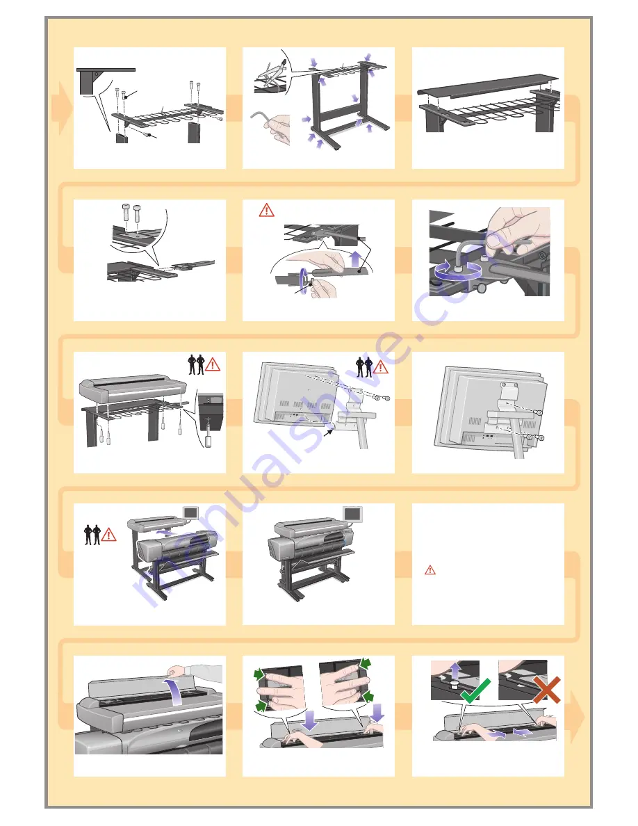
Position your fingers in the 4 lock slots (2 at
each end of the platen indicated by the green
arrows above), and press down (blue arrows).
With the platen pushed down, slide the 2
locks inwards until the pins at either end pop
up locking the platen open and ready to be
removed.
Fasten the top bar and wire guide to the 2 legs
using 4 M6X30 and 2 M6X10 screws.
Connect the rear table: this is fitted by
locating the 4 guide pins on the rear of the
table into the rubber framed holes on the top
bar.
Attach the front panel arm by sliding the arm's
mount onto the top bar, aligning the holes,
and fixing
lightly
with 2 M4X25 screws.
Lift the front panel arm and tighten the
2
finger screws.
Tighten the
2
M4X25 screws firmly.
Lift the scanner into place, locating the rubber
feet in the holes indicated, and fixing with the
4 slotted special screws.
Rest the front panel onto
the narrow shelf and
attach with 2 M4X8 screws where shown.
Narrow shelf
Cleaning the Scan Area...
You are now required to clean the scan
area, to do so you will need the cleaning
tools provided in the maintenance kit and a
cleaning fluid (not included in the
maintenance kit).
Caution:
do not use abrasives,
acetone, benzene or fluids that contain
these chemicals. Do not spray liquids
directly onto the scanner glass plate or
anywhere else in the scanner.
Attach with 3 more M4X8 screws as shown.
Slide the
assembled printer
under the designjet
copier. The printer's
stand feet will be positioned on the outer sides
of the copier's.
The unit is now assembled and should appear
like the above illustration.
Open the scanner cover to expose the scan
area.
Take care when tightening as this
item can slip.
M6X30
M6X10
Remove the plastic safety tie and tighten up all
screws firmly.
Front
panel
arm
Tighten (X2)


