HP Cray CS E1000, Disassembly Instructions Manual
The HP Cray CS E1000 Disassembly Instructions Manual is a comprehensive user guide that showcases step-by-step instructions for the proper disassembly of the product. Easily downloadable for free, this manual can be obtained from manualshive.com and serves as an essential resource for maintenance and troubleshooting.
Share
Download


Reviews:
No comments
Related manuals for Cray CS E1000

Cheetah 15K.7 SAS ST3300557SS
Brand: Seagate Pages: 76

UltraHD 20296
Brand: Seville Classics Pages: 7

Duramax Yardmate
Brand: USP Pages: 25

Q2S-3H-15T
Brand: Kanguru Pages: 12

STFS500400
Brand: LaCie Pages: 26

HA201-AP
Brand: AIC Pages: 64

PTA 2000
Brand: Bosch Pages: 76

GTA 2500 Compact Professional
Brand: Bosch Pages: 84

706.366440
Brand: Craftsman Pages: 8

706.105950
Brand: Craftsman Pages: 4

76637
Brand: Craftsman Pages: 13

evolv F1711
Brand: Craftsman Pages: 6
120.29687
Brand: Craftsman Pages: 3
120.29684
Brand: Craftsman Pages: 4

18383
Brand: Craftsman Pages: 8

31016
Brand: Craftsman Pages: 8

31013
Brand: Craftsman Pages: 8

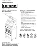
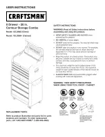
CORNER SHELVING UNIT
Brand: Craftsman Pages: 12


