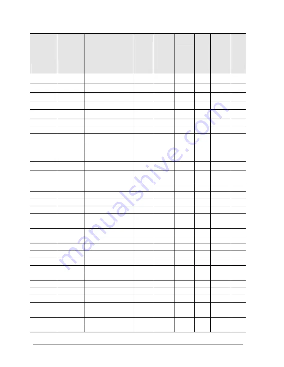
background image


4-20 

Replaceable Parts 

Service Manual 

Part 

Description 

Exchange 
Part  
Number 

Description 

Pavilion 

ze5x00, 

nx9010, 

nx9008 

and  

Presario 

2500 

Pavilion 

ze4x00, 

nx9005, 

Evo  

N1050v 

and  

Presario 

2100 

Pavilion 

ze4200, 

nx9000 

and  

Presario 

2100 

Evo  

N1010

and  

Presari

o 1100 

F5771J 

Pavilion 

ze4100 

H5761H 

User 
Repl 

319848-001  

SPS-PROC ATH  
1

.

53-GHz 45W 


• 


No 

319849-001  

SPS-PROC ATH  
1

.

67-GHz 45W 


• 


No 

319850-001  

SPS-PROC ATH  
1

.

46-GHz 45W 


• 


No 

320691-001  

SPS-DRV DSKT 144 MB 3F 

• 


No 

320692-001  

SPS-DRV HD 80 G 
(4200 rpm) 

• 

• 

• 


Yes 

322998-001  

SPS-CASE TOP 3F CPQ DF 

• 


No 

322998-001  

SPS-CASE, TOP 3F PAV DF 

• 


No 

323099-001  

SPS-COVER, KEYBOARD 
W/SPEAKERS PAV 

• 


No 

323222-001  

SPS-PROC 24 GHz  
400 MHz FSB 

• 


No 

323223-001  

SPS-PROC 24 GHz  
533 MHz FSB 

• 


No 

F4600-60901  

AC-Adapter-Ultraslim Delta 
75W s/PFC 


• 

• 

Yes 

F4640-60901  

Cover, mem or  
Mini PCI–1F  
w/ labels 


• 

• 

• 

• 

Yes 

F4640-60903  

Tray, 

HDD–1F 


• 

• 

• 

• 

Yes 

F4640-60908  

Speaker 

assy–1F 


• 

• 

• 


No 

F4640-60909  

SPS-KEYBOARD-AR 


• 

• 


No 

F4640-60910  

SPS-KEYBOARD-BEL 


• 

• 


No 

F4640-60911  

SPS-KEYBOARD-CZ 


• 

• 


No 

F4640-60912  

SPS-KEYBOARD-DEN 


• 

• 


No 

F4640-60913  

Keybd, FRENCH 


• 

No 

F4640-60914  

SPS-KEYBOARD-FC 


• 

• 


No 

F4640-60915  

Keybd, GERMAN 


• 


No 

F4640-60916  

SPS-KEYBOARD-GRK 


• 

• 


No 

F4640-60917  

SPS-KEYBOARD-HE 


• 

• 


No 

F4640-60918  

SPS-KEYBOARD-HUN 


• 

• 


No 

F4640-60920  

SPS-KEYBOARD-INTL 

• 

• 

• 


No 

F4640-60921  

Keybd, ITALIAN 


• 

• 

• 


No 

F4640-60922  

Keybd, JAPANESE 


• 

• 

• 


No 

F4640-60923  

SPS-KEYBOARD-NO 


• 

• 


No 

F4640-60924  

SPS-KEYBOARD-PT 


• 

• 


No 

F4640-60925  

SPS-KEYBOARD-RU 


• 

• 


No 

F4640-60926  

Keybd, SPANISH 


• 

No 

F4640-60927  

SPS-KEYBOARD-SWE 


• 

• 


No 

Summary of Contents for Compaq Evo N1010v series

Page 1: ...n ze4400 Notebook PC HP Pavilion ze4300 Notebook PC HP Pavilion ze4200 Notebook PC HP Pavilion ze4100 Notebook PC HP Compaq nx9010 Notebook PC HP Compaq nx9008 Notebook PC HP Compaq nx9005 Notebook PC HP Compaq nx9000 Notebook PC Compaq Evo Notebook N1050v Series Compaq Evo Notebook N1010v Series Compaq Presario 2500 Series Mobile PC Compaq Presario 2100 Series Mobile PC Compaq Presario 1100 Serie...

Page 2: ...countries The information contained herein is subject to change without notice The only warranties for HP products and services are set forth in the express warranty statements accompanying such products and services Nothing herein should be construed as constituting an additional warranty HP shall not be liable for technical or editorial errors or omissions contained herein Service Manual Fourth ...

Page 3: ...rd PCA 2 19 Removing the CD DVD Drive 2 20 Removing the Display Assembly 2 23 Removing the Top Case 2 26 Removing the Floppy Drive 2 32 Removing the Infrared I R PCA 2 36 Removing the Audio PCA 2 38 Removing the Heat Sink with Fan 2 40 Removing the CPU Module 2 44 Removing the RJ11 1394 Connector Module 2 48 Removing the Motherboard 2 50 Replacing Components on a Bottom Case 2 59 Repairing the BIO...

Page 4: ...CA 2 18 Figure 2 14 Removing the Switchboard PCA 2 19 Figure 2 15 Removing the CD DVD Drive 2 21 Figure 2 16 Removing the CD DVD Drive 2 22 Figure 2 17 Removing the Display Assembly 2 24 Figure 2 18 Removing the Top Case 2 27 Figure 2 19 Removing the Top Case Screws 2 29 Figure 2 20 Removing the Top Case Screws 2 30 Figure 2 21 Removing the Top Case 2 31 Figure 2 22 Removing the Floppy Drive 2 33 ...

Page 5: ...1 15 Table 1 5 Fn Hot Keys 1 16 Table 1 6 Specifications 1 18 Table 1 7 Accessories 1 22 Table 1 8 Functional Structure Description 1 25 Table 2 1 Removal Cross Reference 2 1 Table 2 2 Required Equipment 2 2 Table 2 3 Recommended Screw Torque Values 2 2 Table 2 4 Replacing Small Parts 2 12 Table 2 5 Removing Components 2 63 Table 3 1 ASP Support Options 3 2 Table 3 2 Scope of Diagnostic Tools 3 7 ...

Page 6: ... even without having equipment available The following table lists other sources of information about the notebook computers and related products Source Address or Number Comments HP Notebook Web site Compaq Notebook Web site http www hp com notebooks http welcome hp com country us eng prodserv notebooks_tabletpcs html HP Business Support Web site http www hp com go bizsupport HP Asia Pacific Chan...

Page 7: ...SXGA 1024 768 active matrix TFT Video ATI Mobility Radeon graphics accelerator with 16 32 or 64 MB UMA graphics memory 4x AGP graphics capability Operating System Microsoft Windows XP Professional or Home preinstalled Power States On Standby Hibernate Off HP Pavilion ze5500 Processor Intel Celeron 2 6 GHz Mobile Intel Pentium 4 2 4 2 66 2 8 and 3 06 GHz Memory Up to 1 GB 1024 MB SDRAM using 512 MB...

Page 8: ...B SDRAM using 512 MB modules At least 256 MB SDRAM preinstalled Display 15 0 inch XGA 1024 768 or SXGA 1400 1050 or 14 1 inch XGA 1024 768 active matrix TFT Video ATI Mobility Radeon graphics accelerator with 16 32 or 64 MB UMA graphics memory 4x AGP graphics capability Operating System Windows XP Professional or Home preinstalled Power States On Standby Hibernate Off HP Pavilion ze4700 Processor ...

Page 9: ...GB 1024 MB SDRAM using 512 MB modules At least 128 MB SDRAM preinstalled Display 15 0 inch XGA 1024 768 or 14 1 inch XGA 1024 768 active matrix TFT Video ATI Mobility Radeon graphics accelerator with 16 32 or 64 MB UMA graphics memory 4x AGP graphics capability Operating System Windows XP Professional or Home preinstalled Power States On Standby Hibernate Off HP Pavilion ze4400 Processor AMD Athlo...

Page 10: ...D Athlon 1 47 1 53 1 6 1 67 and 1 8 GHz Memory Up to 512 MB SDRAM using 256 MB modules At least 128 MB SDRAM preinstalled Display 15 0 inch XGA 1024 768 or SXGA 1400 1050 or 14 1 inch XGA 1024 768 active matrix TFT Video ATI Mobility Radeon graphics accelerator with 16 32 or 64 MB UMA graphics memory 4x AGP graphics capability Operating System Windows XP Professional or Home preinstalled Power Sta...

Page 11: ...alled Display 14 1 inch XGA 1024 768 active matrix TFT Video ATI Mobility Radeon graphics accelerator with 16 32 or 64 MB UMA graphics memory 4x AGP graphics capability Operating System Windows XP Professional or Home preinstalled Power States On Standby Hibernate Off HP Compaq nx9005 Processor Mobile Intel Pentium 4 M 1 8 2 0 2 2 and 2 4 GHz Intel Celeron 1 8 2 0 and 2 2 GHz AMD Athlon 1 47 1 53 ...

Page 12: ...GB 1024 MB SDRAM using 512 MB modules At least 256 MB SDRAM preinstalled Display 15 0 inch XGA 1024 768 or 14 1 inch XGA 1024 768 active matrix TFT Video ATI Mobility Radeon graphics accelerator with 16 32 or 64 MB UMA graphics memory 4x AGP graphics capability Operating System Windows XP Professional or Home preinstalled Power States On Standby Hibernate Off Compaq Evo Notebook 1010v Processor In...

Page 13: ...thlon 1 46 1 53 1 67 and 1 8 GHz AMD Athlon XP M 1 87 2 0 GHz Memory Up to 1 GB 1024 MB SDRAM using 512 MB modules At least 128 MB SDRAM preinstalled Display 15 0 inch XGA 1024 768 or SXGA 1400 1050 or 14 1 inch XGA 1024 768 active matrix TFT Video ATI Mobility Radeon graphics accelerator with 16 32 or 64 MB UMA graphics memory 4x AGP graphics capability Operating System Windows XP Professional or...

Page 14: ...aq Presario 2100 and 1100 1 Notebook open close latch 2 One touch buttons 3 Keyboard status lights 4 Power button turns the notebook on and off 5 Touch pad scroll pad Select buttons plus on off button 6 Main status lights left to right power mode hard disk activity and battery 7 Microphone option not available 8 Infrared port 9 Wireless on off button and indicator light 10 Battery 11 CD ROM DVD or...

Page 15: ...o port 17 Parallel port LPT1 use this port for a parallel printer or other parallel device 18 Serial port COM1 use this port for a serial mouse modem printer or other serial device 19 External monitor port 20 Kensington lock slot security connector 21 Modem port 22 PCMCIA card and CardBus slot and button 23 IEEE 1394 port 24 Audio jacks left to right external microphone and audio out headphones 25...

Page 16: ...P Pavilion ze4x00 HP Compaq nx9005 and nx9000 Compaq Evo Notebook N1050v and N1010v and Compaq Presario 2100 and 1100 28 Hard disk drive 29 Battery latch 30 SDRAM door 31 Reset button 32 Port replicator connect 33 Mini PCI door no user parts inside on certain models ...

Page 17: ...ebook on and off 5 Touch pad scroll pad Select buttons plus on off button 6 Main status lights left to right power mode hard disk activity and battery 7 Infrared port 8 Wireless on off button and indicator light 9 Audio mute button and audio mute light 10 Battery 11 Volume controls 12 Audio jacks left to right external microphone and audio out headphones 13 CD ROM DVD or other drive 14 Universal S...

Page 18: ... universal Serial Bus USB ports 17 LAN port 18 External keyboard mouse port 19 Parallel port LPT1 use this port for a parallel printer or other parallel device 20 External monitor port 21 S Video port 22 Kensington lock cable slot security connector 23 Modem port 24 IEEE 1394 port 25 PCMCIA card and CardBus slot and button 26 Floppy drive on certain models ...

Page 19: ...Figure 1 6 Bottom View HP Pavilion 5x00 HP Compaq nx9010 and nx9008 and Compaq Presario 2500 27 Hard disk drive 28 Battery latch 29 Mini PCI door no user parts inside 30 SDRAM door 31 Port replicator connect 32 Reset button on certain models ...

Page 20: ...M Restarts quickly Restores network connections Power mode status light blinks Press the power button or select Start Turn Off Computer Stand By Windows XP or select Start Shut Down Standby Windows 2000 or allow timeout Hibernation mode Saves maximum power Saves current session to disk and then shuts down Restores network connections Power mode status light is off Press Fn F12 or select Start Shut...

Page 21: ...us Green The AC adapter is connected and the battery is fully charged Amber The AC adapter is connected and the battery is charging Blinking The AC adapter is connected and the battery is missing or has a fault Off The AC adapter is not connected The keyboard status lights located above the keyboard indicate the states of the keyboard locks Table 1 4 Keyboard Status Lights Meaning Caps Lock Caps L...

Page 22: ...Fn F2 Increases the display brightness Fn F5 Toggles among the built in display an external display and simultaneous display on both Fn F8 Toggles the built in keypad on and off Does not affect an external keyboard If Num Lock is on then the numeric functions are active otherwise cursor control is active as marked on an external keyboard Fn F12 Enters Hibernation mode Fn NumLock Toggles Scroll Loc...

Page 23: ...he system will not allow a software shutdown press and hold down the power button until the display shuts down about 4 seconds and then release the power button Press the power button again to restart Use a ballpoint pen or a straightened paper clip to press the reset button on the bottom of the notebook Figure 1 7 Resetting the Notebook NOTE To boot from a CD insert a bootable CD such as the Reco...

Page 24: ...tel Speed Step technology 512 KB L2 cache and 1 2 to 1 3 V core low power processor with 400 MHz processor system bus or 2 6 GHz Mobile Intel Celeron processor with 128 KB L2 cache and 1 45 V core low power processor with 400 MHz processor system bus HP Pavilion ze5400 or ze5300 2 4 2 53 2 66 or 2 8 GHz Intel Pentium 4 processor D or 2 4 2 53 2 66 or 2 8 GHz Mobile Intel Pentium 4 with Intel Speed...

Page 25: ... or 1 6 1 7 1 8 or 2 0 GHz Intel Celeron processor with 256 KB L2 cache and 1 45 V core low power processor with 133 MHz processor system bus or 1 46 1 53 1 67 or 1 80 GHz AMD Athlon processor with 256 KB L2 cache and 1 45 V core low power processor with 133 MHz processor system bus Compaq Presario 1100 1 6 or 1 8 GHz Intel Celeron processor with 256 KB L2 cache and 1 45 V core low power processor...

Page 26: ...PC2100 DDR 266 SDRAM modules Up to 512 MB SDRAM using 256 MB modules Audio System Stereo sound via 2 built in speakers 3D enhanced audio Volume and mute buttons certain models Headphone out and microphone in Keyboard and Pointing Device 87 88 key touch type QWERTY keyboard with 101 102 key emulation Embedded numeric keypad 12 function Fn keys 5 user programmable One Touch buttons Touch pad with in...

Page 27: ...ATA100 0950 4162 319413 001 HDD 30 GB 9 5mm IBM diablo ATA100 0950 4319 HDD 30 GB 9 5mm IBM ATA100 FDB Cascade 0950 4360 HDD 30 GB 9 5mm TITAN Toshiba ATA100 TITAN 0950 4176 HDD 30 GB 9 5mm Toshiba ATA100 0950 4320 319414 001 HDD 40 GB 9 5mm IBM ATA100 FDB 0950 4288 HDD 40 GB 9 5mm Toshiba ATA100 319415 001 SPS DRV HD 60 GB 4200 rpm 319416 001 SPS DRV HD 60 GB 5400 rpm 320692 001 SPS DRV HD 80 GB ...

Page 28: ...317444 AA1 Cord Pwr People s Republic of China AB2 2w 317444 101 SPS CORD AC PWR 2 WIRE SWE 317444 111 SPS CORD AC PWR 2 WIRE SWI 317444 AB1 SPS CORD AC PWR 2 WIRE TAI 8120 8699 317444 031 Cord Pwr UK EPSR for Hong Kong 2w 8120 6313 317444 001 Cord Pwr US ABA 2w PC Cards F4640 60978 319468 051 Card Mini PCI 802 11B France F4640 60977 319468 002 Card Mini PCI 802 11B worldwide Docking F4808 60901 P...

Page 29: ...le in virtually all system functions The CPU module and most other subsystems connect to the motherboard The following figure shows the connections among the notebook s replaceable electronic modules Table 1 8 on page 1 25 lists the roles that these modules play in the notebook s functional subsystems Figure 1 8 Replaceable Module Diagram ...

Page 30: ...tch one touch buttons Key switches PS 2 TouchPad Motherboard Top case Keyboard circuitry keyboard controller keyboard BIOS Touch pad sensor Select buttons controller PS 2 output Audio Motherboard Speaker assembly Audio controller audio decoder speaker amplifier microphone external audio jacks headphone amplifier audio off switch Speakers Status Motherboard Switchboard PCA Top case LED circuitry ke...

Page 31: ...with fan page 2 40 Keyboard page 2 16 Module CPU page 2 44 Module RJ11 1394 page 2 48 Module SDRAM page 2 5 PCA antennas page 2 60 PCA audio page 2 38 PCA I R page 2 36 PCA motherboard page 2 50 PCA switchboard page 2 19 Rubber screw plugs display page 2 12 CAUTION Always provide proper grounding when performing repairs Without proper grounding an electrostatic discharge can damage the notebook an...

Page 32: ... screwdrivers preferably magnetized Small flat blade screwdriver 5mm nut driver Table 2 3 Recommended Screw Torque Values Screw Thread Size Torque cm kgf Torque in lbf M2 2 0 2 5 1 7 2 2 M2 5 hinges 3 5 4 0 3 0 3 4 M2 5 other 2 5 3 0 2 2 2 6 M3 2 5 3 0 2 2 2 6 Standoff hex 2 5 3 0 2 2 2 6 ...

Page 33: ...Manual Removal and Replacement 2 3 Disassembly Flowchart The following diagram shows the general path you will use when disassembling the notebook to access any particular component Figure 2 1 Disassembly Flow ...

Page 34: ...placement Service Manual Removing the Battery User Replaceable Required Equipment None Removal Procedure Slide the battery s release latch and then pull the battery out of its compartment Figure 2 2 Removing the Battery ...

Page 35: ... from booting CAUTION Handle the SDRAM module only by its edges and provide proper grounding or you might damage the module through electrostatic discharge Required Equipment 1 Phillips screwdriver Removal Procedure 1 Unplug the AC adapter if present and then remove the battery 2 On the bottom of the notebook loosen the captive screws holding the SDRAM door and then remove the door 3 Press outward...

Page 36: ...in Figure 2 4 The procedure for removing the SDRAM door and modules is the same for all notebook models Figure 2 4 Removing an SDRAM Module HP Pavilion ze5x00 HP Compaq nx9010 nx9008 and Compaq Presario 2500 Models Reassembly Notes Carefully press the SDRAM module into the connector at an angle of about 30 until it is fully inserted and then press down on both sides of the SDRAM module until the l...

Page 37: ...e the battery 2 On the bottom of the notebook loosen the captive screws holding the Mini PCI door and then remove the door CAUTION Be careful when connecting and disconnecting the antenna cables from the Mini PCI card Damaged cables or connectors can degrade notebook performance 3 Disconnect the 2 antenna cables from the Mini PCI card 4 Press outward on the latches at the sides of the Mini PCI car...

Page 38: ...d in Figure 2 6 The procedure for removing the Mini PCI door and card is the same for all notebook models Figure 2 6 Removing the Mini PCI Card HP Pavilion ze5x00 HP Compaq nx9010 and nx9008 and Compaq Presario 2500 Models Reassembly Notes Carefully press the Mini PCI card into the connector at an angle of about 30 until it is fully inserted and then press down on both sides of the Mini PCI card u...

Page 39: ...tware and operating system on the drive as described in Recovering the Factory Software as shown on the next page 1 Unplug the AC adapter if present and then remove the battery 2 On the bottom of the notebook remove the hard disk drive rubber screw plugs and M2 5 6 0mm screws The number of plugs and screws varies by model 3 Carefully pull the hard disk drive out of the notebook Figure 2 7 Removing...

Page 40: ... 0mm screws from the hard disk drive and hard disk drive tray and then lift the drive out of the tray 5 Remove the connector bar from the hard disk drive NOTE Connector bar not used on HP Pavilion ze5x00 series Figure 2 8 Removing the Hard Disk Drive Tray See note below ...

Page 41: ...o select the CD DVD drive as the first boot device and then press enter 6 When the dialog box appears follow the displayed instructions If prompted accept the recommended partition size To create the Utility partition without installing the factory software select Advanced and then select not to install the operating system If the hard disk is partitioned into several logical drives you can instal...

Page 42: ...d then remove the door Door memory On the bottom of the notebook loosen the screws that secure the SDRAM module door to the bottom case and then remove the door Feet rubber on bottom of notebook Insert a small flat blade screwdriver under the foot and pry it loose To replace firmly press the adhesive side of the foot into the recess Rubber cover docking port ze4500 only Grasp the rubber docking po...

Page 43: ...r to the rear of the notebook 3 Carefully insert a flat blade screwdriver blade under the keyboard cover near the right end then near the center then near the left end and then gently lift up the center of the cover Gently pry up the hinge covers if needed being careful not to damage the plastics or wireless antenna underneath CAUTION Be careful not to damage the antenna PCA that is connected to t...

Page 44: ... the left side of display assembly hinge to completely remove the cover Figure 2 9 Removing the Keyboard Cover NOTE When removing the keyboard cover on HP Pavilion 5300 and 5200 HP Compaq nx9010 and Compaq Presario 2500 models disconnect the speaker cable as indicated in Figure 2 10 Figure 2 10 Disconnecting the Speaker Cable Reassembly Note Insert the tabs on the left and right center of the pane...

Page 45: ...eakers are integrated into the top case Refer to the Removing the Top Case section later in this chapter for procedures on removing the top case and speakers on the HP Pavilion 5x00 HP Compaq nx9010 and nx9008 and Compaq Presario 2500 Series notebooks Required Equipment 1 Phillips screwdriver Removal Procedure 1 Unplug the AC adapter if present and then remove the battery 2 Remove the keyboard cov...

Page 46: ... PCA end and then pull it toward the display assembly to release the tabs from the top case 5 Turn the keyboard over and then disconnect the motherboard cable 6 Remove the keyboard Reassembly Notes CAUTION Do not excessively bend or fold the keyboard cable Excessive flexing can damage the keyboard cable connectors Lay the keyboard face down on the top case forward of its normal position and then r...

Page 47: ...Service Manual Removal and Replacement 2 17 Figure 2 12 Removing the Keyboard ...

Page 48: ... keyboard cover page 2 13 3 Disconnect both the 2 wire and 4 wire cables that connect the switchboard PCA to the top case and speaker assembly respectively 4 Remove the M2 5 4 0mm screw that secures the keyboard and then switchboard PCA to the top case page 2 16 5 Gently lift up on the keyboard carefully remove the switchboard PCA from the top case and then disconnect the underside motherboard cab...

Page 49: ...battery 2 Remove the keyboard cover page 2 13 3 Disconnect the 2 wire cable that connects the switchboard PCA to the display lid switch 4 Remove the two M2 5 4 0mm screws that secure the switchboard PCA to the top case 5 Gently lift up on the rear right edge of the switchboard PCA to disconnect the PCA from the motherboard 6 Remove the switchboard PCA Figure 2 14 Removing the Switchboard PCA HP Pa...

Page 50: ... 3 Remove the 2 screws that secure the CD DVD drive to the top case and motherboard NOTE The screws that secure the CD DVD drive are 2 different sizes The front screw is a M2 5 6 0mm screw The back screw is a M2 5 4 0mm screw Make sure these screws are installed in the correct locations when reinstalling the CD DVD drive 4 Place your index finger in the top case opening and then push out on the CD...

Page 51: ...n remove the battery 2 Remove these additional assemblies Keyboard cover page 2 13 Keyboard page 2 16 3 Remove the two M2 5 6 0mm screws that secure the CD DVD drive to the top case and motherboard 4 Place your index finger in the top case opening and push out on the CD DVD drive to release it from the motherboard 5 Remove the CD DVD drive Figure 2 16 Removing the CD DVD Drive HP Pavilion 5x00 HP ...

Page 52: ...Remove the two M2 5 6 0mm retaining screws from the notebook rear panel 4 Remove the M2 5 4 0mm screws from the left and right antenna PCAs Relocate the antenna PCAs away from the display assembly hinges 5 Disconnect the display assembly cable from the motherboard 6 Remove the six M2 5 6 0mm retaining screws that secure the display assembly to the top case Note that there is a grounding strap at t...

Page 53: ...floppy disk as described in the package s Readme file 2 Plug in an AC adapter 3 Insert the Service Utilities floppy disk in the floppy drive If the unit has no internal floppy drive connect a USB floppy drive 4 Turn on the notebook 5 When you see the HP logo press esc to display the boot menu then boot from the floppy drive 6 Select the option to update the display LCD identification stored on the...

Page 54: ...eyboard cover page 2 13 Speaker assembly page 2 23 Keyboard page 2 16 Switchboard PCA page 2 19 CD DVD drive page 2 20 Display assembly page 2 23 3 Turn the notebook bottom side up with the front facing forward 4 Remove the following M2 5 4 0mm screws One from the battery bay One from the hard disk drive bay 5 Remove the remaining 14 M2 5 6 0mm screws 6 Turn the notebook top side up with the rear ...

Page 55: ...Service Manual Removal and Replacement 2 25 Figure 2 18 Removing the Top Case HP Pavilion 4x00 HP Compaq nx9005 and nx9000 Compaq Evo Notebook N1050v and N1010v and Compaq Presario 2100 and 1100 Models ...

Page 56: ...ay assembly page 2 23 3 Turn the notebook bottom side up with the front facing forward 4 Remove the following 16 screws Six M2 5 7 0mm screws on the rear edge of the notebook Two M2 5 6 0mm screws on each side of the docking connector One M2 5 6 0mm screw behind the battery bay Three M2 5 7 0mm screws around the middle fan vent One M2 5 4 0mm screw in the battery bay Three M2 5 7 0mm screws on the...

Page 57: ...ompaq nx9010 and nx9008 and Compaq Presario 2500 Models 5 Turn the notebook top side up with the rear panel facing forward 6 Remove the two M2 5 7 0mm screws from the rear of the bottom case Figure 2 20 Removing the Top Case Screws HP Pavilion 5x00 HP Compaq nx9010 and nx9008 and Compaq Presario 2500 Models ...

Page 58: ...4 screws One M2 5 7 0mm screw next to the TouchPad cable Two M2 5 6 0mm screws in the center of the top case One M2 5 4 0mm screw on the right side of the top case CAUTION The 4 screws removed in step 10 are 3 different lengths Be sure to note of the correct location of each screw as it is removed and install it in the correct location Failure to follow this caution can result in damage to the not...

Page 59: ... remove the battery 2 Remove these additional assemblies Hard disk drive page 2 9 Keyboard cover page 2 13 Keyboard page 2 16 Switchboard PCA page 2 19 Display assembly page 2 23 Top case page 2 26 3 Remove the two M2 5 4 0mm screws right side that secure the hard disk drive guide to the motherboard Note that the screws left side are missing These screws were removed during the top case removal pr...

Page 60: ...y Notes CAUTION Do not excessively bend or fold the floppy drive cable Excessive flexing can damage the floppy drive cable connections Connect the floppy drive cable to the motherboard prior to replacing the floppy drive and hard disk drive guide When replacing the hard disk drive guide do not secure the left side to the motherboard The left side of the guide gets secured during the top case repla...

Page 61: ...semblies Hard disk drive page 2 9 Keyboard cover page 2 13 Keyboard page 2 16 Switchboard PCA page 2 19 Display assembly page 2 23 Top case page 2 26 3 Remove the insulating tape that secures the floppy drive flex cable to the TouchPad bracket on the top case 4 Remove the four M2 5 6 0mm screws that secure the floppy drive and floppy drive bezel to the top case 5 Remove the floppy drive 6 Remove t...

Page 62: ... 2 23 Removing the Floppy Drive HP Pavilion 5x00 HP Compaq nx9010 and nx9008 and Compaq Presario 2500 Models Reassembly Notes CAUTION Do not excessively bend or fold the floppy drive cable Excessive flexing can damage the floppy drive cable connections ...

Page 63: ...equired Equipment 1 Phillips screwdriver Removal Procedure 1 Unplug the AC adapter if present and then remove the battery 2 Remove these additional assemblies Hard disk drive page 2 9 Keyboard cover page 2 13 Keyboard page 2 16 Switchboard PCA page 2 19 Display assembly page 2 23 Top case page 2 26 ...

Page 64: ...2 5 4 0mm screws that secure the I R PCA to the bottom case 5 Remove the I R PCA Figure 2 24 Removing the I R PCA Reassembly Note CAUTION Use care when handling the I R PCA cable Damaging the cable can degrade notebook performance Make sure you route the I R PCA cable between the left screw hole and the bottom case ...

Page 65: ...ure 1 Unplug the AC adapter if present and then remove the battery 2 Remove these additional assemblies Hard disk drive page 2 9 Keyboard cover page 2 13 Keyboard page 2 16 Switchboard PCA page 2 19 Display assembly page 2 23 Top case page 2 26 3 Disconnect the audio PCA cable from the motherboard 4 Remove the audio PCA cable from the clip on the bottom case 5 Remove the two M2 0 3 0mm flathead sc...

Page 66: ...secures the audio PCA to the bottom case 8 Remove the audio PCA Figure 2 25 Removing the Audio PCA Reassembly Note CAUTION Use care when handling the audio PCA cable Damaging the cable can degrade notebook performance Make sure you route the audio PCA cable into the clip on the bottom case ...

Page 67: ...Compaq Evo Notebook N1050v and N1010v and Compaq Presario 2100 and 1100 models Required Equipment 0 Phillips screwdriver Removal Procedure 1 Unplug the AC adapter if present and then remove the battery 2 Remove these additional assemblies Hard disk drive page 2 9 Keyboard cover page 2 13 Keyboard page 2 16 Switchboard PCA page 2 19 Display assembly page 2 23 Top case page 2 26 ...

Page 68: ...nx9000 Compaq Evo Notebook N1050v and N1010v and Compaq Presario 2100 and 1100 Models CAUTION Do not spin the fan blades with your finger or you could damage the fan s bearings Reassembly Notes If the thermal pad is damaged use a sharp knife or scraper to carefully remove it from the heat sink and then attach a new thermal pad Install the heat sink screws in this order 1 Install all 3 screws light...

Page 69: ...d Compaq Presario 2500 models Required Equipment 0 Phillips screwdriver Removal Procedure 1 Unplug the AC adapter if present and then remove the battery 2 Remove these additional assemblies Hard disk drive page 2 9 Keyboard cover page 2 13 Keyboard page 2 16 Switchboard PCA page 2 19 Display assembly page 2 23 Top case page 2 26 ...

Page 70: ... Fan HP Pavilion 5x00 HP Compaq nx9010 and nx9008 and Compaq Presario 2500 Models CAUTION Do not spin the fan blades with your finger or you could damage the fan s bearings Reassembly Notes If the thermal pad is damaged use a sharp knife or scraper to carefully remove it from the heat sink and then attach a new thermal pad Install the heat sink screws in this order 1 Install all 4 screws lightly 2...

Page 71: ...ilion 4x00 HP Compaq nx9005 and nx9000 Compaq Evo Notebook N1050v and N1010v and Compaq Presario 2100 and 1100 models Removal Procedure 1 Unplug the AC adapter if present and then remove the battery 2 Remove these additional assemblies Hard disk drive page 2 9 Keyboard cover page 2 13 Keyboard page 2 16 Switchboard PCA page 2 19 Display assembly page 2 23 Top case page 2 26 Heat sink page 2 40 ...

Page 72: ... Figure 2 28 Intel CPU Module Removal HP Pavilion 4x00 HP Compaq nx9005 and nx9000 Compaq Evo Notebook N1050v and N1010v and Compaq Presario 2100 and 1100 Models CAUTION Each time you install a new CPU module you must also replace the heat sink s thermal pad to maintain optimum heat transfer Use a sharp knife or scraper to carefully remove the old thermal pad from the heat sink and then attach the...

Page 73: ...w until a Select is felt or heard Figure 2 29 AMD CPU Module Release HP Pavilion 4x00 HP Compaq nx9005 and nx9000 Compaq Evo Notebook N1050v and N1010v and Compaq Presario 2100 and 1100 Models b Carefully grasp the CPU module bythe edges and lift the module off the socket on the motherboard see Figure 2 30 Figure 2 30 AMD CPU Module Removal HP Pavilion 4x00 HP Compaq nx9005 and nx9000 Compaq Evo N...

Page 74: ...by the arrow in the illustration below to secure the CPU module into the socket Figure 2 31 AMD CPU Module Installation HP Pavilion 4x00 HP Compaq nx9005 and nx9000 Compaq Evo Notebook N1050v and N1010v and Compaq Presario 2100 and 1100 Models CAUTION Each time you install a new CPU module you must also replace the heat sink s thermal pad to maintain optimum heat transfer If necessary use a sharp ...

Page 75: ...nx9008 and Compaq Presario 2500 models Removal Procedure 1 Unplug the AC adapter if present and then remove the battery 2 Remove these additional assemblies Hard disk drive page 2 9 Keyboard cover page 2 13 Keyboard page 2 16 Switchboard PCA page 2 19 Display assembly page 2 23 Top case page 2 26 Heat sink page 2 40 ...

Page 76: ...ew CPU module you must also replace the heat sink s thermal pad to maintain optimum heat transfer Use a sharp knife or scraper to carefully remove the old thermal pad from the heat sink and then attach the new thermal pad The CPU module is keyed for installation and can be inserted only one way Carefully insert the CPU module into the motherboard and then swing the locking arm forward and down Mak...

Page 77: ...assemblies Hard disk drive page 2 9 Keyboard cover page 2 13 Keyboard page 2 16 Switchboard PCA page 2 19 Display assembly page 2 23 Top case page 2 26 Heat sink page 2 40 3 Remove the 4 screws that secure the hard disk drive guide to the bottom case NOTE The 4 screws that secure the hard disk drive guide are 2 different sizes The screw in the upper left corner is a M2 5x6 0mm screw The remaining ...

Page 78: ... the motherboard 7 Remove the M2 5 6 0mm screw that secures the RJ11 1394 connector module to the bottom case 8 Remove the RJ11 1394 connector module Figure 2 33 Removing the RJ11 1394 Connector Module HP Pavilion 5x00 HP Compaq nx9010 HP nx9008 and Compaq Presario 2500 Models ...

Page 79: ...e vii and create a Service Utilities floppy disk as described in the package s Readme file 2 Plug in an AC adapter 3 Insert the Service Utilities floppy disk in the floppy drive 4 Turn on the notebook When the HP logo appears on either the built in display or the external monitor press esc to display the boot menu then choose Removable Device and boot from the floppy disk 5 Select the Serial Numbe...

Page 80: ...ase 5 From the back of the notebook remove the 6 standoffs 2 each from the external monitor port serial port and parallel port 6 Remove the antenna cable from the metal holder on the motherboard 7 For some HP Pavilion 4700 and 4600 models and some HP Compq nx9005 models Disconnect the fan cable large arrow from the motherboard remove the screw securing the fan to the base and remove the fan 8 Care...

Page 81: ...as described in the package s Readme file 2 Plug in an AC adapter 3 Insert the Service Utilities floppy disk in the floppy drive 4 Turn on the notebook When the HP logo appears on either the built in display or the external monitor press esc to display the boot menu and then choose Removable Device and boot from the floppy disk 5 Select the Serial Number option from the boot menu 6 When prompted t...

Page 82: ...4 Remove the two M2 0 4 0mm screws that secure the PCMCIA assembly to the bottom case 5 Remove the 4 screws that secure the hard disk drive guide to the bottom case NOTE The 4 screws that secure the hard disk drive guide are 2 different sizes The screw in the upper left corner is a M2 5 6 0mm screw The remaining 3 screws are M2 0 4 0mm screws Make sure these screws are installed in the correct loc...

Page 83: ...nitor connectors 12 Remove the three M2 5 6 0mm screws that secure the CD DVD drive rear alignment rail to the bottom case 13 Remove the CD DVD drive rear alignment rail 14 Remove the 2 screws that secure the CD DVD drive front alignment rail to the bottom case NOTE The 2 screws that secure the CD DVD drive front alignment rail to the bottom case are 2 different sizes The screw that secures the le...

Page 84: ...left edge of the motherboard that secure the motherboard to the bottom case 17 Remove the two M2 0 5 0mm screws that secure the motherboard to the bottom case on the back edge of the motherboard 18 Remove the antenna cable from the metal holder on the motherboard 19 Carefully lift the motherboard out of the bottom case 20 If present remove the modem port cover Figure 2 37 Removing the Motherboard ...

Page 85: ... floppy drive If the unit has no internal floppy drive connect a USB floppy drive 4 Turn on the notebook 5 When you see the HP logo press esc to display the boot menu and then boot from the floppy drive 6 Select the option to update the display LCD identification stored on the motherboard If you are replacing the CPU module you must also replace the thermal pad on the heat sink see page 2 41 Wirel...

Page 86: ...ge 2 50 NOTE After Replacing the Motherboard If present insert the modem port cover into the modem port opening Afterwards you must use the Service Utility floppy disk to store the system data and display information in the EEPROM on the new motherboard To do so 1 Plug in an AC adapter 2 Insert the Service Utilities floppy disk in the floppy drive 3 Turn on the notebook 4 If you hear 5 beeps press...

Page 87: ...cludes fields for warranty period and manufacturing location Store the template with other Word templates on a PC connected to a laser printer 5 Open a new document based on the serial label template 6 Enter the information from the old serial label and then print the new label on plain white paper The new label does not have barcodes 7 Carefully cut out the new serial label just inside the border...

Page 88: ... antenna routing metal tabs in the bottom case carefully These tabs can be easily broken 1 Carefully remove both antennas from the old bottom case 2 Route both antenna cables through the new bottom case as shown below Make sure you leave enough room at the cable connector end to connect to the Mini PCI card Figure 2 39 Replacing the Antennas Replacing a PCMCIA Door If you need to remove or replace...

Page 89: ...S Setup utility except for BIOS passwords so record these before performing the update Update the notebook s BIOS as follows 1 In Windows exit any programs that are running 2 Undock the notebook if it is docked and remove any PCMCIA cards from it 3 Connect the AC adapter to the notebook 4 Connect any cables or equipment needed to connect to the Internet 5 Select Start Programs or All Programs Hewl...

Page 90: ...ok and allow it to boot from the BIOS floppy disk If the notebook does not turn on at all do the following to boot from the BIOS floppy disk a Unplug the AC adapter b Press and hold Fn B c Plug in the AC adapter d Release Fn B NOTE If the notebook will not boot from the BIOS floppy disk try plugging the boot block jumper into the notebook s parallel port See the wiring diagram below 3 The display ...

Page 91: ...rd page 2 16 Switchboard PCA page 2 19 CD DVD page 2 20 Display page 2 23 Top case page 2 26 Floppy page 2 32 Heat sink page 2 40 Motherboard page 2 50 Reassembly Notes After replacing the CMOS battery set the correct time and date using the BIOS Setup utility or Date Time in the Control Panel Case bottom See page 2 3 Case top See page 2 3 CD DVD drive See page 2 3 CPU module See page 2 44 Display...

Page 92: ...PCA I R See page 2 36 PCA left and right antennas wireless models only Keyboard cover page 2 13 Speaker page 2 15 Keyboard page 2 16 Switchboard PCA page 2 19 CD DVD page 2 20 Display page 2 23 Top case page 2 26 Floppy page 2 32 Heat sink page 2 40 Motherboard page 2 50 Bottom case page 2 59 Disconnect the front antenna PCA cables from the Mini PCI card page 2 7 Be careful not to bend the metal t...

Page 93: ... faulty components ASP support information Troubleshooting information Checking for customer abuse page 3 4 Troubleshooting the problem page 3 5 Verifying the repair page 3 6 Suggestions for troubleshooting page 3 7 Diagnostic tools e Diagtools diagnostic program page 3 18 Power on self test page 3 20 Sycard PCCtest 450 460 PC card page 3 26 Windows Management Instrumentation page 3 27 BIOS Setup ...

Page 94: ...serial number label on the bottom of the notebook indicates the ASP support status for that model See the following table Table 3 1 ASP Support Options Serial Number Label ASP Support Status NoASP No reimbursement to ASP for parts or labor However the ASP is authorized to repair the notebook and reimbursement can be negotiated directly with the customer ASP Parts and labor will be reimbursed to th...

Page 95: ...follow the basic troubleshooting steps shown below Check the customer s description of the problem and any supporting information Try to duplicate the customer s problem Troubleshoot the problem using Diagnostic tools Troubleshooting suggestions Verify the repair by testing the functionality of the complete unit Check for customer abuse Figure 3 1 Basic Troubleshooting Steps ...

Page 96: ... cannot be declared If the damage could have a cause other than customer abuse customer abuse cannot be declared If the notebook shows any of the following customer abuse is declared Missing parts Broken plastic parts Parts not original to the notebook Damaged or missing keys on the keyboard Table 3 3 lists additional criteria for determining customer abuse to specific parts of the notebook NOTE P...

Page 97: ... the notebook components using automatic and interactive tests and is your primary troubleshooting tool Other tools include the power on self test WMI Toptools if installed the BIOS Setup utility and the Sycard PCCtest Table 3 2 on page 3 7 shows how you can use these tools to isolate the cause of the notebook s problem The troubleshooting suggestions on page 3 8 include general suggestions for re...

Page 98: ...er verify the repair by running the following tests e Diagtools Basic Diagnostic Test Run the basic test of the e Diagtools diagnostic program page 3 18 and Function Tests Run tests that check the repaired function such as those in e Diagtools page 3 18 and Failed Tests Run any other tests that failed during troubleshooting ...

Page 99: ...ests Describes Configures Hard disk Tests Tests Describes Configures Floppy drive Tests Tests Describes Configures Keyboard Tests Tests Describes Audio Tests Serial Tests Describes Configures Parallel Tests Describes Configures LAN Tests Describes Configures Modem Configures Wireless Configures Infrared Describes Configures PS 2 port Tests Configures USB Describes Configures Port replicator PCMCIA...

Page 100: ... not use touch pad while booting or resuming Remove all but one SDRAM module and try again Reinsert any other SDRAM module and try again AC adapter SDRAM module CPU module Switchboard PCA Motherboard Display assembly Hard drive Check AC adapter Remove all but one SDRAM module and try again If the power status light does not turn on reprogram the BIOS and replace the top case replace the motherboar...

Page 101: ...estart notebook CD DVD drive Motherboard Make sure CD DVD is installed and connected correctly Sluggish startup or shutdown Use Tools tab in disk s Properties sheet to check hard disk Use Disk Defragmenter to optimize hard disk Delete temporary and unneeded files Hard drive Error message such as Invalid system disk or Auto IDE error Check for disk in floppy drive Check boot order in BIOS Setup Rem...

Page 102: ...way from any nearby heat source Unplug AC adapter and allow battery to cool Check for blocked air vents Battery or contacts AC adapter Motherboard Heat sink Check battery and AC adapter Check heat sink AC adapter does not power notebook Try another AC adapter if available AC adapter Motherboard AC adapter cannot be repaired and must be replaced Battery indicator is inaccurate Time Remaining is an ...

Page 103: ...onnection to another computer is active If notebook is busy it normally finishes current operation before suspending Does not automatically enter Hibernation mode as expected Make sure hibernate support is enabled in Power in Control Panel Also make sure Hibernate timeouts Power Schemes tab for AC and battery power are not set to Never Display Dark display no light Make sure notebook is turned on ...

Page 104: ...to be caused by customer abuse Local area of dark or light discoloration visible when display is on Caused by excessive pressure applied to area on screen Declared to be caused by customer abuse External display does not work Check connections Press Fn F5 several times Try display on another computer External display Motherboard Hard disk Hard disk never spins Check power source Remove and reinsta...

Page 105: ...actory software Hard drive Disk s reported capacity is less than actual size Hard disk allocates approximately 20 MB to diagnostic software This space is unavailable for other uses and not included in hard disk capacity reported by Windows Floppy drive General problems No response from floppy drive Floppy drive Motherboard Make sure floppy drive is installed and connected correctly CD DVD drive Pa...

Page 106: ...tly Clean with soft cloth or replace as needed Wait 5 to 10 seconds after closing tray before pressing Play Restart notebook CD DVD drive Motherboard Make sure CD DVD drive is installed properly No DVD or CD RW software on notebook If software was removed use the Recovery CDs to reinstall factory software All DVD play is erratic Some DVDs include software called PC Friendly This software can cause...

Page 107: ...mory error Make sure C drive has adequate free space Delete temporary and unneeded files Use memory troubleshooter in Windows Help Not all third party memory cards have been tested for use with notebook SDRAM module Notebook does not boot after adding SDRAM Use only DDR 266 SDRAM modules SDRAM module Audio No sound audible Increase sound volume Check whether sound is enabled mute button and softwa...

Page 108: ...ct device vendor and HP Notebook Web site see page vii for latest USB drivers For USB if the device is powered by the USB port try the other port Motherboard Modem General problems Check settings in Control Panel Open hardware Device Manager If modem is disabled try to enable If modem has a conflict try disabling another device Use analog telephone line 2 3 or 4 wires not PBX or digital line In a ...

Page 109: ... 10Base T operation or Category 5 for 100Base TX operation Maximum cable length is 100 meters 330 feet Test LAN with e Diagtools diagnostics Motherboard Infrared General problems Infrared is disabled and no drivers installed as shipped Drivers are included Make sure line between infrared ports is not blocked ports face each other squarely and are no more than 1 meter apart Sunlight heat from nearb...

Page 110: ...ch tab of Keyboard in Control Panel PCMCIA General problems Restart notebook Try card in another computer If card requires an IRQ make sure one is available In Device Manager refresh device list and check for conflicts Download current drivers from card manufacturer s Web site PCMCIA socket Motherboard Using a flashlight look for bent pins inside the PCMCIA socket For model XE4500 if only one slot...

Page 111: ...fect performance Press ctrl alt del to see if an application is not responding Restart notebook If hard disk has spun down to conserve power it can take several seconds to spin up you can hear this Use Control Panel to modify hard disk power settings Check for overheating see previous symptom If notebook s hard drive frequently runs as indicated by hard drive light on front of notebook while noteb...

Page 112: ...agtools for Windows Running e Diagtools The following procedure describes how to run e Diagtools The individual steps might differ slightly for different versions of e Diagtools 1 Select Start Turn Off Computer Shut Down or Restart 2 When the HP logo appears press F10 to start the diagnostic test The first time you run the program you are prompted to select the language for the program 3 When the ...

Page 113: ... by your support agent e Diagtools for Windows can also update the version of e Diagtools on your notebook s hard disk In e Diagtools for Windows use the e Diagtools menu If you have trouble running e Diagtools diagnostics from the hard disk you can also run it from the Recovery CD or DVD Boot from the CD or DVD and select the diagnostics option Interpreting the Results The e Diagtools diagnostic ...

Page 114: ...te that if the notebook fails to restart with a clean boot it requires repair 1 Remove all accessories including SDRAM modules port replicator PC cards printer external monitor pointing device and keyboard 2 Provide clean AC power no auto adapter or unusual AC adapter configuration 3 Press the reset button to return the notebook to a known state 4 Press the power button to start the notebook If th...

Page 115: ...se RAM 1 3 4 1 RAM failure on address line xxxx 1 3 4 3 RAM failure on data bits xxxx of low byte of memory bus 1 3 4 4 Enable cache before system BIOS shadow 1 4 1 1 RAM failure on data bits xxxx of high byte of memory bus 1 4 1 3 Test CPU bus clock frequency 1 4 1 4 Initialize Phoenix Dispatch Manager 1 4 2 3 Warm start shut down 1 4 3 1 Shadow system BIOS ROM 1 4 3 3 Auto size cache 1 4 4 1 Adv...

Page 116: ...hes 2 3 3 2 Set up System Management Mode SMM area 2 3 3 3 Display external L2 cache size 2 3 3 4 Load custom defaults optional 2 3 4 1 Display shadow area message 2 3 4 3 Display possible high address for UMB recovery 2 4 1 1 Display error messages 2 4 1 3 Check for configuration errors 2 4 2 3 Check for keyboard errors 2 4 4 1 Set up hardware interrupt vectors 2 4 4 2 Initialize Intelligent Syst...

Page 117: ... Check for SMART Drive optional 3 2 3 3 Shadow option ROMs 3 2 4 1 Set up Power Management 3 2 4 2 Initialize security engine optional 3 2 4 3 Enable hardware interrupts 3 2 4 4 Determine number of ATA and SCSI drives 3 3 1 1 Set time of day 3 3 1 3 Check key lock 3 3 2 1 Initialize typematic rate 3 3 3 1 Erase F2 prompt 3 3 3 3 Scan for F2 keystroke 3 3 4 1 Enter SETUP 3 3 4 3 Clear Boot flag 3 4...

Page 118: ...CMCIA and serial disk 4 1 4 1 Redirect Int 10h to enable remote serial video 4 1 4 2 Re map I O and memory for PCMCIA 4 1 4 3 Initialize digitizer and display message 4 2 1 3 Unknown interrupt 4 3 1 1 Initialize the chipset 4 3 1 2 Initialize the bridge 4 3 1 3 Initialize the CPU 4 3 1 4 Initialize system timer 4 3 2 1 Initialize system I O 4 3 2 2 Check force recovery boot 4 3 2 3 Checksum BIOS R...

Page 119: ...iagnostics 3 27 Beep Codes POST Description 4 4 2 1 Output one beep 4 4 2 2 Clear Huge Segment 4 4 2 3 Boot to Mini DOS 4 4 2 4 Boot to Full DOS 1 long 2 short Improper video configuration reprogram EEPROM or external ROM checksum failure ...

Page 120: ...that the CMOS battery is dead Connect the AC adapter for at least 24 hours and then run BIOS Setup to reconfigure the system 0251 System CMOS checksum bad Default configuration used System CMOS has been corrupted or modified incorrectly perhaps by an application that changes CMOS data In response the BIOS has installed the default Setup values Use BIOS Setup to modify these values if needed If the...

Page 121: ... test Each 1 one in the map indicates a failed bit See errors 230 231 or 232 above for offset address of the failure in System Extended or Shadow memory Fixed Disk n Fixed disk n 0 3 identified Invalid System Configuration Data Problem with NVRAM CMOS data I O device IRQ conflict I O device IRQ conflict error PS 2 Mouse Boot Summary Screen PS 2 mouse installed nnnn kB Extended RAM Passed Where nnn...

Page 122: ...ation error of an Option ROM such as an add on card Write down and follow the information shown on the screen Press F2 to enter Setup Optional message displayed during POST PS 2 Mouse PS 2 mouse identified System BIOS shadowed System BIOS copied to shadow RAM UMB upper limit segment address nnnn Displays the address nnnn of the upper limit of Upper Memory Blocks UMB indicating released segments of...

Page 123: ... 05 PC card PCCtest 450 460 software disk Software updates are available at the Sycard Technology Web site Configuration headers PC card 16 bit and CardBus 32 bit that attach to the card You will also need a CardBus extender card such as the Sycard PCCextend 70 to avoid wear on the Sycard PCMCIA connector Use the following tests to check the function of the notebook s PCMCIA slots See the Sycard d...

Page 124: ...stalled on the notebook s hard disk or can be downloaded from http wwwhpcom toptools the contents are the same in both cases The package must be properly installed before it can be used To install the WMI preloaded on the hard disk 1 Start Windows if it is not already running 2 Select Start Programs or All Programs Hewlett Packard HP Toptools Agent Setup Using WMI For a complete description of how...

Page 125: ... devices are not active in BIOS Setup so you will need to use the keyboard to navigate Press the left and right arrow keys to move among menus Press the up and down arrow keys to move among parameters in a menu Press F5 or F6 to move through values for the current parameter or press enter to change a setting 4 After you select the options you want press F10 or use the Exit menu to exit BIOS Setup ...

Page 126: ...the hard disk drive type and various parameters Detected automatically Extended Memory Shows the extended memory size Detected automatically CPU Serial Number For a Pentium processor with a serial number makes the serial number available to software Disabled Serial Number Displays the serial number as shown on the back of the notebook Detected automatically PC ID Displays the PC ID String stored i...

Page 127: ...ssword Press enter to set change or clear the administrator password which protects BIOS Setup settings The password can have no more than 8 characters 0 9 A Z and cannot include special or accented characters Enter Password Required to Boot Sets whether a user password is required when the computer boots Requires the administrator password for changes Disabled Boot Menu Description Default Hard D...

Page 128: ...le Parts 4 1 4 Replaceable Parts This chapter contains an exploded view of the notebook and the following lists of parts Notebook replaceable parts page 4 3 Accessory replacement parts page 4 11 Part number reference page 4 12 ...

Page 129: ...4 2 Replaceable Parts Service Manual Figure 4 1 Exploded View HP Pavilion 4x00 HP Compaq nx9005 and nx9000 and Compaq Presario 2100 ...

Page 130: ...Service Manual Replaceable Parts 4 3 Figure 4 2 Exploded View HP Pavilion 5x00 HP Compaq nx9010 and nx9008 and Compaq Presario 2500 ...

Page 131: ...PS COVER KEYBOARD W SPEAKERS PAV 323099 001 No 2 Display 150 inch SXGA Pavilion KE F5761 60912 F5761 69012 No 2 Display 150 inch XGA Pavilion KE F5761 60911 319437 001 F5761 69011 No 2 Display 141 inch XGA Pavilion KE F5761 60910 319436 001 F5761 69010 No 2 Display 150 inch SXGA Compaq F5771 60903 F5771 69003 No 2 Display 150 inch XGA Compaq F5771 60902 F5771 69002 No 2 Display 141 inch XGA Compaq...

Page 132: ...L 150 inch XGA CPQ 319440 001 No 2 SPS DSPLY PANEL 141 inch XGA CPQ 319439 001 No 3 Speaker assy 1F F4640 60908 319447 001 No 4 PCA switchboard w cable 1F Pavilion F5761 60905 317445 001 No 4 PCA switchboard w cable 1F F4640 60933 No 5 SPS KEYBOARD AR F4640 60909 317443 171 No 5 SPS KEYBOARD BEL F4640 60910 317443 181 No 5 SPS KEYBOARD BR 317443 201 No 5 SPS KEYBOARD CZ F4640 60911 317443 221 No 5...

Page 133: ...3 211 No 5 SPS KEYBOARD ICL 317443 DD1 No 5 SPS KEYBOARD INTL F4640 60920 317443 002 No 5 Keybd ITALIAN F4640 60921 317443 061 No 5 Keybd JAPANESE F4640 60922 317443 291 No 5 SPS KEYBOARD KO 317443 AD1 No 5 SPS KEYBOARD LA 317443 161 No 5 SPS KEYBOARD NO F4640 60923 317443 091 No 5 SPS KEYBOARD PRC F4640 60929 317443 AA1 No 5 SPS KEYBOARD PT F4640 60924 317443 131 No 5 SPS KEYBOARD RU F4640 60925 ...

Page 134: ...d US ENGLISH F4640 60932 317443 001 No 6 Case top 1F Pavilion F5761 60906 No 6 Case top 1F FF gray silver F4640 60942 No 6 SPS CASE TOP PAV 319426 001 No 6 SPS CASE TOP CPQ 319427 001 No 6 SPS CASE TOP 3F CPQ FF 319477 001 No 6 SPS CASE TOP 3F PAV FF 319478 001 No 6 SPS CASE TOP 3F CPQ DF 322998 001 No 6 SPS CASE TOP 3F PAV DF 322999 001 No 6 SPS COVER KEYBOARD W SPEAKERS CPQ 319479 001 No 6 SPS C...

Page 135: ...CIA 319494 001 No 10 SPS PROC P4 24 GHz 319462 001 No 10 SPS PROC P4 22 GHz 319461 001 No 10 SPS PROC DT P4 22 GHz 319482 001 No 10 SPS PROC 24 GHz 400 MHz FSB 323222 001 No 10 SPS PROC 24 GHz 533 MHz FSB 323223 001 No 10 CPU P4 20 GHz Northwood uFCPGA 1822 0913 319460 001 F5535 69205 No 10 CPU P4 19 GHz Northwood uFCPGA 1822 1060 319459 001 F5765 69201 No 10 CPU P4 18 GHz Northwood uFCPGA 1822 08...

Page 136: ... 15 GHz Northwood UfcPGA 1822 1024 F5765 69202 No 10 SPS PROC ATH XP2000 167 GHz 45W 319849 001 No 10 SPS PROC ATH XP1800 153 GHz 45W 319848 001 No 10 SPS PROC ATH XP1700 146 GHz 45W 319850 001 No 11 PCA motherboard KE w IEEE 1394 Socket PCMICIA 1F Guide HDD 1F F5761 60902 F4640 60967 F4640 60944 319455 001 No No No 11 PCA motherboard KE w o IEEE 1394 Socket PCMICIA 1F Guide HDD 1F F5761 60903 F46...

Page 137: ...V CD RW 319419 001 No 13 Antennas Wireless R L 1F F4640 60976 319467 001 No 14 Antennas Wireless R L 1F F4640 60976 319467 001 No 15 Case bottom assy FF XPHome F4640 60981 No 15 Case bottom assy FF W2K XPPro F4640 60980 No 15 Case bottom assy FF W2K XPPro F4640 60986 No 15 Case bottom assy FF XPHome F4640 60987 No 15 Base Enclosure FF 319469 001 No 15 Base Enclosure DF 319470 001 No 15 SPS ENCLOSU...

Page 138: ...DD 40 GB 95mm IBM ATA100 FDB 0950 4320 319414 001 Yes 18 HDD 40 GB 95mm Toshiba ATA100 0950 4288 Yes 18 HDD 30 GB 95mm Hitachi ATA100 0950 4168 Yes 18 HDD 30 GB 95mm IBM diablo ATA100 0950 4162 319413 001 Yes 18 HDD 30 GB 95mm IBM ATA100 FDB Cascade 0950 4319 Yes 18 HDD 30 GB 95mm TITAN Toshiba ATA100 TITAN 0950 4360 Yes 18 HDD 30 GB 95mm Toshiba ATA100 0950 4176 Yes 18 HDD 20 GB 95mm Hitachi ATA1...

Page 139: ...n F4640 60948 317439 001 No 20 Panel IR 1F w o IR w o button F4640 60949 317440 001 No 20 Panel IR 1F w IR w button F4640 60950 317441 001 No 20 Panel IR 1F w IR w o button F4640 60951 317442 001 No 21 SPS BD IR 3F 319505 001 No 21 PCA IR 1F w o IR F4640 60964 319454 001 No 21 PCA IR 1F w IR F4640 60946 319453 001 No 22 Battery Li ion 44AHr 8 Cell Li ion F4809 60901 319411 001 Yes 23 SPS FAN 3F SM...

Page 140: ... DDR266B F4696 60901 317436 001 Yes AC Adapter Ultraslim Delta 75W s PFC F4600 60901 Yes Battery Li ion 44AHr 8 Cell Li ion F4809 60901 319411 001 Yes Card Mini PCI 80211B France F4640 60978 319468 051 Yes Card Mini PCI 80211B worldwide F4640 60977 319468 002 Yes Cord Pwr Austr ABG 2w 8120 6312 317444 011 Yes Cord Pwr Europe ABB 2w 8120 6314 Yes Cord Pwr Japan ABJ 2w 8120 6316 317444 291 Yes Cord ...

Page 141: ... 9 5mm IBM ATA100 FDB Cascade Yes 0950 4320 F3428 69500 HDD 40 0GB 9 5mm IBM ATA100 FDB Yes 0950 4360 F3414 69501 HDD 30GB 9 5mm TITAN Toshiba ATA100 TITAN Yes 1822 0780 SPS PROC P4 1 6 GHz No 1822 0781 F3398 69201 CPU P4 1 7 GHz Northwood uFCPGA No 1822 0819 F5535 69202 CPU P4 1 8 GHz Northwood uFCPGA No 1822 0913 F5535 69205 CPU P4 2 0 GHz Northwood uFCPGA No 1822 0989 F5765 69203 CPU Cel M 1 6 ...

Page 142: ... button No 317441 001 Panel IR 1F w IR w button No 317442 001 Panel IR 1F w IR w o button No 317443 001 Keybd US ENGLISH No 317443 002 SPS KEYBOARD INTL No 317443 021 SPS KEYBOARD EUR No 317443 031 Keybd UK No 317443 041 Keybd GERMAN No 317443 051 Keybd FRENCH No 317443 061 Keybd ITALIAN No 317443 071 Keybd SPANISH No 317443 081 SPS KEYBOARD DEN No 317443 091 SPS KEYBOARD NO No 317443 101 SPS KEYB...

Page 143: ...3 AA1 SPS KEYBOARD PRC No 317443 AB1 SPS KEYBOARD TAI No 317443 AD1 SPS KEYBOARD KO No 317443 BB1 SPS KEYBOARD HE No 317443 DD1 SPS KEYBOARD ICL No 317444 001 Cord Pwr US ABA 2w Yes 317444 002 SPS CORD AC PWR 2 WIRE INTL Yes 317444 011 Cord Pwr Austr ABG 2w Yes 317444 031 Cord Pwr UK EPSR For Hong Kong 2w Yes 317444 061 SPS CORD AC PWR 2 WIRE IT Yes 317444 101 SPS CORD AC PWR 2 WIRE SWE Yes 317444...

Page 144: ...achi ATA100 Yes 319413 001 HDD 30 0GB 9 5mm IBM diablo ATA100 Yes 319414 001 HDD 40 GB 9 5mm IBM ATA100 FDB Yes 319415 001 SPS DRV HD 60 G 4200rpm Yes 319416 001 SPS DRV HD 60 G 5400 rpm Yes 319417 001 Tray HDD 1F Yes 319418 001 Guide HDD 1F No 319419 001 SPS DRV CD RW No 319420 001 CD ROM Assy 24X No 319421 001 DVD Assy 8x No 319422 001 CD RW DVD Combo ASSY No 319423 001 SPS DVD RW 319424 001 Kit...

Page 145: ...screw cover Yes 319447 001 Speaker assy F No 319448 001 FDD Assy w cable 1F No 319449 001 SPS BD SYSTEM DF No 319450 001 SPS BD SYSTEM FF No 319453 001 PCA IR 1F w IR No 319454 001 PCA IR 1F w o IR No 319455 001 Socket PCMCIA 1F No 319456 001 Heat sink 1F w fan No 319457 001 SPS PROC P4 1 6 GHz No 319458 001 CPU P4 1 8 GHz Northwood uFCPGA No 319459 001 CPU P4 1 9 GHz Northwood uFCPGA No 319460 00...

Page 146: ...484 001 SPS DSPLY PANEL 15 0 inch XGA PAV No 319485 001 SPS DSPLY PANEL 15 0 inch SXGA PAV No 319486 001 SPS DSPLY PANEL14 1 inch SGA PRES No 319487 001 SPS DSPLY PANEL 15 0 inch SGA PRES No 319488 001 SPS DSPLY PANEL 15 0 inch SXGA PRES No 319489 001 SPS COVER MEM MINI PC 3F Yes 319490 001 SPS FAN 3F SMALL No 319492 001 SPS HEATSINK 3F W 2 FANS No 319493 001 SPS CABLE KIT 3F No 319494 001 SPS DOO...

Page 147: ...RD W SPEAKERS PAV No 323222 001 SPS PROC 24 GHz 400 MHz FSB No 323223 001 SPS PROC 24 GHz 533 MHz FSB No F4600 60901 AC Adapter Ultraslim Delta 75W s PFC Yes F4640 60901 Cover mem or Mini PCI 1F w labels Yes F4640 60903 Tray HDD 1F Yes F4640 60908 Speaker assy 1F No F4640 60909 SPS KEYBOARD AR No F4640 60910 SPS KEYBOARD BEL No F4640 60911 SPS KEYBOARD CZ No F4640 60912 SPS KEYBOARD DEN No F4640 6...

Page 148: ...F4640 60944 Guide HDD 1F No F4640 60945 FDD Assy w cable 1F No F4640 60946 PCA IR 1F w IR No F4640 60947 Heat sink 1F w fan No F4640 60948 Panel IR 1F w o IR w button No F4640 60949 Panel IR 1F w o IR w o button No F4640 60950 Panel IR 1F w IR w button No F4640 60951 Panel IR 1F w IR w o button No F4640 60960 Cover modem port Yes F4640 60964 PCA IR 1F w o IR No F4640 60965 Kit door PCMCIA No F4640...

Page 149: ...y Li ion 44AHr 8 Cell Li ion Yes F5761 12001 CD Rec XP Home NA ENG No F5761 12003 CD Rec XP Home AUS EN No F5761 12006 CD Rec XP Home NA ENG No F5761 60901 Cover FDD 1F No F5761 60902 F5761 69002 PCA motherboard KE w IEEE 1394 No F5761 60903 F5761 69003 PCA motherboard KE w o IEEE 1394 No F5761 60904 Cover Keyboard 1F Pavilion No F5761 60905 PCA switchboard w cable 1F Pavilion No F5761 60906 Case ...

Page 150: ...Service Manual Reference Information 5 1 5 Reference Information This chapter includes the following reference information Password removal policy Display quality statement ...

Page 151: ...serial number and owner s name or a written statement from the owner attesting that he or she is the owner of the notebook The statement can be a fax copy of the document The fact that the notebook is in the hands of an HP representative on behalf of the customer is not evidence of ownership In addition HP will not remove the password of a notebook for any non owner even if it is requested by law ...

Page 152: ... in some other application or combination of applications you should make the determination under those same applications Self test is not a normal operating condition and is not a sufficient tool for interpreting display quality 2 Use the table below to determine whether the display should be considered for replacement These are the only conditions in this guideline that might call for a replacem...

Page 153: ...ive dots within 15 mm Mechanical Imperfections Discoloration Polarizer bubbles dents b Any polarizer bubble discoloration or dent that is visible from at least 36 cm 14 in Definitions of imperfections a Bright or dark dot a subpixel red green or blue dot that is stuck on or off b Polarizer dent or bubble a light spot with a darker border that appears on a lighted display and does not change size I...

Page 154: ...nce Information 5 5 Service Notes and Obsolete Part Service notes containing important repair information for these products will be issued as needed These notes are available online at the Partnership Web site see page vii ...

Reviews: