8Ć27
Removal and Replacement
C3187Ć90000
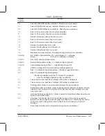
Table 8-1. EEROM Map
Address
L
i
Definition
Location
00
Value=55 if EEROM has been initialized (Read by servo processor)
01
Value=AA if EEROM has been initialized (Read by servo processor)
02
Value=5A if EEROM has been initialized (Read by servo processor)
10
Byte 0 of the number of bench-run cycles completed
11
Byte 1 of the number of bench-run cycles completed
15
Number of stepper cycles per bench-run cycle
16
Byte 0 of the total number of bench-run cycles
17
Byte 1 of the total number of bench-run cycles
18
Number of waits per bench-run cycle
19
Number of bail cycles per print in bench run
1a
Number of swaths per bench-run cycle
1b
Media-sensor correction factor. (Calculated during media-sensor calibration)
33 (bit 6)
Bit 1 (MSB) of bail-calibration (00 = not calibrated; 11 = calibrated;
status..
01 and 10 = calibration in process)
33 (bit 7)
Bit 0 (LSB) of bail-calibration status.
36 (bit 7)
Need-cartridge-alignment flag. (1 = needs cartridge alignment)
37 (bit 0)
Valid-cartridge-alignment flag. (1 = alignment performed OK)
39
PWM for carriage LED (calculated during cartridge alignment)
3d
Byte 1 of media-axis alignment distance. (Positions engagement lever.)
3e
Byte 0 of media-axis alignment distance.
Constants at address locations 3F through 4D are loaded
when the cartridge-alignment routine is performed.
3f
Value used to correct position of carriage LED relative to media axis.
40
Value used to correct position of carriage LED relative to carriage axis.
41
Cartridge offset. (Used to correct distance between the two cartridges.)
42
Bi-directional offset in columns. (Used to compensate for differences between ink-drop
trajectory when carriage is moving from left to right and that when carriage is moving
from right to left.)
4b
High-velocity factor, scaled by 64. (Used to adjust the bidirectional offset when the plot
quality is set to draft mode.)
4d
Cartridges’ first nozzles (Not all of the nozzles are used; there may be an overlap
between the two cartridges to allow for alignment. Bits 0 and 1 indicate the first nozzle
used on the right cartridge. Bits 2 and 3 indicate the first nozzle used on the left
cartridge.)
4e
Drive-roller correction factor. (Calculated during accuracy calibration.)
Summary of Contents for CalcPad 200
Page 1: ... ...
Page 3: ... ...
Page 14: ... ...
Page 15: ... ...
Page 19: ... ...
Page 22: ...2Ć4 Site Planning and Requirements C3187Ć90000 ...
Page 23: ... ...
Page 27: ... 4 1 2 3 4 5 6 mm 0 25 in 5 1 2 3 4 5 B A B A A B A B X X X ...
Page 31: ... ...
Page 33: ... ...
Page 65: ... ...
Page 139: ... ...
Page 149: ...8Ć0 8 Troubleshooting ...
Page 178: ...8Ć30 Removal and Replacement C3187Ć90000 ...
Page 179: ...9Ć0 9 Product History and Service Notes ...
Page 193: ...10Ć1 10 Parts and Diagrams ...
Page 197: ...10Ć5 Parts and Diagrams C3187Ć90000 Legs and Media Bin 1 2 3 3 4 5 6 7 1 3 4 3 3 3 3 3 8 8 ...
Page 199: ...10Ć7 Parts and Diagrams C3187Ć90000 Window Center and Bottom Covers To Carriage ...
Page 203: ...10Ć11 Parts and Diagrams C3187Ć90000 Left Endcover and Trim ...
Page 205: ...10Ć13 Parts and Diagrams C3187Ć90000 Right Endcover and Trim ...
Page 207: ...10Ć15 Parts and Diagrams C3187Ć90000 Carriage Axis Drive Left End ...
Page 209: ...10Ć17 Parts and Diagrams C3187Ć90000 Service Station 1 2 3 3 4 5 7 6 6 ...
Page 215: ...10Ć23 Parts and Diagrams C3187Ć90000 Media Drive Assemblies ...
Page 219: ...10Ć25 Parts and Diagrams C3187Ć90000 Bail and Overdrive Assemblies ...
Page 221: ...10Ć27 Parts and Diagrams C3187Ć90000 Pinch Arm Assembly ...
Page 227: ... ...
Page 231: ... ...
Page 244: ...IndexĆ04 C3087Ć90000 ...
Page 245: ... ...


