HP C8000 - Workstation - 0 MB RAM Technical Reference Manual Download Page 65

Technical Reference Guide

3–37

Installing or Replacing Parts

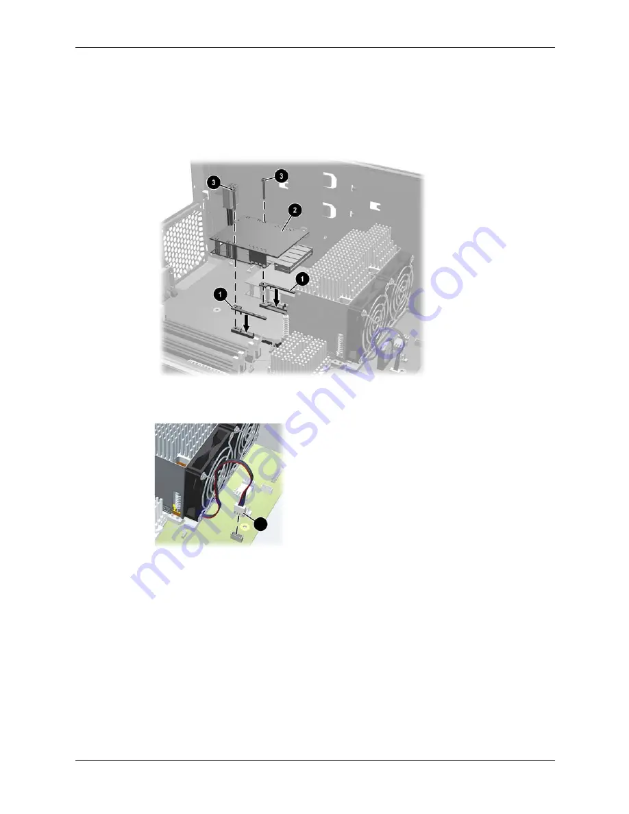
d. Insert the shims provided with the kit 

1

.

e.

Insert the processor power module into the system 

2

 and slide it into the processor until 

it stops.

f.

Tighten the two screws from the processor power module firmly using the special 
processor tool provided with the new processor 

3

.

Installing the processor power module

g. Plug in the fan connector 

1

Connecting fan connector

3. Replace the power supply (see “Replacing the Power Supply” on page 3-26) and reconnect 

all power cables.

1

Summary of Contents for C8000 - Workstation - 0 MB RAM

Page 1: ...5969 3188 Second Edition July 2004 This manual contains an overview of system specifications instructions for removing and replacing system components information on configuring your system using the included tools and interfaces and detailed troubleshooting information ...

Page 2: ...rranty of any kind including but not limited to the implied warranties of merchantability and fitness for a particular purpose and is subject to change without notice The warranties for HP products are set forth in the express limited warranty statements accompanying such products Nothing herein should be construed as constituting an additional warranty This document contains proprietary informati...

Page 3: ... HP so that they can either be recycled or disposed of in the correct way Returned batteries will be accepted free of charge ÅWARNING Metallic particulates can be especially harmful around electronic equipment This type of contamination may enter the data center environment from a variety of sources including but not limited to raised floor tiles worn air conditioning parts heating ducts rotor bru...

Page 4: ...ing your system You can access more extensive ergonomics information at www hp com ergo NOTE Recycling Your System HP has a strong commitment toward the environment Your HP system has been designed to respect the environment as much as possible HP can also take back your old system for recycling when it reaches the end of its useful life HP has a product take back program in several countries The ...

Page 5: ...stem Components 3 1 Location of Internal Components 3 2 Exploded View of Main System Components 3 3 System Board Components and Connectors 3 4 Tools and Safety 3 5 Removing and Replacing Access Panels 3 6 Removing the Main System Access Panel 3 6 Removing the Front Access Panel 3 7 Removing and Replacing Internal Components 3 8 Airflow Guide and Memory Fan 3 9 Memory Modules 3 10 PCI and AGP Cards...

Page 6: ...ve Installation Guidelines A 2 Device Classes A 3 Attach Sequence Rules by Class Priority A 3 Attach Sequence Worksheet A 4 Additional Drive Application Notes A 6 SMART A 7 Jumpers A 7 CD ROM or DVD ROM Drive A 7 SCSI Guidelines Self Monitoring Analysis and Reporting Technology SMART B 2 Cable Pin Outs Enhanced Keyboard C 1 Mouse C 1 Ethernet RJ 45 C 1 Serial Interface C 1 USB C 2 Microphone C 2 H...

Page 7: ...Technical Reference Guide 3 Contents Index ...

Page 8: ...4 Technical Reference Guide Contents ...

Page 9: ...sc c8000 Supported accessories and components at http partsurfer hp com Feature Description Processor One or two HP PA 8800 processor modules Firmware 8 MB flash EEPROM Configured using Boot Console Handler BCH Operating system HP UX 11i v1 Main memory Capacity Minimum 1 GB 2 x 512 MB Supports up to 32 GB 8 x 4 GB Type PC2100 ECC registered DDR266 DIMMs Slots Eight DIMM slots Peak bandwidth up to ...

Page 10: ...es not support HVD 80 pin SCA connector not supported IDE controller Ultra ATA 133 capable controller supporting two IDE buses and a total of four IDE devices Up to three front access optical drives or Up to two front access optical drives and two internal hard drives Graphics controller 1 AGP 8X Pro 110 slot 150 W max power including auxiliary power connector Accessory card slots Seven slots tota...

Page 11: ...keyboard and mouse HP 104 105 key keyboard available in 13 localized layouts HP three button mouse standard or scroll wheel Audio option May include PCI Audio card Front access mic and headphone connectors Line in line out microphone in on audio card Feature Description ...

Page 12: ... Minimum 20 5 kg 45 2 lb Maximum 24 7 kg 54 4 lb Dimensions Tower system Height 490 2 mm 19 3 in Depth 571 4 mm 22 5 in Chassis Width 203 2 mm 8 0 in Pedestal Width 287 0 mm 11 3 in Rack system Chassis Height 203 2 mm 8 0 in Front Panel Height 219 0 mm 8 6 in Depth 568 9 mm 22 4 in Chassis Width 424 2 mm 16 7 in Front Panel Width 482 6 mm 19 0 in Footprint tower system Space requirement rack syste...

Page 13: ...ighest current given the lowest input voltage and the maximum input power 8 7A at 100VAC 4 4A at 200VAC Input frequency 50 60 Hz Max output power2 2 Corresponds to the maximum DC power the power supply can provide to the system 700W 6 slots available at 15W slot Total of 90W 1 slot available at 110W slot Max current at 12V combined 50A Max current at 12V CPU0 15A Max current 12V CPU1 15A I 0 12V 1...

Page 14: ...atic electricity problems and cause excessive wear of the disk surface Components Power Consumption Workstation typical configuration1 410W 1399 Btu h maximum configuration2 871W 2973 Btu h Processor 130W 443 6 Btu h IDE hard disk drive with I O access 23W 78 4 Btu h IDE hard disk without I O access idle 16W 54 5 Btu h PCI card 10W to 25W 34 12 Btu h to 85 30 Btu h AGP card 110W maximum 150W possi...

Page 15: ... the product and serial numbers is on the side of the system For more information about the system LEDs see LAN LEDs Front and Rear Panel on page 4 3 Front panel tower configuration 1 System speaker 6 LAN activity LED 2 Three optical drive bays 7 Two USB connectors 3 System status LED 8 Headphone option 4 Power button 9 Microphone option 5 Disk activity LED IEEE 1394 FireWire not supported ...

Page 16: ...Front panel rack mount configuration 1 System speaker 6 LAN activity LED 2 Three optical drive bays 7 Two USB connectors 3 System status LED 8 Headphone option 4 Power button 9 Microphone option 5 Hard Disk activity LED IEEE 1394 FireWire not supported ...

Page 17: ... 1 Power cord connector 8 LAN connector and LEDs 2 Built In Self Test LED power supply LED behind ventilation holes 9 Three USB connectors 3 On board diagnostic LEDs Serial connector B 4 PCI AGP retention release Serial connector A 5 External SCSI connector option Diagnostic LEDs 6 Security cable slot Transfer of control TOC button 7 Monitor connector on graphics card ...

Page 18: ...nd LEDs 2 Built In Self Test LED power supply LED behind ventilation holes 9 Three USB connectors 3 On board diagnostic LEDs Serial connector B 4 PCI AGP retention release Serial connector A 5 External SCSI connector option Diagnostic LEDs 6 Security cable slot Transfer of control TOC button 7 Monitor connector on graphics card ...

Page 19: ...the BCH You can access the BCH through either your system s USB keyboard and graphics monitor by interrupting the normal boot process a serial console connection and terminal emulator Access via Keyboard and Graphics Monitor When you boot your system the boot process pauses and gives you 10 seconds to interrupt the normal boot process Perform the specified action to access the BCH When you are fin...

Page 20: ...ation c8000 are represented by paths in the BCH To identify the correct slot or disk drive use the following tables Accessory Card Slots IDE Drives Slot Path 1 PCI 33 MHz 32 bit half length 0 3 5 0 2 PCI 33 MHz 32 bit half length 0 3 4 0 3 AGP 8X 32 bit 0 4 0 0 4 PCI 33 MHz 64 bit 0 3 6 0 5 PCI X 66 MHz 64 bit 0 2 2 0 6 PCI X 66 MHz 64 bit 0 2 3 0 7 PCI X 133 MHz 64 bit 0 0 1 0 Drive Path Hardware...

Page 21: ...echnical Reference Guide 2 3 System Configuration SCSI Drives Network Drive Path SCSI hard drive on channel A 0 2 1 0 scsi_ID SCSI hard drive on channel B 0 2 1 1 scsi_ID Device Path Built in LAN 0 3 3 0 ...

Page 22: ...ALT CON KEY path Display or modify a path SEArch DIsplay IPL path Search for boot devices COnfiguration menu Displays or sets boot values INformation menu Displays hardware information SERvice menu Displays service commands DIsplay Redisplay the current menu HElp menu command Display help for menu or command RESET Restart the system Command Description BOot PRI ALT path Boot from a specified path ...

Page 23: ...onfiguration MOnitor LIST type Display or set the current monitor type PAth PRI ALT CON KEY path Display or change a path PoWerRestore ON OFF LAST Display or set the Power Restore Policy ResTart ON OFF Display or set the System Restart Policy SEArch DIsplay IPL path Search for boot devices SECure ON OFF Set show security mode TIme c y m d h m s Read or set the real time clock in GMT BOot PRI ALT p...

Page 24: ...ssor information FRU Display FRU information FwrVersion Display firmware version IO Display I O interface information LanAddress Display Core LAN station address MEmory Display memory information PRocessor Display processor information WArnings Display selftest warning messages BOot PRI ALT path Boot from specified path DIsplay Redisplay the current menu HElp command Display help for specified com...

Page 25: ...del string 9000 785 c8000 PROCESSOR INFORMATION HVERSION SVERSION Processor Processor Speed HVERSION SVERSION CVERSION Processor Model Model Op State 0 1000 MHz 0x088b 0x0491 3 1 Active 1 1000 MHz 0x088b 0x0491 3 1 Idle 2 1000 MHz 0x088b 0x0491 3 1 Idle 3 1000 MHz 0x088b 0x0491 3 1 Idle Central Bus Speed in MHz 200 Software ID dec 1704034802 Software ID hex 0x659181f2 Software Capability 0x01f0 ...

Page 26: ...able disable core serial ports The SCSI command is for displaying setting the SCSI controller parameters like initiator ID and speed These parameters are used by the OS device drivers to program the controller s The serial port command automatically resets the system When the serial ports are enabled the ports can be used with HP UX NOTE If the HP UX version was released prior to June 2004 the sys...

Page 27: ...t page a Select download drivers software b Enter the product name in the search field HP workstation c8000 c Select the search result d Choose the firmware release you need to download e Click the release notes for instructions on how to download unpack and install the firmware upgrade 2 Download unpack and install the firmware upgrade 3 Execute the in FwrVersion BCH command to confirm that the u...

Page 28: ...2 10 Technical Reference Guide System Configuration ...

Page 29: ...contains diagrams to help you locate system components The diagrams in this section include only the most frequently accessed components and connectors For comprehensive component and system board diagrams see the label on the inside of the main access panel Location of Internal Components page 3 2 Exploded View of Main System Components page 3 3 System Board Components and Connectors page 3 4 For...

Page 30: ...diagram identifies main system components For a comprehensive component diagram see the label on the inside of the main access panel Location of internal components 1 PCI and AGP slots 5 Optical drive bays 2 Power supply 6 Memory slots 3 Air flow guide and memory fan 7 Hard drive bays 4 CPU sockets ...

Page 31: ...el on the inside of the main access panel Exploded view of system components 1 Power supply Hard drive fan 2 CPU0 and CPU1 with power modules AGP retainer 3 Chassis fan System board 4 Airflow guide and memory fan AGP graphics card 5 Top panel Memory module 6 Optical drive Hard drive with rails 7 Chassis Front access panel rack mount 8 Front access panel tower A Main side access panel 9 Pedestal ...

Page 32: ...ntrol TOC button 23 Battery connector 33 Front panel USB connector 4 Slot 4 PCI connector 33 MHz 64 Bit 14 On board LEDs 24 Processor fan connector CPU 1 34 Hard drive fan connector 5 Slot 3 AGP Pro 8X connector 15 Chassis fan connector 25 Front control panel connector 35 SCSI A connector 6 Slot 2 PCI connector half length 33 MHz 32 Bit 16 Input power connector CPU 1 option 26 Memory fan connector...

Page 33: ...at you can lift the system or monitor safely do not try to move them without help NOTE To maintain FCC EMI Electromagnetic Interference compliance replace all covers and make sure all screws are properly seated after you replace components To prevent damage to this system observe all of the following ESD precautions while performing the system parts removal replacement procedures Work on a static ...

Page 34: ... the back of the system Always replace the cover s before turning the workstation on Removing the Main System Access Panel To remove or install most components you only need to remove the main system access panel NOTE The front system access panel only needs to be removed when removing the Front Control Module on page 3 29 or the Optical Drives CD or DVD on page 3 17 1 Unlock the panel if it is lo...

Page 35: ...1 If you have already connected and turned on the system turn off the system and disconnect all cables 2 Remove the main system access panel a Unlock the panel if it is locked 1 b Pull out on the latch to release it 2 c Rotate the panel 3 and lift it off 4 3 Remove the front system access panel a Depress the clips on the inside of the case to release the front panel 5 b Rotate the panel and lift i...

Page 36: ... 12 Optical Drives CD or DVD page 3 17 Hard Drives page 3 19 External SCSI Devices page 3 23 Power Supply page 3 25 Hard Drive and Chassis Fans page 3 27 Front Control Module page 3 29 Replacing the Processor or Installing an Additional Processor page 3 32 System Board page 3 39 System Battery page 3 41 Instructions for the following procedures are included with kits containing the parts Processor...

Page 37: ... fan 1 Turn off the system disconnect the power cable and remove the system access panel 2 Unplug the memory fan connector from the system board 1 3 Grasp the airflow guide 2 and lift it out of the system 3 Removing the airfllow guide and fan To replace the airflow guide and fan 1 Insert the airflow guide into the system and press until it snaps into place 2 Plug the memory fan connector into the ...

Page 38: ...s 1 Turn off the system disconnect all cables and remove the main access panel and airflow guide ÅWARNING To ensure that memory modules are not damaged during removal or installation power off the workstation and unplug the power cord from the AC power outlet Wait until the power supply LED page 1 7 turns off before removing or installing memory 2 Press downward and outward on the memory module re...

Page 39: ...ot backwards When the module is correctly seated the retainer clips will return to their fully upright position Snap the clips firmly into place to ensure that the DIMMs are seated properly 3 Replace the airflow guide and system access panel reconnect all cables and turn on the system 4 Check the memory configuration using the BCH Information menu page 2 6 DIMM Installation Guidelines The HP works...

Page 40: ...ace AGP graphics and PCI accessory cards Removing PCI or AGP Card 1 Turn off the system disconnect all cables and remove the main access panel 2 Remove the AGP retainer if it is blocking the card you wish to access a Press in on the release snaps on the AGP retainer 1 b Rotate the retainer outwards 2 and lift it out of the system Removing the AGP retainer ...

Page 41: ... clip 1 then rotate the clip into the open position 2 Opening the PCI AGP retainer clip 4 Remove the card a If the card is an audio card unplug the connectors attached to the front control panel see figure on page 3 29 b If the card is a full length card push the card edge stop to the side to allow the card to slide out of the guide Full length AGP or PCI card ...

Page 42: ...press the two blue release snaps on the rear panel of the system to lock it in place See figure on page 3 13 7 Replace the AGP retainer if you removed it a Insert the tab on the retainer securely into the slot on the rear edge of the system chassis 1 and rotate the retainer until it snaps into place 2 b Make sure the retainer 3 is securely holding the AGP card in place Replacing the AGP retainer 8...

Page 43: ...ry kit To install an accessory or graphics card 1 Remove the existing card or bulkhead blank that is in the slot you want to use a From the inside of the case push on the two blue release snaps at the ends of the PCI AGP retainer clip 1 then rotate the clip into the open position 2 b If the slot has a card installed remove it page 3 12 c If the slot is empty pull the filler blank out of the system...

Page 44: ...connector c If the card is a full length card the end of the card will automatically snap into place not shown 3 Close the PCI AGP retainer clip and press the two blue release snaps on the rear panel of the system to lock it in place See the figure on page 3 13 4 Replace the AGP retainer and system access panel and reconnect all cables 5 Turn on the system and check the configuration using the BCH...

Page 45: ...2 and power 3 cables from the optical drive 3 Pull outward on the lever to release the optical drives from the bay 4 Disconnecting an optical drive 4 Grasp the optical drive firmly and slide it forward to pull it out of the drive bay Removing an optical drive from tower and rack mounted systems 5 If you are not replacing the optical drive with a new drive install a blank in the drive bay opening a...

Page 46: ...If you have IDE hard drives installed one cable is used to connect the hard drives the other to connect up to two optical drives If you have SCSI hard drives installed two optical drive IDE cables are available to connect up to three optical drives To connect the IDE cable a Locate the IDE cable s connected to the secondary IDE connector on the system board 1 and route the cable s 2 to the optical...

Page 47: ...he BCH Information menu page 2 6 Hard Drives Removing a Hard Drive 1 Turn off the system disconnect all cables and remove the system access panel 2 Disconnect the hard drive IDE or SCSI cable 1 and power connector 2 3 Squeeze inward on the blue release clips located on the sides of the drive 3 Then pull outward to remove the drive from the system 4 Removing a hard drive ...

Page 48: ...from the empty bay see step 3 in figure of removing a drive on page 3 19 3 Snap the drive inside the drive tray to attach rails to the hard drive Pull outwards on the drive rails 1 then place the tray onto the drive 2 Align the pins on the tray wtih the holes on the drive and let the rails snap into place 3 Attach the rails 4 Push the drive into the bay until it snaps into place 1 Then attach the ...

Page 49: ...onnector on each cable is for the master device 3 the gray connector is for the slave device 4 Make sure the jumper on the hard drive is set to cable select CSEL not to master M or slave S See the documentation provided with your drive for help locating the jumper Install the first drive in the top bay 3 Install the second drive in the bay above the bottom bay 4 IDE hard drive locations NOTE The D...

Page 50: ...tions should include a diagram of the jumper block and jumper settings for each SCSI ID NOTE See Appendix B SCSI Guidelines for more information on configuring SCSI drives 2 Locate the SCSI cable connected to the SCSI A connector on the system board 1 and attach the cable 2 to the hard drive s 3 Install drives in bays in the following order 3 Use bay 3d for Drive 1 Use bay 3b for Drive 2 Use bay 3...

Page 51: ...Note that You can connect up to 15 devices at any SCSI ID except SCSI ID 7 which is used by the host controller The bus should be terminated as normal if you use external devices No termination is necessary if there are no devices connected SCSI IDs are set by jumpering pins on the disk drive If you are adding a SCSI hard drive to your system you may need to change the SCSI ID of the new hard driv...

Page 52: ...g the cable into the connector 1 and route as shown Installing external connector 3 Peel the release liner off of the pad on the cable and press the pad against the chassis wall 2 to secure 4 Thread the jackscrews through the rear chassis wall and into the connector 3 ...

Page 53: ...when lifting the power supply because there are cables below the power supply illustrated on the next page that must be removed before completely removing the power supply from the chassis 3 Loosen the thumbscrew that secures the power supply to the rear panel 2 4 While supporting the power supply weight with your hand 3 reach inside the system chassis and pull the lever that locks the power suppl...

Page 54: ...urpose 2 Align the tabs on the power supply with the mounting holes on the system chassis 3 Insert the new power supply into the system chassis Push the power supply up and slide it toward the back of the chassis until it snaps into place 4 Tighten in the thumbscrew that secures the power supply to the rear panel 5 Connect the remaining power supply power cables to all system components including ...

Page 55: ...ear of the system Removing the Hard Drive and Chassis Fans 1 Turn off the system disconnect the power cable and remove the system access panel and airflow guide 2 To remove the hard drive fan a Unplug the fan power cable from the system board b Push in on the snap on the side of the fan 1 Then rotate the fan towards the rear of the chassis 2 and lift it out of the system 3 Removing hard drive fan ...

Page 56: ...g the chassis fan Replacing the Hard Drive and Chassis Fans 1 Grasp the replacement fan module firmly and insert it into same location from which you removed the old fan If you are replacing the chassis fan install the push rivets 2 Re attach the fan cable 3 Replace the access panel and reconnect all cables 4 Turn the system on then check that the fans have been properly installed by verifying tha...

Page 57: ...wer button System status LED Temperature sensor Chassis intrusion switch Disk activity LED LAN activity LED Removing the Front Control Module 1 Turn off the system disconnect all cables and remove the system access panels 2 Disconnect the front control module cables Location of front control module cables and connections 1 Power 4 Audio plugged into optional PCI card Microphone a Headphone b 2 USB...

Page 58: ...e direction shown 1 b Pull the switch out of the opening 2 c Pull up on the head of the plastic push rivet and remove it then remove the sensor from the system 5 Removing the chassis intrusion switch 4 Remove the panel from the system a Use a Torx T 15 or slot screwdriver to remove the screws holding the front control module in place 1 2 3 Unscrewing the front control module ...

Page 59: ... a Insert the new switch housing into the system chassis b Insert the switch into the housing and slide in until it snaps into place 3 Replace the temperature sensor and attach it with a plastic push rivet 4 Replace the I O panel in the system and use a Torx T 15 or slot screwdriver to attach the mounting screws Replacing the front control module 5 Route the cables attached to the module to the ap...

Page 60: ... and Safety section at the beginning of this chapter before proceeding Remove the System Access Panel 1 Turn off the system and disconnect the power cable 2 Place the unit on its side with the pedestal hanging over the edge of a table 3 Remove the access panel page 3 8 Remove the Airflow Guide 1 Unplug the memory fan connector from the system board 1 2 Grasp the airflow guide 2 and lift it out of ...

Page 61: ...quence to avoid serious damage to the system 1 Remove the processor power module CPU0 is shown a Use the special processor tool included with your processor kit to remove the two screws 1 from the processor power module b Slide the processor power module towards the rear of the system until it stops then lift it out of the system Removing a processor power module ...

Page 62: ...l loosen the four screws on the processor assembly until they pop up into the released position 1 b Insert the other end of the special processor tool into the slot on the side of the heatsink and rotate the processor locking mechanism 180 degrees counter clockwise to unlock it 2 Removing the processor 3 Lift the processor out of the system ...

Page 63: ...Processor 1 Prepare the CPU socket a If you are adding a second CPU remove the plastic film covering the socket b Verify that the CPU locking mechanism is in the unlocked position Verifying unlocked position 1 The special processor tool rotates this lock 2 Unlocked 3 Locked ...

Page 64: ...crews on the processor assembly 2 NOTE If you are installing a new additional processor the second power module shown in the figure below will not be present Using the special processor tool ÄCAUTION While carefully holding the system board back against the rear of the chassis screw in the four processor screws slowly making sure to tighten all the screws evenly Tighten one pair of diagonally oppo...

Page 65: ...de it into the processor until it stops f Tighten the two screws from the processor power module firmly using the special processor tool provided with the new processor 3 Installing the processor power module g Plug in the fan connector 1 Connecting fan connector 3 Replace the power supply see Replacing the Power Supply on page 3 26 and reconnect all power cables 1 ...

Page 66: ...til it snaps into place 4 Connect the remaining power supply power cables to all system components including the hard drive s optical drive s and system board Make sure the cables are routed properly so they do not block the airflow guide or interfere with the heatsinks on the processors Replace the Airflow Guide Using the figure on page 3 38 as a guide 1 Insert the airflow guide into the system a...

Page 67: ...e and memory fan Hard drive fan DIMMs AGP retainer Accessory and graphics cards NOTE Disconnect IDE and SCSI cables from the system board Leave them attached to the hard drives and optical drives 3 Pull up on the lever on the optical drive cage see figure on page 3 17 4 and slide the optical drives forward until the rear edge of the drives is aligned with the rear edge of the drive cage 4 Depress ...

Page 68: ...s 1 Once the system board is in the system aligned with the keyhole standoffs rotate it into place 2 and slide it back toward the rear of the system until it snaps into place 3 Replacing the system board 3 Connect the system board cables and replace all components on the system board page 3 39 4 Slide the optical drives back into place 5 Replace the system access panel and reconnect the cables 6 S...

Page 69: ...tery Replacing the System Board Battery 1 Slide the battery into the battery holder The negative side should be facing out Look at the above image for correct battery orientation 2 Replace the system access panel and reconnect all cables 3 To verify that the battery has been installed correctly check the time and date settings using the BCH Time command page 2 4 You may need to reset the system ti...

Page 70: ...3 42 Technical Reference Guide Installing or Replacing Parts ...

Page 71: ...w page 4 2 Identifying and Diagnosing Hardware Problems page 4 2 BCH Error and Warning Messages page 4 12 Troubleshooting the Power Supply page 4 14 For online access to technical support information and tools go to http www hp com bizsupport Support resources include web based troubleshooting tools technical knowledge databases driver and patch downloads online communities and proactive notificat...

Page 72: ... System logs and error messages Identifying and Diagnosing Hardware Problems For basic troubleshooting tips see the HP workstation c8000 Getting Started Guide If you need further help with a hardware failure the system LEDs and logs will help you identify the problem LEDs The lights on the front and rear panels of the workstation change color and blink in different patterns to help identify specif...

Page 73: ...e system NOTE The Disk Activity LED automatically communicates with IDE and SCSI drives connected to the built in controllers To get this functionality with an SCSI or IDE controller card connect the card with an LED activity cable to the hard drive activity LED connector on the system board Refer to System Board Components and Connectors on page 3 4 for a picture showing where on the system board...

Page 74: ...le if LED one is red there is a problem with memory However if LEDs one and two are both red there is a problem with the system processor The following symbols are used in the LED tables The System Status LED on the front panel of the system indicates the state of the system Off indicates the system is off Green indicates that the system is running normally Blinking green indicates that the system...

Page 75: ...arning Categories The faults and warnings fall into the following general categories each specific error is described in detail on the following pages LED1 LED2 LED3 LED4 Category Memory Firmware System Board Fan Processor BMC System Temperature Power Unknown ...

Page 76: ... medium blink 1 0Hz LED1 LED2 LED3 LED4 Warning Solution Unknown Warnings Unknown warning Contact your HP Support Engineer Memory Warnings Mismatched memory pairs Use the memory sequence diagram in Installing Memory Modules on page 3 11 Memory load order error Use the memory sequence diagram in Installing Memory Modules on page 3 11 Can t detect memory type Contact your HP Support Engineer System ...

Page 77: ...properly PCI disk fan not functioning properly Processor Warning CPU0 temperature exceeds limit If the processor fan has failed you must replace the CPU CPU1 temperature exceeds limit Temperature Warning External air temperature too high Make sure nothing is blocking the system s airflow and locate your system in an air conditioned room Video Warning No video adapter present Install a video adapte...

Page 78: ...Solution Unknown Faults Unknown fault Contact your HP Support Engineer Memory Faults Mismatched memory pairs Use the memory sequence diagram in Installing Memory Modules on page 3 11 Uncorrectable memory error Replace memory No memory installed Install memory in matched pairs see Installing Memory Modules on page 3 11 Bad memory One or more DIMMs are bad or not seated properly Reseat the DIMMs If ...

Page 79: ...he system resets due to a problem If you cannot determine the reason for the reset contact your HP Support Engineer Cooling Unit Faults Chassis or CPU fan s not functioning properly Replace the fan that is not functioning If the processor fan has failed you must replace the CPU Memory fan not functioning properly PCI disk fan not functioning properly LED1 LED2 LED3 LED4 Fault Solution ...

Page 80: ...ceeds limit No processor detected Replace the CPU s BMC Faults BMC firmware is damaged Reflash the BMC firmware System board FRU inventory device inaccessible Replace the system board Temperature Faults External air temperature too high Make sure nothing is blocking the system s airflow and locate your system in an air conditioned room LED1 LED2 LED3 LED4 Fault Solution ...

Page 81: ...this does not work make sure the main and auxiliary cables are correctly plugged into the board If the system is still not receiving power test the power supply following the instructions in Troubleshooting the Power Supply on page 4 14 If you need to replace the power supply refer to Power Supply on page 3 25 2 BMC A few seconds after the system is plugged in this LED starts blinking which means ...

Page 82: ...ING The BMC System Event Log SEL is full ERROR The BMC BT port has failed on this system and an alternate BMC port is being used as a failover WARNING No graphics or serial consoles were found on this system WARNING No usable graphics console was found on this system The console has defaulted to a serial port Displaying PIM Information The pim command allows you to display the most recent PIM info...

Page 83: ... A on the rear panel of the workstation and to a laptop or other device with terminal emulation software NOTE If your system has a plug in serial card installed in slot 6 connect to the card s serial port instead of to Serial Port A 2 Configure the terminal emulation software with these settings Terminal emulation VT100 Wrap lines Off unchecked Baud rate 9600 Bits 8 Parity None Stop Bits 1 one Flo...

Page 84: ...test the power supply 1 Disconnect all internal power supply cables 2 Plug the power supply plug into a working electrical wall outlet 3 On the rear panel of the workstation look through the ventilation holes above the power cord connector for a green LED light If the light is visible the power supply is functional Refer to Chapter 1 in the Rear Panel section for a picture showing where the LED is...

Page 85: ...ll of the following tools as well as additional tools specific to your system MAPPER2 is an offline system configuration mapping utility It identifies and displays a list of system components including hardware modules and peripheral devices MAKODIAG is a CPU diagnostics tool MEM2 is a memory diagnostics tool To access a detailed list of tools provided on your system from the ODE Main Menu 1 Selec...

Page 86: ...cs This site includes links to an FAQ a conceptual overview and a quick reference guide to ODE Also see the section titled Diagnostics Support Tools General especially the SupportPlus Diagnostic User s Guide Chapter 3 Using the SupportPlus Media to Run Offline Diagnostics is a useful chapter for more information on what ODE is and how to run it ...

Page 87: ...ponents of the workstation or optional equipment Before beginning these procedures be sure that you are discharged of static electricity by briefly touching a grounded metal object 3 Remove the access panel 4 Remove the airflow guide and disconnect the memory fan 5 Remove the power supply 6 Locate the password header at J25 which is located at the edge of the system board between the chassis fan c...

Page 88: ...4 18 Technical Reference Guide Troubleshooting ...

Page 89: ...l drive jumper installed on the appropriate Master Drive Device 0 or Slave Drive Device 1 position Ultra ATA Cables Drives operating at speeds faster than those of the Ultra ATA 33 require an industry standard 40 pin 80 conductor Ultra ATA cable for optimal performance These cables have a maximum length of 18 inches and a maximum distance of 6 inches between the two devices for a two drive cable T...

Page 90: ...TAPI drives All drives are connected to these controllers using an industry standard 80 conductor cable Any drive attached to a controller must have a drive designation If only a single drive is connected to a controller and its jumper is in the cable select position it is designated as the Master Drive Drive Device 0 by its attachment to the Drive Device 0 cable position If two cable selected dri...

Page 91: ...eive the greatest possible bandwidth The bootable ATA hard drive should always be installed on the primary controller in the Device 0 position Attach Sequence Rules by Class Priority Drives should be attached in the sequence shown for optimum performance starting at position 1 If there are three or more devices two or more of which are hard drives two hard drives should be attached to the primary ...

Page 92: ... to determine the best drive installation sequence Two examples of how to use the worksheet are Three device installation Four device installation General Attach Sequence Rule Sequence Description 1 The lowest class drive bootable hard drive recommended 2 If only two drives the last drive goes here otherwise the lowest class of the remaining drives 3 If only three drives attach the final drive her...

Page 93: ...ction 4 3 1 the devices may be identified as Ultra ATA 133 hard drive Class 1 DVD drive Class 2 CD ROM drive Class 3 Attach Sequence Worksheet Three Device Installation Sample device name device class position number controller name device number Ultra ATA 133 hard drive 1 1 Primary 0 DVD drive 2 2 Secondary 0 CD ROM drive 3 3 Secondary 1 1 2 4 3 Primary Controller 4 1 Secondary Controller 3 2 Dev...

Page 94: ...irst before following the General Attach Sequence Rule Additional Drive Application Notes When replacing a hard drive the replacement should be of the same type Ultra ATA 33 66 100 or 133 as that being removed to retain the same level of performance When Ultra ATA and SCSI hard drives are mixed in the same system the Ultra ATA drive will become the boot drive unless the boot order is changed Attac...

Page 95: ... an impending failure or crash of the hard drive The SMART drive tracks fault prediction and failure indication parameters such as reallocated sector count spin retry count and calibration retry count If the drive determines that a failure is imminent it generates a fault alert Jumpers The specifications included below are the standard drive configurations CD ROM or DVD ROM Drive Use CSEL Slave Ma...

Page 96: ...A 8 Technical Reference Guide Ultra ATA IDE Guidelines ...

Page 97: ...nnected to the secondary external SCSI port It is not recommended to mix 50 pin SCSI devices with 68 pin SCSI devices on the same SCSI bus If it is necessary to mix these devices on the same bus care must be taken to insure integrity of the 68 pin bus ÄCAUTION Do not route data cables near the air intake to the power supply Cables routed in this manner may block the airflow and cause the workstati...

Page 98: ... an approved LVD or Multimode SCSI terminator Turn on all external SCSI devices before turning on the power to the workstation This enables the SCSI controller to recognize the external devices For additional information about installing optional SCSI devices refer to the documentation included with the device option kit Self Monitoring Analysis and Reporting Technology SMART The Self Monitoring A...

Page 99: ...fer to USB on page 2 for more information Mouse The mouse uses the USB port Refer to USB on page 2 for more information Ethernet RJ 45 Serial Interface connector pin signal 1 2 3 4 Transmit Data Transmit Data Receive Data Unused 5 6 7 8 Unused Receive Data Unused Unused connector pin signal 1 2 3 Carrier Detect Receive Data Transmit Data 4 5 6 Data Terminal Ready Signal Ground Data Set Ready 7 8 9...

Page 100: ...nd connector and icon 1 8 pin signal 1 Tip 2 Ring 3 Shield Audio Power Ground connector and icon 1 8 pin signal 1 Tip 2 Ring 3 Shield Audio_Left Audio_Right Ground connector and icon 1 8 pin signal 1 Tip 2 Ring 3 Shield Audio_In_Left Audio_In_Right Ground connector and icon 1 8 pin signal 1 Tip 2 Ring 3 Shield Audio_Out_Left Audio_Out_Right Ground ...

Page 101: ...13 3 DB14 37 DB14 4 DB15 38 DB15 5 DPB1 39 DPB1 6 GND 40 GND 7 DB0 41 DB0 8 DB1 42 DB1 9 DB2 43 DB2 10 DB3 44 DB3 11 DB4 45 DB4 12 DB5 46 DB5 13 DB6 47 DB6 14 DB7 48 DB7 15 DPB 49 DPB 16 DIFFSENSE 50 GND 17 TERMPWR 51 TERMPWR 18 TERMPWR 52 TERMPWR 19 RES 53 RES 20 ATN 54 ATN 21 GND 55 GND 22 BSY 56 BSY 23 ACK 57 ACK ...

Page 102: ...29 I O 63 I O 30 GND 64 GND 31 DB8 65 DB8 32 DB9 66 DB9 33 DB10 67 DB10 34 DB11 68 DB11 connector pin signal pin signal pin signal 1 2 3 Red Analog Green Analog Blue Analog 6 7 8 Ground Ground Ground 11 12 13 Monitor ID DDC Serial Data Horizontal Sync 4 5 Monitor ID Ground 9 10 5V DC Ground 14 15 Vertical Sync DDC Serial Clock ...

Page 103: ...TA 0 4 T M D S DATA 4 19 T M D S DATA 0 5 SHIELD 5 T M D S DATA 4 2 0 T M D S DATA 5 6 DDC CLOCK 21 T M D S DATA 5 7 DDC DATA 22 T M D S CLOCK SHIELD 8 ANALOG VERT SYNC 23 T M D S CLOCK 9 T M D S DATA 1 24 T M D S CLOCK 10 T M D S DATA 1 11 T M D S DATA 1 3 SHIELD C1 ANALOG RED 12 T M D S DATA 3 C2 ANALOG GREEN 13 T M D S DATA 3 C3 ANALOG BLUE 14 5V POWER C4 ANALOG HORZ SYNC 15 GND C5 ANALOG GROUN...

Page 104: ...3 4 5 Reset Ground DD7 DD8 DD6 15 16 17 18 19 DD1 DD14 DD0 DD15 Ground 29 30 31 32 33 DMAK Ground INTRQ IOCS16 DA1 6 7 8 9 10 DD9 DD5 DD10 DD4 DD11 20 21 22 23 24 Key DMARQ Ground DIOW Ground 34 35 36 37 38 PDIAG cable detect DA0 DA2 CS1FX CS3FX 11 12 13 14 DD3 DD12 DD2 DD13 25 26 27 28 DIOR Ground IORDY CSEL 39 40 DASP Ground ...

Page 105: ...A0 44 45 46 47 48 Reserved VCC 1 5 TRDY STOP PME Reserved VCC 1 5 DEVSEL Vddq PERR 16 17 18 19 20 VCC 1 5 SBA3 SB_STB Ground SBA5 VCC 1 5 SBA2 SB_STB Ground SBA4 49 50 51 52 53 Ground PAR AD15 Vddq AD13 Ground SERR C BE1 Vddq AD14 21 22 23 24 25 SBA7 Reserved Ground Reserved VCC 1 5 SBA6 Reserved Ground 1 5 Vaux VCC 1 5 54 55 56 57 58 AD11 Ground AD9 C BE0 Vddq AD12 Ground AD10 AD8 Vddq 26 27 28 2...

Page 106: ... VCC1 5 Ground VCC1 5 Ground Ground VCC1 5 VCC1 5 VCC1 5 VCC1 5 VCC1 5 Reserved Reserved VCC12 VCC12 VCC12 Reserved Reserved Ground Ground Ground 6 7 8 9 10 Ground Ground Ground Reserved Reserved VCC1 5 VCC1 5 VCC1 5 PRSNT2 PRSNT1 VCC12 VCC12 VCC12 VCC12 VCC12 Ground Ground Ground Ground Ground 11 12 13 14 VCC12 VCC12 VCC12 VCC12 Ground Ground Ground Ground ...

Page 107: ...ROUND 18 BLACK 4 V5 18 RED 5 GROUND 18 BLACK 6 V5 18 RED 7 GROUND 18 BLACK 8 PWR_OK 22 GRAY 9 5VSB 18 PURPLE 10 V12 IO 18 YELLOW 11 V12 IO 18 YELLOW 12 V3P3 18 ORANGE 13 V3P3 18 ORANGE 14 V12N 18 BLUE 15 GROUND 18 BLACK 16 PS_ON_L 22 GREEN 17 GROUND 18 BLACK 18 GROUND 18 BLACK 19 GROUND 18 BLACK 20 V3P3 RSENSE 22 BROWN 21 V5 18 RED 22 V5 V5 RSENSE 18 22 RED RED 23 V5 18 RED 24 GROUND 18 BLACK ...

Page 108: ... is available Hard Drive Activity Connector No illustration available connector position output awg wire color P2 SSi 6 PIN LENGTH 520 1 V3P3 18 ORANGE 2 V3P3 18 ORANGE 3 V12 IO 18 YELLOW 4 GROUND 18 BLACK 5 GROUND 18 BLACK 6 V12 IO 18 YELLOW pin signal 1 NC 2 PCIACT_L 3 PCIACT_L 4 NC ...

Page 109: ...2V 3 Ground TMS 4 TDO TDI 5 5V 5V 6 5V INTA 7 INTB INTC 8 INTD 5V 9 PRSNT1 Reserved 10 Reserved 3 3V 11 PRSNT2 Reserved 12 CONNECTOR KEY 3 3 volt key 13 CONNECTOR KEY 3 3 volt key 14 Reserved 3 3Vaux 15 Ground RST 16 CLK 3 3V 17 Ground GNT 18 REQ Ground 19 PME 3 3V 20 AD 31 AD 30 21 AD 29 3 3V 22 Ground AD 28 A1 B1 A62 B62 A94 B94 3 3 volt Key ...

Page 110: ... AD 19 Ground 31 3 3V AD 18 32 AD 17 AD 16 33 C BE 2 3 3V 34 Ground FRAME 35 IRDY Ground 36 3 3V TRDY 37 DEVSEL Ground 38 Ground STOP 39 LOCK 3 3V 40 PERR Reserved 41 3 3V Reserved 42 SERR Ground 43 3 3V PAR 44 C BE 1 AD 15 45 AD 14 3 3V 46 Ground AD 13 47 AD 12 AD 11 48 AD 10 Ground 49 M66EN AD 09 50 Ground Ground 5 volt key 51 Ground Ground 5 volt key ...

Page 111: ...ACK64 REQ64 61 5V 5V 62 5V 5V 32 bit connector end CONNECT OR KEY 64 bit spacer CONNECT OR KEY 64 bit spacer 63 Reserved Ground 64 bit connector start 64 Ground C BE 7 65 C BE 6 C BE 5 66 C BE 4 3 3V 67 Ground PAR64 68 AD 63 AD 62 69 AD 61 Ground 70 AD 60 3 3V 71 AD 59 AD 58 72 AD 57 Ground 73 Ground AD 56 74 AD 55 AD 54 75 AD 53 3 3V 76 Ground AD 52 77 AD 51 AD 50 ...

Page 112: ...79 3 3V AD 48 80 AD 47 AD 46 81 AD 45 Ground 82 Ground AD 44 83 AD 43 AD 42 84 AD 41 3 3V 85 Ground AD 40 86 AD 39 AD 38 87 AD 37 Ground 88 3 3V AD 36 89 AD 35 AD 34 90 AD 33 Ground 91 Ground AD 32 92 Reserved Reserved 93 Reserved Ground 94 Ground Reserved 64 bit ...

Page 113: ...3 10 drive device designation A 1 replacement type A 6 DVD ROM jumpers A 7 E environmental specificaions 1 6 E Support 4 2 Ethernet RJ 45 connector pin assignments C 1 F fan 3 27 faults and warnings 4 5 warnings 4 7 faults 4 5 4 8 firmware 1 1 2 1 faults 4 8 faults and warnings 4 5 firmware upgrades 2 9 FPL log 4 12 front access panel 1 1 3 7 front panel rack mount 1 8 tower 1 7 G graphics trouble...

Page 114: ...nstalling additional 3 32 model 1 1 removing 3 33 warnings 4 7 R rear panel rack mount 1 10 tower 1 9 S safety i iii 3 5 SCSI 3 19 3 22 SCSI controller 1 2 SCSI drives connector pin assignments C 3 SEL log 4 12 serial interface connector pin assignments C 1 serial ports description 1 2 set up 2 1 SMART A 7 software diagnostic tools 4 2 system board 3 39 faults 4 9 4 11 faults and warnings 4 5 warn...

Reviews: