


Bermuda User’s Manual
21
2. HARDWARE SETUP
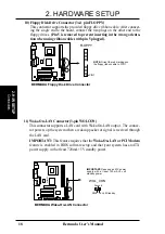
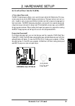
16) USB Headers (10-2 pin HP_USB)
If more USB port connectors are needed, an onboard HP_USB header is avail-
able for two additional USB port connectors. Connect the USB headers to an
optional 2-port USB connector set and mount the bracket to an open slot on your
chassis.
0
1
0
1
BERMUDA
BERMUDA USB Port
1
2
11
12
GND
GND
GND
GND
USBP
–
USBP
–
USBP+
USBP+
USB Power
USB Power
HP-USB
Connectors
2. H/W SETUP
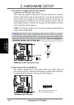
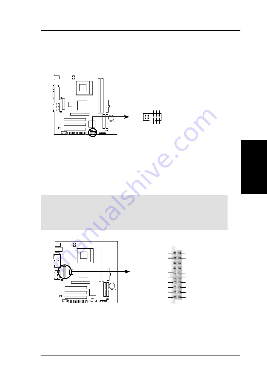
17) ATX Power Supply Connector (20-pin block ATXPWR)
This connector attaches to an ATX power supply. The plug from the power supply
will only insert in one orientation because of the different hole sizes. Find the
proper orientation and push down firmly making sure that the pins are aligned.
IMPORTANT:
Make sure that your ATX power supply can supply at least 10mA
on the +5-volt standby lead (+5VSB). You may experience difficulty in power-
ing ON your system if your power supply cannot support the load. For Wake-
On-LAN support, your ATX power supply must supply at least 720mA +5VSB.
0
1
0
1
BERMUDA
BERMUDA ATX Power Connector
ATX
+3.3Volts
-12.0Volts
Ground
Power Supply On
Ground
Ground
Ground
-5.0 Volts
+5.0 Volts
+5.0 Volts
Power Good
+12.0Volts
+3.3 Volts
+3.3 Volts
Ground
+5.0 Volts
Ground
+5.0 Volts
Ground
+5V Standby


