


72
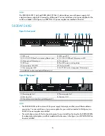
5800-24G-PoE+/5800-24G-PoE+TAA
Figure 82
Front panel
(1) 10/100/1000Base-T auto-sensing Ethernet port
(2) 10/100/1000Base-T Ethernet port LED
(3) SFP+ port LED
(4) Console port
(5) USB port
(6) Seven-segment LED
(7) Port mode LED
(8) System status LED (SYS)
(9) RPS status LED (RPS)
(10) Interface card status LED (SLOT1)
(11) Port LED mode switching button
(12) SFP+ port
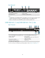
Figure 83
Rear panel
(1) RPS receptacle
(2) AC-input power receptacle
(3) Grounding screw
(4) Interface card slot
NOTE:
The 5800-24G-PoE+ and 5800-24G-PoE+TAA switches come with the expansion interface card slot
covered by a filler panel. In this figure, an LSW1SP4P0 interface card is installed in the slot.


