background image

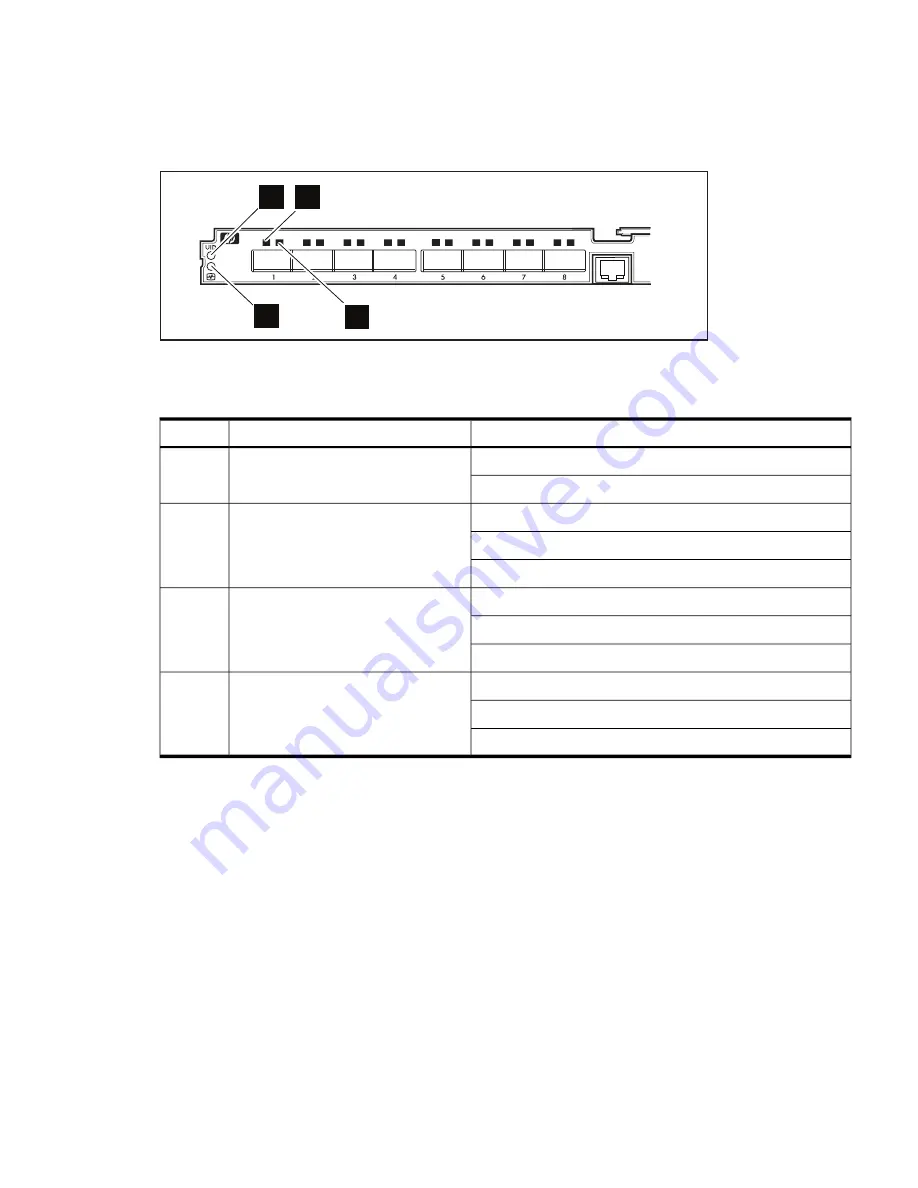
1.6 HP BLc 4X DDR InfiniBand Gen 2 Switch LEDs

Figure 1-4

shows the LEDs and

Table 1-1

describes the LEDS in the HP BLc 4X DDR InfiniBand

Gen 2 Switch.

Figure 1-4 HP BLc 4X DDR InfiniBand Gen 2 Switch LEDs

2

1

3

4

Table 1-1

describes the callouts shown in

Figure 1-4

:

Table 1-1 HP BLc 4X DDR InfiniBand Gen 2 Switch Descriptions and Status

Status

Description

Item

Blue = Activated

Unit ID LED

1

Off = Deactivated

Green = Normal

Internal health LED

2

Amber = Component degraded

Off = Power

Green = Physical link established

Physical link LED

3

Green flashing = Physical link error

Off = No physical link established

Amber = Logical link established

Logical link / Activity LED

4

Amber flashing = Logical link with activity

1

Off = No logical link established

1

The logical link activity LED flashes with greater frequency as network activity increases.

1.6 HP BLc 4X DDR InfiniBand Gen 2 Switch LEDs

9

Summary of Contents for 489183-B21 - InfiniBand DDR Switch

Page 1: ...HP BLc 4X DDR InfiniBand Gen 2 Switch Installation Guide for HP c Class BladeSystems HP Part Number 5992 5296 Published October 2008 Edition 1 02 ...

Page 2: ...re set forth in the express warranty statements accompanying such products and services Nothing herein should be construed as constituting an additional warranty HP shall not be liable for technical or editorial errors or omissions contained herein Printed in the U K InfiniBand is a trademark of the InfiniBand Trade Association Gore is a trademark of W L Gore Associates Inc ...

Page 3: ...4X DDR InfiniBand Gen 2 Switch into the HP BladeSystem Enclosure 12 2 2 Installing InfiniBand Cables in the HP BLc 4X DDR InfiniBand Gen 2 Switch 12 2 2 1 Removing an InfiniBand Cable from the HP BLc 4X DDR InfiniBand Gen 2 Switch 14 2 3 InfiniBand Cable Management Bracket 14 2 4 InfiniBand Subnet Management 15 3 Removing the HP BLc 4X DDR InfiniBand Gen 2 Switch for Service 17 4 Regulatory Compli...

Page 4: ...BladeSystem c7000 Enclosure Interconnect Module Bay 11 2 2 Installing the HP BLc 4X DDR InfiniBand Switch into a c7000 Enclosure 12 2 3 QSFP InfiniBand DDR QDR Cable 13 2 4 Align the InfiniBand Cable with the HP BLc 4X DDR InfiniBand Gen 2 Switch Port 13 2 5 InfiniBand Cable Installed in Port 1 of the HP BLc 4X DDR InfiniBand Gen 2 Switch 14 4 1 EU Declaration of Conformity Markings 20 4 2 Japanes...

Page 5: ...List of Tables 1 1 HP BLc 4X DDR InfiniBand Gen 2 Switch Descriptions and Status 9 5 ...

Page 6: ...6 ...

Page 7: ...ocument Warranty documentation Note This kit does not include a subnet manager the InfiniBand cables or the cable management bracket You must install a subnet manager on a host node or install an internally managed InfiniBand interconnect to manage the InfiniBand fabric You must also order the InfiniBand cables and the cable management bracket separately Figure 1 1 HP BLc 4X DDR InfiniBand Gen 2 S...

Page 8: ...nk ports on HP 4X DDR InfiniBand Gen 2 Switch An external subnet manager not included in the HP 4X DDR InfiniBand Gen 2 Switch manages the topology for the InfiniBand fabric 1 5 HP BLc 4X DDR InfiniBand Gen 2 Switch Connector Bays Figure 1 3 shows the Quad Small Form factor Pluggable QSFP connector bays on the front of the HP BLc 4X DDR InfiniBand Gen 2 Switch Figure 1 3 HP BLc 4X DDR InfiniBand G...

Page 9: ...s Status Description Item Blue Activated Unit ID LED 1 Off Deactivated Green Normal Internal health LED 2 Amber Component degraded Off Power Green Physical link established Physical link LED 3 Green flashing Physical link error Off No physical link established Amber Logical link established Logical link Activity LED 4 Amber flashing Logical link with activity 1 Off No logical link established 1 Th...

Page 10: ...10 ...

Page 11: ... operation for proper cooling and for EMI emissions control 2 1 1 Prepare the Interconnect Module Bay in the HP BladeSystem c7000 Enclosure To prepare the interconnect module bay in the HP BladeSystem c7000 enclosure follow these steps 1 Remove any devices or blanks 2 To remove the divider press the divider release button see callout 1 in Figure 2 1 and slide the divider out of the interconnect mo...

Page 12: ... it is in the locked position 2 2 Installing InfiniBand Cables in the HP BLc 4X DDR InfiniBand Gen 2 Switch Figure 2 3 shows an InfiniBand cable with a QSFP connector used with the HP BLc 4X DDR InfiniBand Gen 2 Switch QSFP connector to QSFP connector InfiniBand DDR QDR cables are used to connect multiple HP BLc 4X DDR InfiniBand Gen 2 Switches together For example you might connect two or more HP...

Page 13: ...in the HP BLc 4X DDR InfiniBand Gen 2 Switch To install an InfiniBand cable in the HP BLc 4X DDR InfiniBand Gen 2 Switch follow these steps 1 Align the InfiniBand cable QSFP connector see callout 1 in Figure 2 4 with the HP BLc 4X DDR InfiniBand Gen 2 Switch port see callout 2 in Figure 2 4 2 Insert the QSFP connector into the HP BLc 4X DDR InfiniBand Gen 2 Switch port see callout 1 in Figure 2 5 ...

Page 14: ... connector while using your other hand to remove the connector from the switch port To completely remove the cable it might be necessary to remove a releasable cable tie on the HP c Class blade cable management bracket If it is necessary to remove a releasable cable tie from the cable management bracket to fully release a QSFP InfiniBand connector from the switch reverse the installation procedure...

Page 15: ...ch A subnet manager can be host based which must be installed and run on a host node connected to the InfiniBand fabric You can also use a switch based subnet manager when certain managed switches are incorporated into the InfiniBand fabric For more information about InfiniBand subnet management refer to the InfiniBand interconnect documentation that came with your system or cluster Also refer to ...

Page 16: ...16 ...

Page 17: ...nd radius It might be necessary to loosen the releasable cable ties enough to remove the cable from the switch HP recommends that you do not remove the cables from the releasable cable ties on the c Class cable management bracket 2 Remove the cable management bracket from the 10K rack s rear rails but do not remove the cables from the bracket 3 Press the switch blade handle release button and slid...

Page 18: ...18 ...

Page 19: ...on of this equipment in a residential area is likely to cause harmful interference in which case the user will be required to correct the interference at personal expense 4 3 Modifications The FCC requires the user to be notified that any changes or modifications made to this device that are not expressly approved by Hewlett Packard Company may void the user s authority to operate the equipment 4 ...

Page 20: ...ation of Conformity Markings Hewlett Packard GmbH HQ TRE Herrenberger Strasse 140 71034 Boeblingen Germany 4 7 Japanese Notice Figure 4 2 Japanese Notice 4 8 Korean Notice Figure 4 3 Korean Notice 20 Regulatory Compliance ...

Page 21: ...21 ...

Page 22: ... 5992 5296 Printed in the U K ...

Reviews: