background image

Page 12 


Installer’s Information Manual 

Exposure to the following substances in the combustion air 
supply may also require outdoor air for combustion: 

??

Aerosols  

??

Permanent wave solutions  

??

Chlorinated waxes, bleaches a nd cleaners  

??

Cat litter 

??

Chlorine-based swimming pool chemicals  

??

Cleaning solvents  

??

Paint removers and varnishes  

??

Adhesives 

??

Anti-static fabric softeners  

??

Most refrigerants 


WARNING

:  Combustion air that contains chlorine, 

fluorine, bromine or  iodine could cause corrosion in heat 
exchanger and may result in nausea or death by 
asphyxiation. 

UNCONFINED SPACE INSTALLATION (non-direct 
vent) 

The National Fuel Gas Code, ANSI Z223.1/NFPA 54 and 
CAN/CGA B149 Installation Codes do not require that you 
m ake special provisions for combustion and ventilation air 
when furnace is in an "unconfined space" and building is 
not of "unusually tight construction." 

??

"Unconfined spaces" have a volume of at least 50 
cubic feet per 1000 Btu per hour combined input rating 
of all appliances installed in the space.  For example: a 
100,000 Btu/hr furnace and a 40,000 Btu/hr water 
heater would require a volume of at least 140,000 X 50 
÷ 1,000 or 7,000 cubic feet. 

??

"Unusually tight construction" means windows and 
doors are either tight fitting or are sealed construction 
and that walls are covered with a continuous, sealed 
vapor barrier and drywall or similar materials having 
sealed joints. 

If you meet the volume requirements for unconfined space, 
the building is not of unusually  tight construction and there 
are no airborne contaminants, as listed above, you may 
install this fu rnace without making special provisions for 
combustion and ventilation air.  Otherwise, follow the 
instructions for "confined space installation" below or direct 
vent the furnace using two pipes. 

CONFINED SPACE INSTALLATION (non-direct 
vent) 

A non-direct vented furnace installed in a confined space 
must take combustion and ventilation air from an 
unconfined space within the building or from outdoors.  
However, if the building is of unusually tight construction all 
combustion air must come from outdoors.  Also, if retu rn air 
is taken directly from a hallway or space next to fu rnace 
that communicates with fu rnace spaces, all combustion air 
must come from outdoors . 


WARNING

:  You must provide permanent air 

openings to a confined fu rnace installation space from 
another area as described below.  Failure to do so could 
cause inadequate combustion and ventilation air and may 
result in nausea or death  by asphyxiation. 

ALL COMBUSTION AND VENTILATION AIR FROM 
INSIDE THE BUILDING 

The confined furnace space must be provided with two 
permanent openings to an additional room of sufficient 
volume so that the combined volumes of the spaces meet 
the criteria above for an unconfined space not of unusually 
tight construction.  The total input of all gas appliances 
within the combined space must be considered in making 
this determination. 

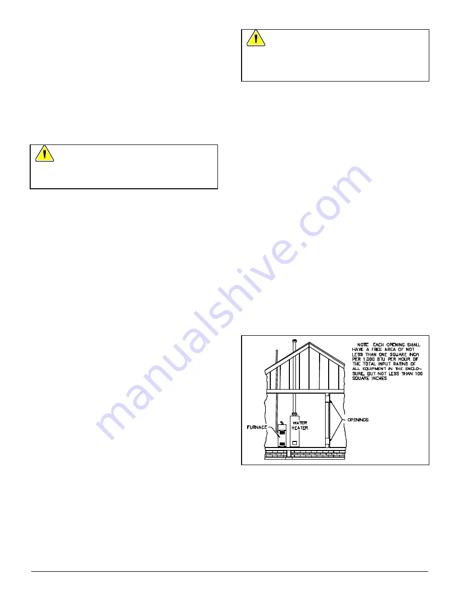
Each opening must have minimum free area of one square 
inch per 1,000 Btu per hour of the total combined input 
rating of all gas appliances within the confined fu rnace 
space, but not less than 100 square inches.  One opening 
must be within 12 inches of the top and one opening within 
12 inches of the bottom of the fu rnace space.  Th e shortest 
side of each air opening must be at least 3 inches long.  
See Figure 9. 

For example: 

??

A 90,000 Btu/hr furnace and a 40,000 Btu/hr water 
heater would require free area openings of 130,000 ÷ 
1,000 or 130 square inches. 

??

A 54,000 Btu/hr furnace and a 40,000 Btu/hr water 
heater would require the minimum free area openings 
of 100 square inches. 


Figure 9.  Confined Space, All Air From Inside The Building. 

ALL COMBUSTION AND VENTILATION AIR FROM 
OUTDOORS 

The furnace space must  be provided with two permanent 
air openings communicating directly, or by ducts, with the 
outdoors or spaces that freely access the outdoors.  Well-
ventilated attics or crawl spaces usually satisfy this 
requirement.  These openings will give fu rnace free access 
to fresh air for combustion and ventilation. 

Summary of Contents for 422690

Page 1: ... give you the documents listed on opposite side You should immediately read the User s Information Manual for important safety information to keep y ou and your family safe Keep these as long as you keep your furnace Pass them on to future furnace purchasers or users If any of the documents are missing or illegible contact your installer or furnace manufacturer for replacement Throughout this manu...

Page 2: ... in this manual Must is mandatory Should is advisory WARNING Read and follow the safety rules in this section and throughout this manual Failure to do so could cause improper furnace operation resulting in damage injury or death Rule 1 Use only gas approved for use in this furnace as indicated on furnace rating plate Use only natural gas in furnaces designed for natural gas Use only propane LP gas...

Page 3: ...clearance for service WARNING Some insulating materials are combustible When a furnace is installed in an attic or other insulated space keep all insulating materials at least 12 inches away from furnace and combustion air inlet Failure to do so could cause a fire You may install furnace on non combustible flooring or on wood flooring WARNING Do not install furnace on carpeting tile or other combu...

Page 4: ...0 2 0 2 OR 3 90 000 1 2 17 1 2 15 3 4 15 15 16 1 0 0 2 0 2 OR 3 90 000 3 4 20 1 2 18 3 4 18 15 16 1 0 0 2 0 2 OR 3 108 000 3 4 23 1 2 21 3 4 21 15 16 1 0 0 2 0 3 126 000 3 4 23 1 2 21 3 4 21 15 16 1 0 0 2 0 3 See Furnace Rating Plate located on blower door These are furnace dimensions See Sections 9 and 10 for proper ductwork and floor opening dimensions Certified for installation on wood flooring...

Page 5: ...gs that may hold water Support horizontal portions of vent pipe every 5 feet 3 feet for SDR 21 or SDR 26 pipe Protect vent from freezing Long runs of vent pipe installed in an unconditioned space may require insulation to prevent freezing of condensate Furnace can be vented from either left or right side See Figure 2 As shipped furnace is setup for venting through the left side Right side venting ...

Page 6: ...peration while any other appliances connected to the venting system are not in operation 1 Seal any unused openings in the venting system 2 Inspect the venting system for proper size and horizontal pitch as required in the National Fuel Gas Code ANSI Z223 1 NFPA 54 or the CAN CGA B149 Installation Codes Determine that there is no blockage or restriction leakage corrosion and other deficiencies whi...

Page 7: ...126 000 Btu hr model may need a high altitude pressure switch when installed at elevations between 3000 and 4000 feet Above 4000 feet this model requires a high altitude switch for all installations All furnace models require the high altitude pressure switch when installed at elevations above 6000 feet The high altitude pressure switch is supplied with the LP Conversion Kit 4226000 and the Natura...

Page 8: ...0 15 108 000 3 40 40 40 40 40 40 40 40 See Note 2 below 126 000 3 40 40 40 40 35 30 25 20 54 000 2 40 40 40 40 40 40 40 40 72 000 2 21 18 14 11 72 000 3 40 40 40 40 40 40 40 40 5001 6000 90 000 3 40 40 40 40 40 40 40 40 108 000 3 40 35 30 25 20 15 10 108 000 3 40 40 40 40 40 40 40 40 See Note 2 below 126 000 3 40 40 40 40 35 30 25 20 54 000 2 40 40 40 40 40 40 40 40 72 000 2 40 40 40 40 36 32 28 2...

Page 9: ... Attach a combustion air pipe to combustion air inlet collar on top of furnace Use rubber coupling and hose clamps supplied with furnace See Figure 5 Figure 5 Combustion Air Pipe Connection to Furnace for Direct Vent NON DIRECT VENTING INSTRUCTIONS one pipe system DETERMINING VENT LENGTH See Table 2 for maximum vent pipe length Include any termination elbows when determining maximum allowable vent...

Page 10: ... 60 55 50 108 000 3 85 80 75 70 65 60 55 50 See Note 2 126 000 3 62 57 52 47 42 37 32 27 54 000 2 43 40 37 33 30 27 24 20 72 000 2 21 18 14 11 72 000 3 150 150 150 150 150 150 150 150 5001 6000 90 000 3 70 65 60 55 50 45 40 35 108 000 3 85 80 75 70 65 60 55 50 See Note 2 126 000 3 62 57 52 47 42 37 32 27 54 000 2 110 106 104 100 96 92 88 84 72 000 2 50 46 43 40 36 32 29 25 72 000 3 150 150 150 150...

Page 11: ...requirements of all gas appliances in the building You must also allow for reduction of air available for combustion and ventilation caused by exhaust fans range hoods and fireplaces Sufficient air must be provided to ensure there will not be a negative pressure in furnace room or space In addition there must be a positive seal between furnace and return air duct to avoid pulling air from burner a...

Page 12: ...om an unconfined space within the building or from outdoors However if the building is of unusually tight construction all combustion air must come from outdoors Also if returnair is taken directly from a hallway or space next to furnace that communicates with furnace spaces all combustion air must come from outdoors WARNING You must provide permanent air openings to a confined furnace installatio...

Page 13: ...0 108 000 27 6 113 000 126 000 31 5 7 153 000 144 000 36 7 153 000 When communicating with the outdoors through vertical ducts openings and ducts must have a minimum free area of one square inch per 4 000 Btu per hour of total combined input rating of all gas appliances within furnace space See Figure 11 and Table 3 Figure 11 All Air Through Vertical Ducts From Spaces That Freely Access The Outdoo...

Page 14: ...piping is large enough for all appliances connected to it to operate at once without lowering gas supply pressure Failure to do so could cause lighting or burning problems on any of the appliances Always use a pipe thread compound that is resistant to propane LP gas solvent action Sparingly apply thread compound to all joints on male threads only starting two threads from the end INSTALLATION Gas ...

Page 15: ...cal Code CSA C22 1 WARNING Failure to provide a proper electrical ground could result in electric shock or fire Provide furnace with its own separate electrical circuit and means of circuit protection Furnace must have an electrical disconnect switch located at furnace WARNING Failure to provide the above shut off means could result in electrical shock or fire Use electrical wiring that meets curr...

Page 16: ...Page 16 Installer s Information Manual Figure 15 Furnace Wiring Diagram ...

Page 17: ... is de energized Main blower remains energized for 60 seconds CONSTANT FAN MODE Thermostat calls for constant fan R and G terminals connected Fan Timer energizes main blower on heating speed A call for cooling mode while in constant fan mode causes main blower to change from heating to cooling speed Sixty seconds after the call for cooling mode ends main blower changes back to heating speed A call...

Page 18: ...o bottom return air opening Bottom closure panel is available from manufacturer See Table 5 for bottom closure part numbers Table 5 Bottom Closure Part Numbers GAS INPUT Btu hr MOTOR HORSE POWER BOTTOM CLOSURE PART NUMBER 54 000 1 3 4045901 72 000 90 000 1 2 4045901 72 000 90 000 3 4 4045902 108 000 126 000 3 4 4045903 GAS INPUT and MOTOR HP can be found on furnace rating plate WARNING Failure to ...

Page 19: ...25 X 1 72 000 90 000 108 000 126 000 3 4 20 X 25 X 1 20 X 25 X 1 GAS INPUT and MOTOR HP can be found on furnace rating plate FILTER CABINETS Use a bottom filter cabinet side filter cabinet or return air filter grille Field fabricated filter cabinets should allow 1 inch spacing between filter and furnace Placing a field supplied filter directly against furnace bottom or side will decrease airflow a...

Page 20: ...lowly open equipment shut off valve in gas supply line just ahead of furnace 7 Slowly open 1 8 NPT manual shut off valve leading to manometer 8 Turn on all gas appliances attached to gas supply line 9 With furnace operating read gas supply pressure on manometer Natural gas supply pressure must be between 5 and 7 inches W C Propane gas LP supply pressure must be between 11 and 13 inches W C 10 If g...

Page 21: ...place burner access panel using three screws removed in step 2 SECTION 14 CHECKING GAS INPUT RATE It is the installer s responsibility to see that the Btu input rate of the furnace is properly adjusted Under firing could cause inadequate heat primary heat exchanger corrosion and or ignition problems Over firing could cause sooting flame impingement and or overheating of heat exchanger WARNING Fail...

Page 22: ...ustment 3 Start furnace following Operating Instructions on front door 4 Let furnace warm up for 6 minutes 5 Adjust manifold pressure to 10 0 inches W C 0 3 inches W C See Section 13 Manifold Pressure Adjustment WARNING Do not set Propane LP manifold pressure at 11 0 inches W C It could cause heat exchanger failure NOTE NOx reducing screens must be removed from each tube of California NOx furnaces...

Page 23: ...al power and gas before changing orifices Follow this procedure 1 Turn off electricity at electrical disconnect switch next to furnace 2 Turn off equipment shut off valve in gas supply line just ahead of furnace 3 Remove three screws holding burner access panel in place Remove burner access panel 4 Starting with burner farthest from gas control remove main burner screws and main burners Note how b...

Page 24: ...0 1 2 35 65 ML YEL 72 000 3 4 30 60 ML YEL 90 000 1 2 45 75 MH BLUE 90 000 3 4 35 65 MH BLUE 108 000 3 4 35 65 MH BLUE 126 000 3 4 45 75 MH BLUE Gas Input and Motor HP can be found on rating plate These are factory settings Table 10 Cooling Speed Selection GAS MOTOR AIR CONDITIONING TONNAGE INPUT SIZE AT 0 5 INCHES WC Btu hr HP 1 5 2 2 5 3 3 5 4 5 54 000 1 3 LO ML MH HI 72 000 1 2 LO ML HI 72 000 ...

Page 25: ...should be set according to Table 9 Cooling speed should be set to meet cooling equipment requirements See Table 10 for cooling airflow capacities at 0 5 inch W C 6 Place one thermometer in supply air plenum approximately 2 feet from furnace Locate thermometer tip in center of plenum to ensure proper temperature measurement 7 Place second thermometer in return air duct approximately 2 feet from fur...

Page 26: ...itches located near 24 volt terminal strip on Fan Timer 2 Determine switch settings for desired heating blower off delay See Figure 23 3 Set switches on Fan Timer using a small screwdriver NOTE Cooling blower off delay is fixed at 60 seconds and is not adjustable Figure 23 Heating Blower Off Delay SECTION 23 MAINTAINING FURNACE IN GOOD WORKING ORDER WARNING Use replacement parts listed in parts li...

Page 27: ...Industries name Choose from the T87 round w subbase T834 heating and cooling or the T8699 Chronotherm III available in white only PROPANE CONVERSION KIT BELOW 6 000 ft Includes propane regulator spring kit propane pilot orifice and main burner orifices HIGH ALTITUDE PROPANE CONVERSION KIT ABOVE 6 000 ft Includes propane regulator spring kit propane pilot orifice main burner orifices and high altit...

Reviews: