background image

Expansion Module 

HP IP Console Switch User Guide 

3-5


HP CONFIDENTIAL


Writer: Amy L. Laffitte File Name: d-ch3 Expansion Module.doc 

Codename: Eagle Part Number: 263924-002 Last Saved On: 3/18/03 10:13 AM 

Performing a Rail-Mount Installation 

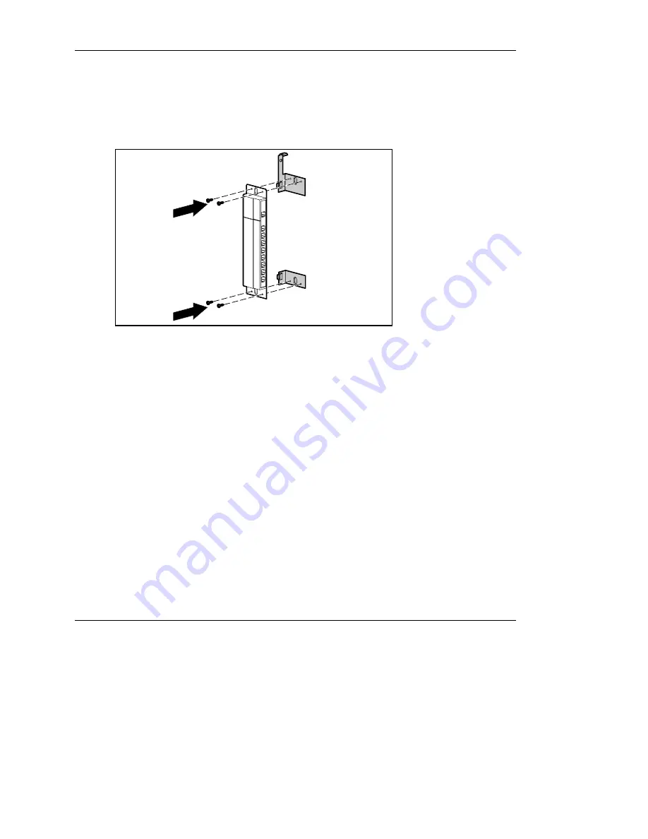
To rail mount an Expansion Module to the rack: 

1. 

Remove screws securing the side-mounting brackets to the Expansion Module. 


Figure 3-4:  Removing screws 

Summary of Contents for 263924-002

Page 1: ... CONFIDENTIAL Writer Amy L Laffitte File Name a frnt doc Codename Eagle Part Number 263924 002 Last Saved On 4 1 03 9 56 AM HP IP Console Switch User Guide June 2003 Second Edition Part Number 263924 002 ...

Page 2: ...nmental Protection Agency Hewlett Packard Company shall not be liable for technical or editorial errors or omissions contained herein The information in this document is provided as is without warranty of any kind and is subject to change without notice The warranties for HP products are set forth in the express limited warranty statements accompanying such products Nothing herein should be constr...

Page 3: ...ortant Safety Information ix Symbols on Equipment ix Rack Stability xi Symbols in Text xi Related Documents xii Getting Help xii Technical Support xii HP Website xiii Authorized Reseller xiii Reader s Comments xiii Chapter 1 Overview Features 1 2 Benefits 1 3 IP Console Switch Components 1 4 Chapter 2 Installing the IP Console Switch Installation Checklist 2 2 Kit Contents 2 2 Required Tool 2 2 Op...

Page 4: ... Installing the Expansion Module into the IP Console Switch System 3 8 Chapter 4 Interface Adapters Features 4 1 Connecting an Interface Adapter to the IP Console Switch System 4 3 Chapter 5 Cascade Console Switches Connecting Cascade Switches to the IP Console Switch System 5 3 Cascading 2 x 8 Compaq Legacy Console Switches into the IP Console Switch System 5 3 Chapter 6 Local Port Operation View...

Page 5: ...Servers 6 20 Accessing Broadcast Dialog Box 6 21 Broadcasting Selected Servers 6 22 Activating Broadcasting 6 22 Setting up a Scan Pattern 6 22 Accessing the Scan Dialog Box 6 23 Adding Servers to the Scan List 6 24 Removing Servers from the Scan List 6 24 Starting Scan Mode 6 25 Stopping Scan Mode 6 25 Setting Local Console Switch Security 6 25 Accessing the Security Dialog Box 6 26 Changing the ...

Page 6: ...TFTP for Windows 7 4 Updating the IP Console Switch 7 6 Updating the IP Console Switch Hardware 7 6 Updating the IP Console Switch through the IP Console Viewer 7 12 Establishing LAN Connections 7 16 Upgrading FLASH Firmware 7 16 Analyzing FLASH Failures 7 18 Upgrading Interface Adapter Firmware 7 19 Chapter 8 Troubleshooting Appendix A Regulatory Compliance Notices Regulatory Compliance Series Nu...

Page 7: ...t Saved On 4 1 03 9 56 AM Mouse Compliance Statement A 4 European Union Notice A 5 Japanese Notice A 6 BSMI Notice A 6 Appendix B Electrostatic Discharge Preventing Electrostatic Damage B 1 Grounding Methods To Prevent Electrostatic Damage B 2 Appendix C Power Cord Set Requirements General Requirements C 1 Country Specific Requirements C 2 Index ...

Page 8: ...onsole Switches HP assumes you are qualified in the servicing of equipment and trained in recognizing hazards in products with hazardous energy levels Important Safety Information Before installing this product read the Important Safety Information document included with this product Symbols on Equipment The following symbols may be placed on equipment to indicate the presence of potentially hazar...

Page 9: ...work interface connection WARNING To reduce the risk of electric shock fire or damage to the equipment do not plug telephone or telecommunications connectors into this receptacle This symbol indicates the presence of a hot surface or hot component If this surface is touched the potential for injury exists WARNING To reduce the risk of injury from a hot component allow the surface to cool before to...

Page 10: ...ne component is extended at a time A rack could become unstable if more than one component is extended for any reason Symbols in Text These symbols can be found in the text of this guide They have the following meanings WARNING Text set off in this manner indicates that failure to follow directions in the warning could result in bodily harm or loss of life CAUTION Text set off in this manner indic...

Page 11: ...pport In North America call the HP Technical Support Phone Center at 1 800 652 6672 This service is available 24 hours a day 7 days a week For continuous quality improvement calls may be recorded or monitored Outside North America call the nearest HP Technical Support Phone Center Telephone numbers for worldwide Technical Support Centers are listed on the HP website www hp com Be sure to have the ...

Page 12: ...te at www hp com For product specific information refer to the following website http h18004 www1 hp com products servers proliantstorage rack options kvm index console html Authorized Reseller For the name of your nearest authorized reseller In the United States call 1 800 345 1518 In Canada call 1 800 263 5868 Elsewhere see the HP website for locations and telephone numbers Reader s Comments HP ...

Page 13: ...with RJ 45 connections and provides optimal digital video performance with a maximum resolution of 1280 x 1024 at 75 Hz up to 15 24 meters 50 feet and a maximum resolution of 800 x 640 at 60 Hz up to 30 48 meters 100 feet The IP Console Switch works over standard LAN connections providing access across a 100Base T Ethernet connection for one or up to three simultaneous IP users depending on the mo...

Page 14: ...le over serial port and NIC Compatibility with HP video monitors and hotkeys on all HP keyboards including the HP TFT5600RKM Field terminable CAT5 cables Near real time mouse cursor speed Multiple language support through programmable ROM SoftPaq English Spanish French Dutch German Italian and Japanese Support for 10 100 NIC ports Application clients that manage 25 IP Console Switches with 512 tar...

Page 15: ...litation of KVM access in higher server density environments because of an increase in the number of ports available KVM access through network connection No special software or drivers are required on the attached computers including the host Users access the unit and all attached systems through Ethernet from a user running the IP Console Viewer User can be located anywhere a valid network conne...

Page 16: ...15 16 100 240V 1 0A 50 60 Hz T 2A 250 VAC CAUTION For continued protection against risk of fire replace only with same type and rating of fuse 1 2 3 4 5 6 7 8 9 Figure 1 1 IP Console Switch components Item Description 1 Power connector 2 Power switch 3 Activity indicator 4 Serial download connector 5 Monitor connector for local user 6 Keyboard connector for local user 7 Mouse connector for local u...

Page 17: ... 2 3 4 5 6 7 8 9 10 11 12 13 14 15 16 100 240V 1 0A 50 60 Hz T 2A 250 VAC CAUTION For continued protection against risk of fire replace only with same type and rating of fuse 1 A 1 A 1 2 3 4 5 6 7 Figure 1 2 Example of an IP Console Switch configuration Item Description 1 CPU 2 IP Console Switch 3 Interface Adapter 4 Network 5 Keyboard connector 6 Mouse connector 7 Video connector ...

Page 18: ...uthorized access to the console switch through IP connection For more information refer to the HP IP Console Switch Software Guide included on the Rack Products Documentation CD NOTE The analog port does not require the IP Console Viewer software for operation The analog port uses the on screen display OSD For more information refer to Chapter 6 The IP Console Switch system uses Ethernet networkin...

Page 19: ...M Installation Checklist Before installing the IP Console Switch refer to the following lists to be sure that all of the listed components were received Kit Contents IP Console Switch Power cords Rack mounting kit Download serial cable Documentation kit Firmware software CD CAT5 crossover cable Required Tool You need a Phillips screwdriver Optional Items Expansion Module Interface Adapter UTP CAT5...

Page 20: ...alling the console switch and other components in the rack cabinet if not already installed stabilize the rack in a permanent location Install your equipment starting at the bottom of the rack cabinet then work to the top Avoid uneven loading or overloading of rack cabinets NOTE Prior to installing the IP Console Switch into the rack connect the console switch to a power source using the power cor...

Page 21: ...alling doc Codename Eagle Part Number 263924 002 Last Saved On 3 31 03 3 13 PM Using Side Mount 0U Installation Type A To side mount the IP Console Switch 1 Attach the side mounting brackets to the console switch using two screws on each side 1 2 3 4 5 6 7 8 9 10 11 12 13 14 15 16 Figure 2 1 Attaching the side mounting brackets ...

Page 22: ...924 002 Last Saved On 3 31 03 3 13 PM 2 Slide the tabs on the side mounting brackets into the same U location on each side of the rack 1 2 3 4 5 6 7 8 9 10 11 12 13 14 15 16 Figure 2 2 Sliding the tabs into the rack 3 Secure the console switch to the rack frame using two screws on each side 1 2 3 4 5 6 7 8 9 10 11 12 13 14 15 16 Figure 2 3 Securing the console switch ...

Page 23: ...Codename Eagle Part Number 263924 002 Last Saved On 3 31 03 3 13 PM Type B 1 Attach the side mounting brackets to the console switch using two screws on each side 2 Slide the tabs on the side mounting brackets into the same U location on each side of the rack 1 2 3 4 5 6 7 8 9 10 11 12 13 14 15 16 Figure 2 4 Sliding the tabs into the rack ...

Page 24: ... Installing doc Codename Eagle Part Number 263924 002 Last Saved On 3 31 03 3 13 PM 3 Insert four cage nuts into the rack frame in the location of the side mounting bracket holes 1 2 3 4 5 6 7 8 9 10 11 12 13 14 15 16 Figure 2 5 Inserting cage nuts 4 Secure the console switch to the rack frame using two screws on each side ...

Page 25: ...1U component such as the 1U Keyboard Drawer Rack Option Kit additional rack space is not required making it a 0U installation To install the IP Console Switch in the rear of the rack 1 Attach the slide rail brackets to the console switch using two screws on each slide 1 2 3 4 5 6 7 8 9 10 11 12 13 14 15 16 100 24 0V 1 0A 50 60 Hz T 2A 250 VAC CAUTI ON For continu ed protect ion against risk of fir...

Page 26: ...eady installed in the rack 1 2 3 4 5 6 7 8 9 10 11 12 13 14 15 16 100 2 40V 1 0A 50 60 Hz T 2A 250 VAC CAUT ION For contin ued protec tion agains t risk of fire replac e only with same type and rating of fuse Figure 2 7 Sliding the console switch into the rack 4 Secure the slide rail brackets to the rear of the rack using two screws on each side 1 2 3 4 5 6 7 8 9 10 11 12 13 14 15 16 100 2 40V 1 0...

Page 27: ...plate that was shipped with the component to mark the location of the mounting hardware a Push back the tabs marked Õ on the top of the template and place them in the correct holes in the mounting rails Figure 2 9 Measuring with the rack template b Match up the hole pattern indicated on the sides of the template with the hole pattern on the mounting rails c Measuring from the top of the component ...

Page 28: ...ing doc Codename Eagle Part Number 263924 002 Last Saved On 3 31 03 3 13 PM 3 Install two cage nuts into the holes marked by the template at the rear of the rack Figure 2 10 Installing cage nuts 4 Loosely attach the wing nuts 1 and extend the adjustable rail mounting brackets to the desired length 2 1 2 Figure 2 11 Adjusting rails ...

Page 29: ... 03 3 13 PM 5 Tighten the wing nuts slightly to stabilize the adjustable rails during installation 6 Insert an adjustable rail into the rack and hook the tabs into the appropriate holes at the rear of the rack aligning the screws holes at the front of the rack 7 Secure the rear of the adjustable rail using one screw for each cage nut previously installed Figure 2 12 Securing the adjustable rail ...

Page 30: ... rail to the rack using two screws for each rail Figure 2 13 Securing the adjustable rail 9 Slide the console switch into the adjustable rails and secure it to the rear of the rack using one screw on each side 1 2 3 4 5 6 7 8 9 10 11 12 13 14 15 16 100 2 40V 1 0A 50 60 Hz T 2A 250 VAC CAUT ION For contin ued protec tion agains t risk of fire replac e only with same type and rating of fuse Figure 2...

Page 31: ...ch Hardware To configure the IP Console Switch hardware 1 Connect one end of a serial cable to an available COM port on the server that is to be viewed locally from the IP Console Switch 2 Connect the other end of the serial cable to the serial port on the IP Console Switch 3 Plug the supplied power cord in to the rear of the IP Console Switch and then in to a valid power source 4 Power on the IP ...

Page 32: ...and None for Flow Control then click OK The HyperTerminal auto connects to the console switch e Press the Enter key to access the console switch option menu To configure Minicom IMPORTANT Minicom is a utility that is loaded during the installation of Red Hat 7 2 and 7 3 However if you do not select the option to install the Linux Utilities during the operating system installation you are not able ...

Page 33: ...sure that the Change which setting menu is configured as follows A Serial Device dev ttyS0 B Lockfile Location var lock C Callin Program D Callout Program E Bps Par Bits 9600 8N1 F Hardware Flow Control No G Software Flow Control No g Press the Enter key to return to the Configuration menu Scroll down to the Save setup as dfl option and press the Enter key h Scroll down the Configuration menu to t...

Page 34: ...r 263924 002 Last Saved On 3 31 03 3 13 PM i From the Linux Red Hat 7 2 and 7 3 command prompt enter Minicom As soon as a connection is established the Main menu for the IP Console Switch is displayed Follow the on screen options to configure the IP Console Switch The IPViewer HyperTerminal menu with six options is displayed Figure 2 16 IPViewer HyperTerminal menu ...

Page 35: ...out relying on the auto negotiate feature After you enter your selection you return to the Network Configuration menu 8 Select Option 2 to specify a static or BootP IP address Use a static IP address for ease of configuration If you are using a BootP address configure your BootP server to provide an IP address to the console switch omit step 9 and continue to the next procedure 9 Select Option 3 t...

Page 36: ...D For Windows operating systems default drivers 1 From the desktop select Start Settings Control Panel and double click the Mouse icon 2 Select the Motion tab 3 For Windows NT set Pointer Speed to Slow and the Acceleration setting to None or For Windows 2000 set the Speed setting to 50 default and the Acceleration setting to None or For Windows XP set the set the Speed setting to 50 default and th...

Page 37: ...the OSD at the local analog station and input all server names You can also customize the OSD as well as access the IP Console Switch from the analog station For detailed instructions on OSD setup and configuration refer to Chapter 6 in this guide 2 After you install the IP Console Viewer on each digital station launch the IP Console Viewer and click Add Console Switch to add the new IP Console Sw...

Page 38: ...ach port increasing the total number of accessible servers to 128 Features The features of the Expansion Module include Connection to an IP Console Switch through a single UTP CAT5 cable Connection to each Interface Adapter through a single UTP CAT5 cable Connections for eight Interface Adapters An active KVM connection between one IP Console Switch port and one Interface Adapter at a time No exte...

Page 39: ...2 3 4 5 6 7 8 9 10 11 12 13 14 15 16 100 2 40V 1 0A 50 60 Hz T 2A 250VAC CAUTION For continued protection against risk of fire replace only with same type and rating of fuse 1 2 3 4 5 6 Figure 3 1 Example of an IP Console Switch configuration with an Expansion Module Item Description 1 IP Console Switch 2 Expansion Module 3 Interface Adapter 4 Video connector 5 Keyboard connector 6 Mouse connector...

Page 40: ...on Module doc Codename Eagle Part Number 263924 002 Last Saved On 3 18 03 10 13 AM Installing the Expansion Module Hardware Performing a Side Mount Installation To side mount an Expansion Module to the rack 1 Slide the tabs on the side mounting brackets into the rack frame Figure 3 2 Sliding the tabs into the rack ...

Page 41: ... Writer Amy L Laffitte File Name d ch3 Expansion Module doc Codename Eagle Part Number 263924 002 Last Saved On 3 18 03 10 13 AM 2 Secure the Expansion Module to the rack frame using one self tapping screw for the bottom side mounting bracket Figure 3 3 Inserting screw ...

Page 42: ... File Name d ch3 Expansion Module doc Codename Eagle Part Number 263924 002 Last Saved On 3 18 03 10 13 AM Performing a Rail Mount Installation To rail mount an Expansion Module to the rack 1 Remove screws securing the side mounting brackets to the Expansion Module Figure 3 4 Removing screws ...

Page 43: ...dule doc Codename Eagle Part Number 263924 002 Last Saved On 3 18 03 10 13 AM 2 Position the Expansion Module and insert two cage nuts into the rack frame where the mounting bracket holes are located 1 Secure the Expansion Module to the rack frame using two M 6 screws 2 2 2 1 1 Figure 3 5 Installing the Expansion Module ...

Page 44: ...3 10 13 AM Performing a Velcro Mount Installation To Velcro mount an Expansion Module to the rack 1 Determine the location for the Expansion Module 2 Remove the protective strip 1 from the Velcro and attach it to the Expansion Module 3 Remove the protective strip 1 from the other side of the Velcro and attach it to the rack frame 2 2 1 1 Figure 3 6 Velcro mounting the Expansion Module ...

Page 45: ...ystem 1 Mount the Expansion Module into the rack using one of the previously described methods 2 Locate up to nine UTP CAT5 cables 3 Connect one end of a UTP CAT5 cable to the desired port on the rear panel of the IP Console Switch 4 Attach the other end of the UTP CAT5 cable to the IN port on the Expansion Module 5 Connect one end of another UTP CAT5 cable to the OUT port on the Expansion Module ...

Page 46: ...CAT5 cables to standard VGA video and PS 2 connections Features The features of an Interface Adapter include Connection to an IP Console Switch through a single UTP CAT5 cable Reduction of cable bulk No external power required Compatible with Compaq legacy console switches Keep Alive functionality enabling continuous mouse and keyboard data activity to attached servers even when the IP Console Swi...

Page 47: ...18 03 10 32 AM 1 2 3 4 5 6 7 8 9 10 11 12 13 14 15 16 100 2 40V 1 0A 50 60 Hz T 2A 250VAC CAUT ION For contin ued protec tion against risk of fire replac e only with same type and rating of fuse 2 1 3 4 5 Figure 4 1 IP Console Switch configuration with an Interface Adapter Item Description 1 IP Console Switch 2 Interface Adapter 3 Video connector 4 Keyboard connector 5 Mouse connector ...

Page 48: ...m To connect an Interface Adapter to each server 1 Locate the Interface Adapter 2 Attach the appropriate color coded connectors on the Interface Adapter to the KVM ports on the server that connects to the IP Console Switch 3 Connect one end of a UTP CAT5 cable to the desired port on the rear panel of the IP Console Switch 4 Connect the other end of the UTP CAT5 cable to the RJ 45 connector on the ...

Page 49: ...2 x 8 PN 400338 001 291 B 31 2 x 8 48VDC PN 400542 B21 IMPORTANT All Compaq legacy console switches must be upgraded with SoftPaq firmware version 2 1 0 or later If you do not upgrade the legacy console switches the IP Console Switch system will not recognize them The IP Console Switch system supports only one level of cascading To be sure that the equipment performs at optimum levels follow prope...

Page 50: ... 03 10 52 AM 1 2 3 4 5 6 7 8 9 10 11 12 13 14 15 16 100 240 V 1 0A 50 60 Hz T 2A 250VAC CAUTIO N Forcontinue dprotectio nagainst riskoffire replace onlywithsame typeandrating offuse 1 6 2 3 4 5 Figure 5 1 Example of an IP Console Switch system with tiering Item Description 1 IP Console Switch 2 Interface Adapter 3 Video connector 4 Keyboard connector 5 Mouse connector 6 Compaq legacy console switc...

Page 51: ...le to connect your console switch to the Interface Adapter for your console switch 2 Attach one end of a UTP CAT5 cable to the RJ 45 connector on the Interface Adapter 3 Connect the other end of the UTP CAT5 cable to the desired port on the rear panel of the console switch 4 Attach the keyboard monitor and mouse connectors of the Interface Adapter to a user port on your cascaded console switch 5 C...

Page 52: ...nables the user to configure the system Viewing and Selecting Ports and Servers Use the OSD Main dialog box to view configure and control servers in the IP Console Switch system You can also view your servers by name port or by the unique EID embedded in each Interface Adapter When the OSD is first launched an OSD generated port list is displayed by default The Port column indicates the port to wh...

Page 53: ...umber 263924 002 Last Saved On 3 31 03 3 17 PM Accessing the Main Dialog Box To access the Main dialog box Press the Print Scrn key The Main dialog box is displayed NOTE You can also press the Ctrl key twice within one second to launch the OSD You can use this key sequence in any place you see Print Scrn throughout this user guide Figure 6 1 Main dialog box ...

Page 54: ...s indicated in the right column of the Main dialog box Table 6 1 OSD Status Symbols Item Description green circle Interface Adapter is connected or powered on Interface Adapter is not connected or is powered off Interface Adapter is tiered to another console switch and is not connected or is powered off Interface Adapter is tiered to another console switch and is connected or powered on yellow cir...

Page 55: ...ned to the Interface Adapter or If the display order of the server list is by port the Port button is selected enter the Port number and press the Enter key or If the display order of the server list is by Name or EID number the Name or EID button is selected enter the first few letters of the Name of the server or the EID number to establish it as unique and then press the Enter key Selecting Pre...

Page 56: ...nt Scrn key The Main dialog box is displayed 2 Click Setup The Setup dialog box is displayed 3 Click Menu The Menu dialog box is displayed 4 For Screen Delay Time enter the number of seconds of delay desired before the Main dialog box displays after the Print Scrn key is pressed 5 Click OK Soft Switching Servers To soft switch servers 1 To select a server press the Print Scrn key If the display or...

Page 57: ...urrent dialog box without saving changes and returns to the previous dialog box In the Main dialog box it closes the OSD and returns to the selected server In a message box it closes the pop up box and returns to the current dialog box Alt When used in combination with the other keys opens dialog boxes selects options and executes actions Alt X Closes the current dialog box and returns to the prev...

Page 58: ...crn Pause Immediately activates the screen saver mode and prevents access to that particular console if it is password protected Up Down Arrows Moves the cursor from line to line Right Left Arrows Moves the cursor between columns When editing a text box these keys move the cursor within the column Page Up Page Down Pages up and down through Name and Port lists Home End Moves the cursor to the top ...

Page 59: ...ng between numerically by Port or EID number and alphabetically by name Changes the Delay Time before the Main dialog box displays after pressing the Print Scrn key Flag Changes the display timing color and location of the status flag Broadcast Simultaneously controls multiple servers through keyboard and mouse actions Scan Sets up custom scan patterns for up to 16 servers Security Sets password t...

Page 60: ... File Name g ch6 Local Port Operation doc Codename Eagle Part Number 263924 002 Last Saved On 3 31 03 3 17 PM Accessing the Setup Menu To access the Setup menu 1 Press the Print Scrn key The Main dialog box is displayed 2 Click Setup The Setup dialog box is displayed Figure 6 2 Setup dialog box ...

Page 61: ...e Interface Adapter or server to another switch port the IP Console Switch recognizes the names and configurations NOTE If a server is powered off its respective Interface Adapter is not displayed in the Names list Accessing the Names Dialog Box To access the Names dialog box 1 Press the Print Scrn key The Main dialog box is displayed 2 Click Setup Names The Names dialog box is displayed NOTE If t...

Page 62: ...agle Part Number 263924 002 Last Saved On 3 31 03 3 17 PM Assigning Names to Servers To assign names to servers 1 Press the Print Scrn key The Main dialog box is displayed 2 Click Setup Names The Names dialog box is displayed 3 Select the name or port number and click Modify The Name Modify dialog box is displayed Figure 6 4 Name Modify dialog box ...

Page 63: ...9 spacebar and hyphen 5 Click OK to transfer the new name to the Names dialog box Changes made to the Names dialog box are not saved until you click OK 6 Repeat steps 3 through 5 for each server in the system 7 Click OK in the Names dialog box to save your changes or Click X to exit or press the ESC key to exit the dialog box without saving changes Assigning Device Types While the console switch a...

Page 64: ...Scrn key The Main dialog box is displayed 2 Click Setup Devices The Devices dialog box is displayed NOTE The Modify button is only available if a configurable switch is selected Figure 6 5 Devices dialog box When the IP Console Switch discovers a cascaded switch the port numbering changes to accommodate each server under that switch For example if the switch is connected to port 2 the switch port ...

Page 65: ...e Devices dialog box select the Port number 2 Click Modify The Device Modify dialog box is displayed 3 Choose the number of ports supported by the cascaded console switch 4 Click OK 5 Repeat steps 2 through 4 for each port the user wants to assign a device type 6 Click OK in the Devices dialog box to save settings NOTE Changes made in the Device Modify dialog box are not saved until you click OK i...

Page 66: ...ervers switch connection mode and a time to delay display of the OSD after pressing the Print Scrn key can be changed The display order setting alters how servers display in several screens including the Main Devices and Broadcast dialog boxes Accessing the Menu Dialog Box To access the Menu dialog box 1 Press the Print Scrn key The Main dialog box is displayed 2 Click Setup The Setup dialog box i...

Page 67: ...elect EID to display servers numerically by Interface Adapter ID number or Select Port to display servers numerically by port number 2 Click OK Setting Screen Delay Time Setting a time to delay the display of the OSD enables you to complete a soft switch without displaying the OSD To perform a soft switch see the Soft Switching section in this chapter To set the Screen Delay Time for the OSD 1 Fro...

Page 68: ... shows the Name or EID number of the selected server or the status of a particular port Use the Flag dialog box to change the flag display by server Name or EID number or to change the flag color opacity display time and location on the desktop Table 6 4 OSD Status Flags Flag Description Flag type by Name Flag type by EID number Flag indicating that the user has been disconnected from all systems ...

Page 69: ... Operation doc Codename Eagle Part Number 263924 002 Last Saved On 3 31 03 3 17 PM Accessing the Flag Dialog Box To access the Flag dialog box 1 Press the Print Scrn key The Main dialog box is displayed 2 Click Setup The Setup dialog box is displayed 3 Click Flag The Flag dialog box is displayed Figure 6 8 Flag dialog box ...

Page 70: ...lag for only five seconds after soft switching 3 Select a flag color in Display Color 4 In the Display Mode select Opaque for a solid color flag or select Transparent to see the desktop through the flag 5 Position the status flag on the desktop a Click Set Position to gain access to the Position Flag screen b Left click and hold the title bar and drag to the desired location c Right click to retur...

Page 71: ...ion Broadcasting Keystrokes The keyboard statistics must be identical for all servers receiving a broadcast to interpret keystrokes identically Specifically the Caps Lock and Num Lock modes must be the same on all keyboards While the switch attempts to send keystrokes to the selected servers simultaneously some servers can inhibit and thereby delay the transmission Broadcasting Mouse Movements For...

Page 72: ...Local Port Operation doc Codename Eagle Part Number 263924 002 Last Saved On 3 31 03 3 17 PM Accessing Broadcast Dialog Box To access the Broadcast dialog box 1 Press the Print Scrn key The Main dialog box is displayed 2 Click Setup Broadcast The Broadcast dialog box is displayed Figure 6 10 Broadcast dialog box ...

Page 73: ...ress the Esc key to return to the Main dialog box 3 From the Commands menu select the Broadcast Enable checkbox to activate broadcasting 4 From the user station enter the information and or perform the mouse movements you want to broadcast Activating Broadcasting To activate or deactivate broadcasting from the Commands menu select or deselect the Broadcast Enable checkbox Setting up a Scan Pattern...

Page 74: ...Name g ch6 Local Port Operation doc Codename Eagle Part Number 263924 002 Last Saved On 3 31 03 3 17 PM Accessing the Scan Dialog Box To access the Scan dialog box 1 Press the Print Scrn key The Main dialog box is displayed 2 Click Setup Scan The Scan dialog box is displayed Figure 6 11 Scan dialog box ...

Page 75: ...e click a server name or port or Press the Alt key plus the number of the server you want to scan You can select up to 16 servers 2 In the Scan Time box enter the number of seconds from 3 to 99 before the scan moves to the next server in the sequence 3 Click OK NOTE If the user removes a server from the Device Modify dialog box later the change can affect a custom scan pattern Removing Servers fro...

Page 76: ...e stops at the currently selected server or Deselect Scan Enable in the Commands menu Any active connections on the local port are disconnected Setting Local Console Switch Security The OSD enables you to set security on the local port consoles You can establish a screen saver mode that engages after the console remains unused for a user definable time delay When engaged the console remains locked...

Page 77: ... doc Codename Eagle Part Number 263924 002 Last Saved On 3 31 03 3 17 PM Accessing the Security Dialog Box To access the Security dialog box 1 Press the Print Scrn key The Main dialog box is displayed 2 Click Setup The Setup dialog box is displayed 3 Click Security The Security dialog box is displayed Figure 6 12 Security dialog box ...

Page 78: ...d can consist of A Z 0 9 spacebar and hyphen 3 In the Repeat field reenter the password and press the Enter key 4 Click OK to change the password Setting Password Protection To password protect your local console 1 From the Security dialog box set your password as described in the previous procedure 2 Select Enable Screen Saver 3 Enter the number of minutes for Time Delay from 1 to 99 to delay act...

Page 79: ...Password dialog box is displayed Enter the password then click OK 2 In the Security dialog box click the New field and press the Enter key or Double click the New field leave the New field blank and press the Enter key 3 Click the Repeat field and press the Enter key or Double click the Repeat field leave the Repeat field blank and press the Enter key 4 Click OK if you want to eliminate the passwo...

Page 80: ...Energy Star 5 Optional Click Test to activate the screen saver test which lasts 10 seconds then returns you to the Security dialog box 6 Click OK NOTE After activation of the screen saver mode disconnects the user from a server no server is selected The status flag displays Free Exiting Screen Saver Mode To exit the screen saver mode press any key or move the mouse The Main dialog box is displayed...

Page 81: ...se Broadcast Enable Begin broadcasting to your servers Configure a server list for broadcasting under the Setup dialog box Scan Enable Begin scanning your servers Set up a list for scanning in the Setup dialog box User Status View and disconnect users Run Diagnostics Validate the integrity of your system including memory firmware cyclic redundant checks CRC comm interfaces switch controller local ...

Page 82: ...me g ch6 Local Port Operation doc Codename Eagle Part Number 263924 002 Last Saved On 3 31 03 3 17 PM Accessing the Commands Menu To access the Commands menu 1 Press the Print Screen key The Main dialog box is displayed 2 Click Commands The Commands dialog box is displayed Figure 6 13 Commands dialog box ...

Page 83: ...isplayed However either the server name or Interface Adapter ID number to which the user is connected can also be displayed The User Status dialog box displays only the number of users the system supports If there are no users are currently connected to a channel the fields are blank and the server indicates it is free Viewing Current User Connections To view current user connections 1 Press the P...

Page 84: ...e g ch6 Local Port Operation doc Codename Eagle Part Number 263924 002 Last Saved On 3 31 03 3 17 PM Disconnecting a User To disconnect a user 1 Press the Print Scrn key The Main dialog box is displayed 2 Click Commands User Status The User Status dialog box is displayed Figure 6 14 User Status dialog box ...

Page 85: ...he Disconnect dialog box is displayed Figure 6 15 Disconnect dialog box 4 Click OK to disconnect the user and return to the User Status dialog box or Click X to exit or press the Esc key to exit the dialog box without disconnecting a user NOTE If the User Status dialog box has changed since it was last displayed the mouse cursor becomes an hourglass as the list automatically updates No mouse or ke...

Page 86: ...ostics command This command checks the main board functions subsystems memory intra board communications console switch control and the video channels for each system controller When you select Run Diagnostics you receive a warning indicating that all users remote and local will be disconnected Click OK to confirm and begin the test Running Diagnostics Test To run diagnostics tests 1 Press the Pri...

Page 87: ...Operation doc Codename Eagle Part Number 263924 002 Last Saved On 3 31 03 3 17 PM 3 Click Run Diagnostics A warning message is displayed indicating that all users will be disconnected Figure 6 16 Diagnostics Warning 4 Click OK to begin or Click X or press the Esc key to exit the dialog box without running a diagnostic test ...

Page 88: ...Test Description Memory Test Reports the condition of the main board RAM This indicator displays the results of the memory tests performed at system reboot Firmware CRC Validates the current firmware images stored in the system s FLASH by comparing a CRC value on each image and comparing those results to the expected values Comm Interfaces Verifies the intra board communication subsystems are acce...

Page 89: ...n Verifies the LAN connection is accessible and functional by verifying the link controller is responsive and monitoring the network traffic If the link controller is responsive the test passed indictor is displayed If the link controller is non responsive the test failed indictor is displayed If the link controller is functional but no network traffic has been received an indictor is displayed On...

Page 90: ...led test is indicated by a red X and the LAN connection has a third indicator which indicates that the LAN connection is functional but no network traffic has been received The test is complete when the last test s symbol displays 7 Optional If you have any offline Interface Adapters you can click the Clear button to remove them from the list 8 Optional If you have any suspect Interface Adapters y...

Page 91: ...ommunication reestablished between the server and the console switch functionality is restored to the user NOTE This function is for Microsoft Windows based computers only Resetting the PS 2 on a computer running any other operating system might require that you reboot that computer To reset the PS 2 mouse values 1 Press the Print Scrn key The Main dialog box is displayed 2 Click Commands The Comm...

Page 92: ...IP Console Viewer versions as well as keyboard and mouse information for the currently selected server For optimum performance keep your firmware current NOTE Provide the application version number Figure 6 20 when communicating with HP customer service centers To display version information 1 Click Version in the Commands dialog box The Version dialog box is displayed The top half of the box list...

Page 93: ...d On 3 31 03 3 17 PM 2 Click Digital to view the IP Console Viewer versions The Digital Version dialog box is displayed The top section identifies the digitizer subsystem versions The center section identifies the current network settings NOTE Provide the application version number Figure 6 20 when communicating with HP customer service centers Figure 6 21 Digital Version dialog box ...

Page 94: ...File Name g ch6 Local Port Operation doc Codename Eagle Part Number 263924 002 Last Saved On 3 31 03 3 17 PM or Click IA to access the IA Selection dialog box to view individual Interface Adapter cable version information The IA Selection dialog box is displayed Figure 6 22 IA Selection dialog box ...

Page 95: ...n doc Codename Eagle Part Number 263924 002 Last Saved On 3 31 03 3 17 PM 3 To view the selected Interface Adapter cable click Version The IA Version dialog box is displayed NOTE Provide the application version number Figure 6 19 when communicating with HP customer service centers Figure 6 23 IA Version dialog box 4 Click X to exit ...

Page 96: ...tocol TFTP server on the terminal or PC that performs upgrades After the TFTP has been enabled upgrade the FLASH firmware then upgrade the IP Console Switch firmware Enabling TFTP for Windows NT To enable TFTP for Windows NT 1 Unzip NT_TFTP3 3 ZIP into an empty directory 2 From the Start menu select Settings Control Panel 3 Double click Network 4 Click Services and then click Add 5 Click Have Disk...

Page 97: ...Windows XP 1 Unzip W2K_TFTP3 3 ZIP into an empty directory 2 From the Start menu select Settings Control Panel 3 Double click Add Remove Programs 4 Click Add New Programs CD or Floppy Follow the on screen instructions in the Install Program From Floppy Disk or CD ROM Wizard 5 In the Open box on the Run Installation Program page enter the path to the location of the extracted files 6 From the EqmTF...

Page 98: ... expects the file to be relative to the tftpboot directory To enable TFTP for Linux operating systems 1 In the GNOME viewer go to the main menu and select Programs System Service Configuration 2 In the Service Configuration menu verify that the xinetd checkbox is selected to start at boot or If the checkbox is not selected select the box and click Save 3 Find TFTP in the list of services and highl...

Page 99: ...stems 1 Access the Secure TFTP Service page Windows NT 4 0 a From the Start menu select Settings Control Panel b Double click Network c Click Services d From the Network Services list select Secure TFTP Service and click Properties The Secure TFTP Service window is displayed Windows 2000 or Windows XP a From the Start menu select Run b At the prompt enter eqmtftpc in the Open field then click OK T...

Page 100: ... the following procedure To use the default settings select Use Default Settings then click Exit To customize settings select Customize Settings a To add directories click Add The Secure TFTP Directory dialog box is displayed b Enter the path name of the directory or click Browse select a directory and then click OK c To enable GET access or PUT access to that directory select the GET Access or th...

Page 101: ...he Secure TFTP Server is installed and that the GET access permissions for the folder the updated file is in is selected Also be sure that the IP Console Switch is on the same network as the computer that is being used for the update Updating the IP Console Switch Hardware To update the IP Console Switch hardware 1 Connect one end of a serial cable to an available COM port on the server that is to...

Page 102: ... desktop screen click Start Programs Accessories Communications HyperTerminal The Connection Description window is displayed b Enter a name for the description and click OK The Connect To window is displayed c Select the Communication Port that is connected to the KVM switch through a serial cable then click OK The COM1 Properties window is displayed d Select 9600 for the Bits Per Second 8 for Dat...

Page 103: ...rompt The Configuration menu is displayed b Select Serial Port Setup The Change which setting menu is displayed c Select Option A Serial Device Manually change the device type from dev modem to dev ttyS0 and press the Enter key d Select Option E Bps Par Bits The Comm Parameters menu is displayed e Select E Speed 9600 Bps and press the Enter key The designation 9600 8N1 is displayed next to Option ...

Page 104: ...r 263924 002 Last Saved On 3 31 03 3 11 PM i From the Linux Red Hat 7 2 and 7 3 command prompt enter Minicom As soon as a connection is established the Main menu for the IP Console Switch is displayed Follow the on screen options to configure the IP Console Switch The IPViewer HyperTerminal menu with six options is displayed Figure 7 3 IPViewer HyperTerminal menu ...

Page 105: ...Guide HP CONFIDENTIAL Writer Amy L Laffitte File Name h ch7 TFTP Downloads doc Codename Eagle Part Number 263924 002 Last Saved On 3 31 03 3 11 PM 6 Select Option 2 Firmware Management The Firmware Management menu is displayed Figure 7 4 Firmware Management menu ...

Page 106: ...e updated file for example C Download HP FL0109 fl 9 Enter Y at the prompt to download the upgrade file from the given IP address The IP Console Switch begins upgrading CAUTION Do not cycle power to the IP Console Switch during this process A loss of power might render the IP Console Switch inoperable and require that the unit be returned to the factory for repair Be patient the update can take as...

Page 107: ...e Name h ch7 TFTP Downloads doc Codename Eagle Part Number 263924 002 Last Saved On 3 31 03 3 11 PM Updating the IP Console Switch through the IP Console Viewer 1 Select the IP Console Switch and click the Manage Console Switch icon The IP Console Viewer window is displayed Figure 7 5 IP Console Viewer window ...

Page 108: ... User Guide 7 13 HP CONFIDENTIAL Writer Amy L Laffitte File Name h ch7 TFTP Downloads doc Codename Eagle Part Number 263924 002 Last Saved On 3 31 03 3 11 PM 2 Select the Tools tab and click the Upgrade Console Switch Firmware icon Figure 7 6 Tools tab ...

Page 109: ...tional Enter in the IP address of the computer the update is located on in the TFTP Server IP Address field 4 Optional Enter in the complete path of the update file in the Firmware Filename field for example C Download HP FL0109 fl NOTE For Linux operating systems a path name is not required however the firmware images should be saved in the TFTPBoot folder Figure 7 7 Upgrade Console Switch Firmwa...

Page 110: ... to the IP Console Switch during this process A loss of power might render the IP Console Switch inoperable and require that the unit be returned to the factory for repair Be patient the update can take as long as 10 minutes Figure 7 8 Upgrade Console Switch Firmware warning 6 After the upgrade completes click Close to reboot the IP Console Switch 7 After rebooting the message Firmware Upgrade has...

Page 111: ...w1 hp com products servers proliantstorage rack options kvm index console html To upgrade FLASH firmware to the IP Console Switch 1 Connect a terminal or a PC running terminal emulation software such as HyperTerminal to the configuration serial port on the back of the IP Console Switch The terminal should be set to 9600 baud 8 bits 1 stop bit no parity and no flow control 2 Connect the LAN port on...

Page 112: ...6 The last number must be different If the IP Console Switches IP address is not correct change it as follows Enter 3 to select IP address and then enter the correct IP address and press the Enter key c Enter 0 to exit the Network Configuration menu If the user changed the IP address wait for the directions in the window d Change the IP Console Switch IP address in the TFTP server software to matc...

Page 113: ...t cycle power to the IP Console Switch during this process A loss of power might render the IP Console Switch inoperable and require that the unit be returned to the factory for repair Be patient the update can take as long as 10 minutes 15 Click X to exit the IPViewer Hyper Terminal window Analyzing FLASH Failures At times a FLASH update fails Unlike the IP Console Switch which returns a failure ...

Page 114: ...mware CAUTION If a local port user has access to a specific Interface Adapter a remote user can obstruct the local port user s access by performing an Interface Adapter firmware upgrade To upgrade Interface Adapter firmware simultaneously 1 Press the Print Scrn key The Main dialog box is displayed 2 Click Commands The Commands dialog box is displayed 3 Click IA Status The IA Status dialog box is d...

Page 115: ...hen click Upgrade The IA Upgrade dialog box is displayed Figure 7 10 IA Upgrade dialog box 5 Click OK 6 Press the Esc key to return to the Main dialog box The OSD IP Console Switch indicators are displayed as yellow while the upgrade is in progress The OSD IP Console Switch indicators changes to and then to green when the upgrade is complete NOTE Wait until the OSD IP Console Switch indicators are...

Page 116: ...oc Codename Eagle Part Number 263924 002 Last Saved On 3 31 03 3 11 PM To upgrade Interface Adapter firmware individually 1 Click Version in the Commands dialog box The Version dialog box is displayed NOTE Provide the application version number Figure 7 11 when communicating with HP customer service centers Figure 7 11 Version dialog box ...

Page 117: ...e Switch User Guide HP CONFIDENTIAL Writer Amy L Laffitte File Name h ch7 TFTP Downloads doc Codename Eagle Part Number 263924 002 Last Saved On 3 31 03 3 11 PM 2 Click IA The IA Selection dialog box is displayed Figure 7 12 IA Selection dialog box ...

Page 118: ...s doc Codename Eagle Part Number 263924 002 Last Saved On 3 31 03 3 11 PM 3 Select the individual Interface Adapter and click Version The IA Version dialog box is displayed NOTE Provide the application version number Figure 7 11 when communicating with HP customer service centers Figure 7 13 IA Version dialog box 4 Click Load Firmware ...

Page 119: ... that the power source is valid Be sure that the cables are connected properly Be sure that the monitor is valid Local user cannot view OSD flag Check the preferences selected in the OSD to determine if the local port display has been disabled or set to time out If the preferences are set to not display the flag or to have the flag time out then the OSD flag does not display Local user cannot acti...

Page 120: ...oes not align Refer to the HP IP Software Guide included in the Rack Products Documentation CD included with this product IP Console Switch system does not recognize Compaq legacy console switches All Compaq legacy console switches must be upgraded with SoftPaq firmware version 2 1 0 or later An Expansion Module is not being recognized by a Compaq legacy console switch An Expansion Module is consi...

Page 121: ...ications Commission Notice Part 15 of the Federal Communications Commission FCC Rules and Regulations has established Radio Frequency RF emission limits to provide an interference free radio frequency spectrum Many electronic devices including computers generate RF energy incidental to their intended function and are therefore covered by these rules These rules place computers and related peripher...

Page 122: ...quipment in a residential area is likely to cause harmful interference in which case the user will be required to correct the interference at personal expense Class B Equipment This equipment has been tested and found to comply with the limits for a Class B digital device pursuant to Part 15 of the FCC Rules These limits are designed to provide reasonable protection against harmful interference in...

Page 123: ...ay cause undesired operation For questions regarding your product contact us by mail or telephone Hewlett Packard Company P O Box 692000 Mail Stop 530113 Houston Texas 77269 2000 1 800 652 6672 For continuous quality improvement calls may be recorded or monitored For questions regarding this FCC declaration contact us by mail or telephone Hewlett Packard Company P O Box 692000 Mail Stop 510101 Hou...

Page 124: ...dian Interference Causing Equipment Regulations Cet appareil numérique de la classe A respecte toutes les exigences du Règlement sur le matériel brouilleur du Canada Class B Equipment This Class B digital apparatus meets all requirements of the Canadian Interference Causing Equipment Regulations Cet appareil numérique de la classe B respecte toutes les exigences du Règlement sur le matériel brouil...

Page 125: ...oth the EMC Directive 89 336 EEC and the Low Voltage Directive 73 23 EEC issued by the Commission of the European Community Compliance with these directives implies conformity to the following European Norms the equivalent international standards are in parentheses EN55022 CISPR 22 Electromagnetic Interference EN55024 IEC61000 4 2 3 4 5 6 8 11 Electromagnetic Immunity EN61000 3 2 IEC61000 3 2 Powe...

Page 126: ...ices A 6 HP IP Console Switch User Guide HP CONFIDENTIAL Writer Amy L Laffitte File Name j appa Regulatory Compliance Notices doc Codename Eagle Part Number 263924 002 Last Saved On 3 18 03 11 04 AM Japanese Notice BSMI Notice ...

Page 127: ...static sensitive devices This type of damage can reduce the life expectancy of the device To prevent electrostatic damage when setting up the system or handling parts Avoid hand contact by transporting and storing products in static safe containers Keep electrostatic sensitive parts in their containers until they arrive at static free workstations Place parts on a grounded surface before removing ...

Page 128: ...puter chassis Wrist straps are flexible straps with a minimum of 1 megohm 10 percent resistance in the ground cords To provide proper ground wear the strap snug against the skin Use heel straps toe straps or boot straps at standing workstations Wear the straps on both feet when standing on conductive floors or dissipating floor mats Use conductive field service tools Use a portable field service k...

Page 129: ...more information on power cord set requirements contact your HP authorized dealer General Requirements The following requirements are applicable to all countries The length of the power cord must be at least 1 8 m 6 0 ft and a maximum of 3 7 m 12 ft The power cord set must be approved by an acceptable accredited agency responsible for evaluation in the country where the power cord will be used The...

Page 130: ...O 1 Sweden SEMKO 1 Switzerland SEV 1 United Kingdom BSI 1 United States UL 2 1 Flexible cord must be HAR Type HO5VV F 3 conductor 1 0 mm 2 conductor size Power cord set fittings appliance coupler and wall plug must bear the certification mark of the agency responsible for evaluation in the country where it will be used 2 Flexible cord must be Type SVT or equivalent No 18 AWG 3 conductor Wall plug ...

Page 131: ...ox 6 41 activity indicator 1 4 2 3 adding servers 2 20 adjusting the mouse acceleration 2 19 authorized reseller xiii B benefits 1 3 C cables FCC compliance statement A 4 cascading console switches 5 1 legacy console switches 5 1 6 12 Commands menu 6 31 Compaq legacy console switches incorporating 5 1 component locations 1 4 configuring console switch hardware 1 5 2 14 7 6 Expansion Modules 3 2 In...

Page 132: ...ission notices See FCC notices firmware upgrading 7 1 7 19 FLASH failures 7 18 upgrading firmware 7 16 G grounding methods B 2 H hardware configuration 1 5 2 14 7 6 Expansion Module installation 3 3 heel straps using B 2 help resources 6 6 HP IP Console Switch See IP Console Switch HP website xiii HyperTerminal 2 15 7 7 I indicators activity 1 4 OSD switch 6 3 installation cascade switches 5 3 Exp...

Page 133: ...nnector location 1 4 1 5 mouse compliance statement A 4 N network connecting to LAN 7 16 hardware configuration 1 5 setting up 2 3 O optional items 2 2 OSD on screen display broadcasting to servers 6 20 changing 6 15 configuring 6 8 device type assignment 6 12 navigation keys 6 6 remote users 6 32 scan patterns 6 22 server name assignment 6 10 status flag control 6 17 version information 6 41 view...

Page 134: ...nning system diagnostics 6 35 S Scan mode 6 25 scan patterns setting 6 22 screen delay time setting 6 16 Screen Saver mode 6 28 security local console switch 6 25 selecting servers 6 4 serial connection establishing 7 6 serial connector 1 4 series number A 1 servers adding 2 20 assigning names 6 10 broadcasting to 6 20 changing display order 6 16 connection ports 1 4 managing tasks 6 30 managing t...

Page 135: ... CONFIDENTIAL Writer Amy L Laffitte File Name x index doc Codename Eagle Part Number 263924 002 Last Saved On 3 31 03 3 21 PM V Velcro mount installation 3 7 version information 6 41 video connector 1 5 W wall plug specifications C 2 websites HP xiii ...

Reviews: