background image

9

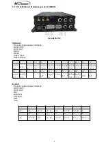
5.7. Pin definition of IO&Serial port on 8ch MDVR

Hero-ME31-08

IO&Serial

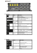
The port contains below interfaces:

DC12V OUT;

DC5V OUT;

RS232;

RS485;

Sensor Input;

Sensor Output;

1

2

3

4

5

6

7

8

9

10

11

12

VCC5V-
OUT

GND

RS232-
RX4

RS232-
TX4

SENSOR
-IN-8

SENSOR
-IN-7

SENSOR
-IN-6

SENSOR
-IN-5

SENSOR
-IN-4

SNESOR
-IN-3

SENSOR
-IN-2

SENSOR
-IN-1

13

14

15

16

17

18

19

20

21

22

23

24

RS232-
TX2

RS232-
RX2

GND

RS232-
B3

RS232-
A3

GND

SENSOR
-OUT-2

SNESOR
-OUT-1

GND

12V

Extend

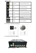
The port contains below interfaces:

DC12V OUT;

DC5V OUT;

MIC;

Audio Out;

CAN BUS;

USB ;

VGA;

1

2

3

4

5

6

7

8

MIC+

GND

CAN-H1

CAN-L1

GND

USB-DP

USB-DM

5V

9

10

11

12

13

14

15

16

12V

GND+GND AOUT

VGA-HS

VGA-VS

VGA-B

VGA-G

VGA-R

Summary of Contents for Hero-ME31-08

Page 1: ...1 User Manual For MDVR ME Series Hero ME40 04 ME41 04 ME3 2 04 ME31 08 Series Howen Technologies LTD 2018 2019...

Page 2: ...9 2 Main menu 14 9 2 1 Search 15 9 2 1 1 Video Searching 15 9 2 1 2 Log search 17 9 2 1 3 Picture search 17 9 2 2 System setting 18 9 2 2 1 Register info 19 9 2 2 2 User 19 9 2 2 3 Time setup 20 9 2 2...

Page 3: ...he housing without authorization to avoid damage or electric shock 2 3 Transport and operation 1 Please use the original package in transport to avoid damage in transport 2 Please keep power off in mo...

Page 4: ...vice may be damaged Power output 12V 2 5A 5V 2A ACC detection 4V Power off 5V Power on Video input impedance 75 Each video input impedance 75 Video output voltage 2Vp p 2VP P CVBS output analog signal...

Page 5: ...5 Hero ME40 04 Attention Hero ME40 04 without 3G and WIFI function so it need not to set the parameters in the menu of 10 2 4 Network setting HDD type MDVR Hero ME31 08...

Page 6: ...switch for device power USB For USB mouse USB flash drive etc LED LED Indicators Green is on status SD HDD LED blinking means it s recording Alarm blinking means there is an alarm AV Out 3 5mm AV out...

Page 7: ...Connect with power adapter battery LAN Connect with network cable for network I O Serial For IO cables Including sensor input sensor output DC power output RS232 RS485 sensor Extend Extension for I O...

Page 8: ...ces DC12V OUT DC5V OUT RS232 RS485 Sensor Input Sensor Output Video Out Audio Out Speed pulse MIC Hero ME41 04 1 2 3 4 5 6 7 8 9 10 11 12 13 14 15 VCC12V OUT GND RS232 RX1 De bug RS232 TX1 De bug Spee...

Page 9: ...SOR IN 8 SENSOR IN 7 SENSOR IN 6 SENSOR IN 5 SENSOR IN 4 SNESOR IN 3 SENSOR IN 2 SENSOR IN 1 13 14 15 16 17 18 19 20 21 22 23 24 RS232 TX2 RS232 RX2 GND RS232 B3 RS232 A3 GND SENSOR OUT 2 SNESOR OUT 1...

Page 10: ...play 4 screens You can press number 1 2 3 4 to display channel 1 channel 2 and channel 3 and channel respectively Return key Return to the previous menu and finally exit from the setup menu to the mon...

Page 11: ...start functional test 6 Device and installation Take ME31 08 HDD SD for example the other models operation are same 1 Unlock the electric lock on front panel Hero ME31 08 2 Install disk Just need to p...

Page 12: ...oring or remote monitoring and applicable for general or special vehicles It mainly uses the special designed vehicle camera to acquire the front video signal then transmits the signal via a special v...

Page 13: ...ll not transmit the data to server You can play on the device directly or by MDVR player get the map information and video 8 Menu structure 9 System operations 9 1 User login New Firmware For all devi...

Page 14: ...call the keyboard page to input password If any err while inputting press Delete button to delete With USB mouse Please connect a USB mouse with MDVR to setup the menu Right click on the live video i...

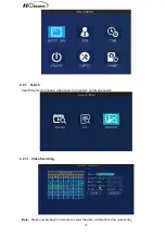
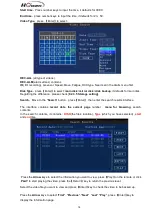
Page 15: ...15 9 2 1 Search Searching menu includes video search log search and image search 9 2 1 1 Video Searching Date Press number keys on remote to select the date it defaults for the current day...

Page 16: ...Search Move to the Search button press Enter then enter the search results interface The interface contains record date the current page number menu for browsing search contents In the search content...

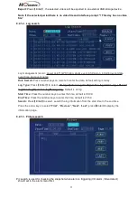
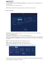
Page 17: ...Type Press Enter to select All log System log Configuration log Alarm log Record log Clear log Operation log Manage log Default is all log Start Time Press the number keys to enter the time default is...

Page 18: ...s 23 59 Search Press Enter to select search the log information from the start time to the end time Press the arrow keys to select First Previous Next Last press Enter key to display the information p...

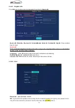
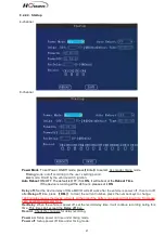
Page 19: ...s very important since we will add this device to the server by these numbers Language press Enter to select and system will reboot automatically Position Mode GPS GLONASS BD and so on License1 2 RFID...

Page 20: ...s GPS Time out Setup Menu Waiting Time once overtime it will automatically log off the current user back to the monitoring mode Press Enter to select 1 minute 2 minutes 5 minutes 10 minutes Default is...

Page 21: ...ff time MDVR will still work after the vehicle is power off then turn off after Delay off time press DEL to clear the current number press the number keys to change 1440 minutes means the device will...

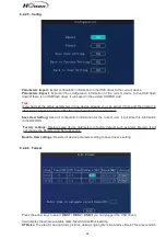
Page 22: ...rt it will reboot automatically Save User Setting Save all configuration information for the current user it will store this information in the SD HDD Factory settings Restore some device parameters t...

Page 23: ...block read write technology It s not recording by time length So if you need save a long time period video change a bigger value for it Format If there is some err with the disk format it It will take...

Page 24: ...is 1080P 1MP is 720P mode D1 definition is less than 1MP Attention this setting must be same with cameras or else it will not display video For example You have 4 1080P and 4 D1 cameras choose item Yo...

Page 25: ...t 1 8 1 is best but it will cost more storage space AUDIO Press Enter to select On Off ON means the audio will be saved with video together Mirror Flip Set the image to mirror or flip Press Enter to s...

Page 26: ...6 219 198 176 CIF 351 264 211 176 153 137 123 110 Sub stream Resolution Image Quality Level 1 2 3 4 5 6 7 8 Bitrate Kbps D1 1500 1300 1100 900 800 700 600 500 HD1 1300 1200 1000 800 700 600 500 400 CI...

Page 27: ...twork transmission the default setting is CIF and fixed 2 QUA 1 is best for saving the 3G 4G data Please choose 7 or 8 9 2 3 4 Timed recording Setting the start time and end time of timing record pres...

Page 28: ...tion Set the alarm file protection time this files will be not deleted during the setting days Press number keys to enter 0 to 45 days Protect Switch Close or Open When it s open then you can set the...

Page 29: ...es USR DEF Press Enter to select Enable on off press number keys to enter the X and Y coordinates USER Define You can define every channel a name by yourself press Enter to call out the keyboard and i...

Page 30: ...tocol It contains H protocol R protocol Transpt etc H protocol is Howen protocol our own protocol if you need to link the third party FMS platform GPS Interval The time interval for sending the GPS da...

Page 31: ...on ask for your ISP supplier or IT team for help When connect the IPC camera make sure the IPC s address in the same segment with LAN For example if the LAN address 192 168 1 010 the IPC address could...

Page 32: ...ct NONE WEP TKIP AES Work Mode Station or AP Station is default setting which enable the device link the internet or router s wireless signal AP Access point mode the device will share a hot spot for...

Page 33: ...oor other doors low beam light high beam light turn right light turn left light brake back Customer definition Press Info key to call out the keyboard for new firmware Level Press Enter to select high...

Page 34: ...will output a DC12V voltage when alarm is triggered Buzzer Need PCB support this component Snap up It will capture the picture while alarm is triggering And save in the SD HDD Preview Press Enter to s...

Page 35: ...a continuous triggering Wait The waiting time in case of mistaken judgement or just wait Press number keys to set Record Turn on off recording function Press Enter to select On Off Alarm link Press E...

Page 36: ...ecord Turn on off recording function Press Enter to select On Off Alarm link Press Enter to select OFF Output 1 Output 2 Buzzer Delay Linkage s duration time Press number keys to set Adjust After you...

Page 37: ...ction For 8 channel device we suggest choose 4 channels at most For 4 channel device we suggest choose 2 channels at most 9 2 5 5 Voltage alarm If the operation voltage is low it will trigger the alar...

Page 38: ...ice COM1 COM2 is RS232 COM3 is RS485 Attention COM1 is for RX1 TX1 COM3 is for RX2 TX2 For different external device the setting is different We will provide the corresponding installation manual for...

Page 39: ...ress and control it Press number keys to enter Preset Preset location when the system start up You can set the PTZ lots of the location first and then choose one of them as the preset location 9 2 5 8...

Page 40: ...c button G sensor It shows the G sensor value Move the MDVR check if this value is changing GPS info It will show as GPS N Location data N is satellite numbers more than 3 is normal No work there is n...

Page 41: ...rent linked WIFI SSID WIFI signal WIFI signal intensity 100 100 is best WIFI IP If the device had linked the wireless network it will get a IP address Server 1 2 Check if the CMS server IP has linked...

Reviews: