5
Mains voltage connection
•
The power supply is 230 V AC; +/-10%.
•
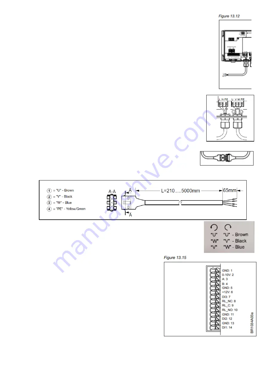
The power cable is connected to the DRHX on the terminals marked ”L”, ”N” and ”PE”.
See fig. 13.12, or table 11 on page 2.
•
It is recommended that the PE wire is 20 mm longer than the other wires in the cable.
If the cable is accidentally pulled out of the DRHX while there is voltage on the cable
and terminals, the PE wire will then be the last to be disconnected.
DRHX is thus prevented from causing electric shock.
•
When the stripped wire is properly inserted into the terminal the terminal automatically
tensions.
•
Remember to
re-tighten the cable glands
to ensure the ingress protection level
of the DRHX and to provide cable strain relief.
Cable
•
Because the stepper motor cable from factory is directly connected into the motor
windings,
it is not allowed to be replaced nor shortened
.
•
The motor cable is correctly assembled when the locking pawl on both sides of
the connector is locked in place with the connector from the cable from the DRHX
(extension cable).
•
The connector can be separated again by releasing the locking pawl on both
sides of the connector on the motor cable and pulling the 2 connectors apart.
•
The extension cable should be connected to the terminals marked:
U
– Brown, V - Black, W – Blue, PE - Yellow/Green
•
If rotation of rotor is wrong:
switch the "V" (black) and "W" (blue) cable to change motor direction.
Analogue/digital signal connections
•
Connect A/D control signals to the terminal strip,
see fig. 13.15. 0-10V = terminal 1 + 2
•
Max. wire dimension is 0.75 mm2 for control terminals.
•
For further information on using the spring terminals,
see fig. 13.10.1
0-10 V control Which terminals!
•
DRHX is factory-configured for 0-10 V control (this can
be changed Modbus operation*)
•
The motor starts when there is a control signal over 1.1 V
(threshold value)
•
The motor stops when control signal is less than 0.6 V
•
The motor runs at maximum speed when there is a control signal over 9.5 V
*RS-485 interface control: DRHX can be controlled via Modbus or BACnet MSTP commands according to
the Modbus / BACnet MSTP protocols (see separate documentation on OJ Electronic homepage)


