Hougen 10925 Operator'S Manual Download Page 4

4

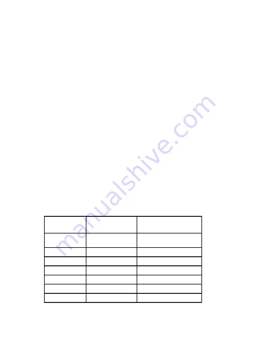
Table 1 Extension Cord Reference Chart

Unpacking Your New Portable Magnetic Drill

1. Open shipping carton and remove the literature and
    hardare packages.
2. Read and follow all Instructions before attempting
     to operate your new Magnetic Drill.
3. Complete and mail the Product Registration Card
     NOW. It is important that Hougen Manufacturing, Inc.
     have a record of product ownership.
4. Open hardware package and check contents.
     10565 1/8” Allen Wrench for Gib Adjustment
    10569 Feed handles (3)
    10570 Feed handle knobs (3)
     10727 3/16” Allen Wrench for reversing feed handle.
     10730 Safety Chain
     10779 7/32” Allen Wrench for cutter installation
     13013 5/32” Allen Wrench for arbor installation and
       

microswitch adjustment

5.  Using the handle of the Magnetic Drill, lift unit out of
      

the shipping case.

6. Remove all packing and securing material from the
    drill unit.
7. Screw the three Knobs (10570) onto the three feed
    handles (10569) and then screw the handles into the
    hub .
8. Your Magnetic Drill was factory adjusted prior to shipping.
    Check to make sure that all gib adjustment screws,
    motor mount screws, front support bracket screws, and
    magnet mounting screws are snug and have not vibrated
    loose in transit.
9. Your New Magnetic Drill comes complete with arbor
    mounted. The 3/4” diameter arbor bore fits all 3/4” -
    shank “12000-Series” Rotabroach Cutters. A 1/2”
    diameter boreArbor Adapter (10851), for mounting1/2”
    shank “12,000-Series” Rotabroach Cutters, is optional.

Recommended cutting capacity when using “12,000-Series” Rotabroach Cutters-
Power Feed Mode

Manual Feed Mode

2” diameter maximum - 1” depth of cut

2-1/16” diameter maximum - 1” or 2” depth of cut

1-1/2” diameter maximum - 2” depth of cut

2” diameter maximum - 3” depth of cut

1-1/16” diameter maximum - 3” depth of cut

Actual cutting capacity may vary based on application. Feed setting chart on panel is recommended starting
point for diameter range. Adjustments may be needed for optimum cutting performance

Cutting Capacity

Length of Cord,

Feet

Recommended Wire

Gauge

Recommended Wire  Gauge

115V Motor

10-12 Amps

230V Motor

 5-6 Amps

Up to 25

16

18

26-50

14

18

51-100

10

16

101-200

8

14

201-300

6

12

301-500

4

10

Summary of Contents for 10925

Page 1: ...PORTABLE MAGNETIC DRILLS OPERATOR S MANUAL FOR USE WITH 12 000 SERIES ROTABROACH CUTTERS 10925 AND 10926...

Page 2: ...Bracket Installing Arbor Assembly Page 9 Safety Switch Adjustment Removing Arbor Assembly Maintenance Hints for Smoother Operation Page 10 Power Feed Gear Motor Breakdown Adjusting Depth of Cut Diagra...

Page 3: ...10 Imperial Court Brampton Ontario Canada L6T 4X4 905 458 4800 Power Tool Clinic 19835 56 Ave Langley B C Canada V3A 3V1 604 530 3550 O T I Repair Center Inc 195 Rue Henry Bessemer Bois Des Filion Que...

Page 4: ...tic Drill was factory adjusted prior to shipping Check to make sure that all gib adjustment screws motor mount screws front support bracket screws and magnet mounting screws are snug and have not vibr...

Page 5: ...d 3 pole receptacles that accept the tool s plug Replace or repair damaged cords Make sure the conductor size is large enough to prevent excessive voltage drop which will cause the loss of power and p...

Page 6: ...es replaced by authorized service center 20 Additional Safety Precautions Arbor and cutter should never be used as a hand hold Keep hands and clothing away from all moving parts Do not use Rotabroach...

Page 7: ...itch Tighten thumb screw 5 Manually move slide up approximately 1 4 6 Turn on drill and manually feed slide until shut off to test for proper shut off position INSTALLING ROTABROACH CUTTER IN ARBOR 1...

Page 8: ...d the retaining clip into its groove 5 Adjust and tighten arbor support bracket before using drill See arbor support bracket adjustment procedure 5 Screw Impactor Point 1 4 1 3 turn further toward wor...

Page 9: ...ect Mag Drill from power source 2 Remove the bottom cutting fluid inducer retaining ring 40302 from its groove and slide down about 3 4 inch 3 Dis connect the coolant tube fitting and tube 4 Slide the...

Page 10: ...10 POWER FEED GEAR MOTOR...

Page 11: ...uid is visible filling the plastic tube Fluid should filter down onto the work surface through the groove in the pilot 4 To insure proper cutter lubrication always make sure that the slot in the pilot...

Page 12: ...clutch disengaged Proper lubrication between the hub 01124 and segmented ring 01140 will reduce or eliminate the need for readjust ment from original factory settings by lubricating the unit periodic...

Page 13: ...p ut 1 20 4 02 77 P i n Lo cati ng 1 21 4 03 50 Gre as e S ynte ch 8 oz 22 4 02 79 B e ari ng 1 23 4 02 80 B a ll 1 24 4 02 81 S lug 1 D e tail N o Pa rt N o D e sc rip tio n N o R e q d 25 4 03 83 S...

Page 14: ...14 10925 10926 Power Feed Assembly...

Page 15: ...10925 10926 Mechanical Breakdown 15...

Page 16: ...16 Electrical Panel Layout Diagram...

Page 17: ...17 Electrical Panel Hook up Diagram...

Page 18: ...1 01353 CONTROL PANEL ASSY 230V 1 01376 MAGNET ASSY 230V 1 Part No De scriptio n Qty Req d 01993 HEX B OLT 10 32 X 3 4 3 02153 PO TE NTIOM ETER 1 02185 HIG H S PE ED GE AR 1 02186 G EA R INTE R HIG H...

Page 19: ...MOTOR M OUNT S LIDE 1 40295 INDUCE R RING 1 40297 S CR B HC 6 32 X 1 2 4 40299 SPACER 3 4 B LOCK 1 40300 O RING 2 40301 THRUST WA SHER 2 40302 RE TA INING RING 2 40303 FITTING 1 40309 CORD CLAMP 1 403...

Page 20: ...o state To obtain warranty service return the item s transportation prepaid to your nearest Factory Authorized Warranty Repair Center or to Hougen Manufacturing Inc 3001 Hougen Drive Swartz Creek Mich...

Reviews: