background image

Page 9

Hotsy 5645  •  97-6850  •  Rev. 8/03

To Start

DANGER:  DO NOT point wand or spray gun at your-
self or at any person. Bodily injury may result from
water under high pressure.

IMPORTANT: The water must be turned on before
starting. Running the pump dry will cause damage
and void warranty.

IMPORTANT: DO NOT allow the machine to run with
trigger gun closed for more than 3 minutes at any
time or damage to pump may occur.

1. Turn water ON.

2. Hold wand firmly with trigger gun in the closed posi-

tion.

3. Turn fuel shut-off valve counterclockwise (CCW) to

open. Move choke lever to full choke position. Choke
may not be needed on warm engine.

4. Move throttle control to half throttle.

5. Turn key on engine clockwise (CW) hold until engine

starts. 

DO NOT

 crank engine for longer than 15 sec-

onds at any one time or starter damage may occur. If
the engine does not start, it may have air in the gas
lines and be unable to pull gasoline from the fuel tank.
This symptom may appear if the engine has not been
run recently or had been run until all gasoline was
depleted from gas lines.

6. When the engine starts, move choke lever until

engine runs smoothly. Then move throttle control to
full throttle. When engine warms, move choke to no
choke position.

IMPORTANT: To allow for proper battery charging and
AC generator operation the throttle control MUST be
kept in full throttle position as soon as choke lever is
placed in no choke position.

7. Holding wand firmly, squeeze the trigger gun open.

Allow air to purge from system.

8. If hot water is desired, adjust the thermostat to

proper temperature. Close the trigger gun and turn
burner switch ON.

IMPORTANT: The throttle control must be in the full
throttle position or damage to the AC generator or
burner may result.

9. Open the trigger gun. The burner will fire immediately

with a puff of smoke. If smoke continues, refer to the
Troubleshooting Guide in this manual. When the trig-
ger gun is closed or the temperature setting is
reached, the burner will automatically turn off.

To Clean

1. Insert the detergent inlet line into the container of

mixed detergent. The detergent metering valve can
be opened gradually to meter the desired amount of
detergent. The flow may be observed through the clear
detergent line. Allow detergent to reach the end of
wand before proceeding.
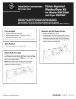
Pressure Nozzle

Figure 8 - Nozzle Installation/Manual Trigger Lock

Manual Trigger  Lock

6. If detergents are to be used, only use detergent for

pressure washers. Follow instructions on detergent
container.

IMPORTANT: Before installing the pressure nozzle
on initial start-up, turn on the water supply and allow
water to run from the end of the wand until clear to
prevent the pressure nozzle from clogging.

IMPORTANT: If the pressure washer has not been
used for an extended period of time, remove the pres-
sure nozzle from the end of the wand and turn on the
water supply. Allow water to run from the end of the
wand until clear.

7. Install the proper pressure nozzle for your cleaning

needs on end of wand, refer to 

Figure 8.

IMPORTANT: The trigger gun provided with this pres-
sure washer is equipped with a manual trigger lock
to prevent accidental operation of the trigger gun,
refer to Figure 8. The manual trigger lock should be
used whenever the trigger gun is not in use.

Fuel Pump

The model 5645 is equipped with an electric fuel pump
which operates only when the engine is running. The
pump is primed when the key switch is held in the start
position. In the event that the engine stalls for any reason
the fuel pump will shut off.

WARNING: The fuel pump installed on this machine
has been adjusted at the factory to provide a maxi-
mum pressure of 1.3-1.7 PSI at the pump outlet. When-
ever the fuel pump is replaced the new pump must
be adjusted using the following procedure:

1. Place the ignition switch in the OFF position.

2. Disconnect the fuel line from the engine mounted fuel

filter and connect a fuel pump pressure gauge  (0-5
PSI) to the fuel pump discharge line.

3. Turn the ignition key to the start position and

observe pressure gauge. Pressure must be set to
between 1.3 and 1.7 PSI. It will be necessary to bleed
off accumulated pressure in line prior to each gauge
reading. Turn screw on top of fuel pump to adjust pres-
sure (CCW to decrease, CW to increase).

4. After adjustment, reconnect fuel line to engine

mounted fuel filter and start machine. Check for fuel
leakage and tighten fittings/clamps as required.

Summary of Contents for 5645

Page 1: ...NVERNESS WAY EAST ENGLEWOOD CO 80112 303 792 5200 WWW HOTSY COM DATE PURCHASED FOR SALES AND SERVICE PLEASE CONTACT SPECIFICATIONS Pump Volume At Pump Head 6 0 GPM 360 GPH Pump Pressure At Pump Head 3000 PSI Burner Type Fuel Oil Fired 528 000 BTU Hr Burner Fuel Pressure 135 PSI Machine Power 24 HP Gasoline Engine Electric Start Machine Weight 1025 Lbs Shipping Weight 1200 Lbs Exhaust Stack Size 8 ...

Page 2: ......

Page 3: ...ury from a whipping wand WARNING Highpressurestream of fluid that this equipment can produce can pierce skin and its underlying tissues leading to serious injury and possible am putation 9 High pressure developed by these machines can cause personal injury or equipment damage Use caution when operating Do not direct discharge stream at people or severe injury and or death may result 10 Never make ...

Page 4: ...yout High Pressure Outlet Float Tank Detergent Inlet Hoses Fresh Water Inlet Unloader Valve Burner Exhaust Battery Box Pump Engine Key Switch Burner Fuel Tank Engine Gas Tank High Pressure Hose Control Panel Burner Switch Hour Meter Porta Gear Kit Optional ...

Page 5: ...d 1 12 817313 Cap Tankw GasGauge 1 13 241207 Coil Oil 22 1 NotShown Figure 2 Machine Component Layout 4 8 1 2 3 6 5 11 9 12 10 7 Ref No PartNo Description Qty 1 886538 Meter HourACw U Bracket 1 2 875858 SwitchRockerw NeonLight 1 3 835150 DialThermostat32 248 F 1 915390 PlateMountingThermostat 1 955930 Thermostat w MeterCapillary 1 4 971576 Valve Detergent DualMetering 1 5 785061 MufflerTopMount 1 ...

Page 6: ...gation Responsibility The owner and or user must have an understanding of the manufacturer s operating instructions and warnings before using this Hotsy pressure washer Warning in formation should be emphasized and understood If the operator is not fluent in English the manufacturer s in structions and warnings shall be read to and discussed with the operator in the operator s native language by t...

Page 7: ...ient supply of oxygen Proper combustion can only be obtained when there is a sufficient supply of oxygen available for the amount of fuel being burned If it is necessary to install the machine in a poorly ventilated area outside fresh air will have to be supplied to the machine Locate the pressure washer so that the flue will be as straight as possible and protrude through the roof at a proper hei...

Page 8: ...For proper operation it is important that the valve be fully open for its intended supply This will prevent air from being drawn into the system from the nonactive source Also the pressure supply must still be connected to the float tank The connection of a pressurized supply directly to the 3 way valve will prevent detergent from being drawn into the system Figure 7 Gravity Tank Plumbing Connecti...

Page 9: ... valve can be opened gradually to meter the desired amount of detergent The flow may be observed through the clear detergent line Allow detergent to reach the end of wand before proceeding Pressure Nozzle Figure 8 Nozzle Installation Manual Trigger Lock Manual Trigger Lock 6 If detergents are to be used only use detergent for pressure washers Follow instructions on detergent container IMPORTANT Be...

Page 10: ...antifreeze through system for several minutes Open and close the trigger gun several times to circulate antifreeze through the unloader valve Place detergent line into the float tank Open the detergent metering valve to draw antifreeze into the detergent system If the pressure washer is not to be used for a considerable length of time it is recommended to flush the system with antifreeze for rust ...

Page 11: ...inadequate combustion air will cause heavy soot buildup on the outside surface of the heating coil This will restrict the airflow through the coil further aggravating the soot buildup Contact your local service center when desooting is needed Engine Refer to engine manual provided with this pressure washer for recommended maintenance Oil Burner Blower Motor The motor bearings are permanently lubri...

Page 12: ... NPTx1 4 1 5 615285 Bushing Reducer1 2 x3 8 1 6 935165 Screen Suction 1 Figure 9 Pump Assembly 1 3 9 11 7 5 4 8 6 2 13 12 10 Ref No Part No Description Qty 7 954717 Tee 1 2 x3 8 STR 2 8 644754 Elbow 1 2 STL 1 9 644601 Elbow 3 4 JICx1 2 NPT 1 1 0 HC800 Pump HC800 1 1 1 644602 Swivel 3 4 Push On 1 1 2 644603 Swivel 1 2 Push On 1 1 3 644600 Elbow 1 2 JIC 1 OrderAmountInFeet ...

Page 13: ...ure 10 Unloader Valve Assembly 3 4 6 5 2 1 Ref No PartNo Description Qty 1 875651 PressureSwitch 1 2 971580 UnloaderValve 3000PSI 1 3 801102 Nipple 3 8 Hexx1 45 1 4 698025 Nipple 3 8 NPTx1 2 H 1 5 644751 Elbow 3 8 1 6 815220 Bush 1 2 x3 8 1 ...

Page 14: ...age 14 Hotsy 5645 97 6580 Rev 8 03 Figure 11 Float Tank Assembly 2 1 4 3 Ref No PartNo Description Qty 1 334937 RodTHD 1 4 x11 1 2 807169 Ball PlasticFloat4 1 3 952721 Tank Float 1 4 971421 FloatValve 1 ...

Page 15: ...ulley Assembly Ref No PartNo Description Qty 1 875061 Generator 1 2 919541 Pulley BK40H 1 3 809150 Belt BX22 1 4 830569 Pulley 3TB40 1 5 815200 Bushing P1x11 8 1 6 809010 Belt BX41 2 7 919560 Pulley 2BK100 1 8 815131 Bushing Hx5 8 1 3 1 2 7 6 5 4 8 ...

Page 16: ...4 5 Ref No PartNo Description Qty 1 867361 Hose 1 4 ID 250PSI Grip Red 2ft 2 952731 FuelTank Red 1 3 815230 Bushing 1 4 676575 Elbow 1 4 HosexStand Pipe 1 5 817313 FuelTankCapw Gauge 1 6 444432 FuelTankDecal 1 7 830491 Pump 12VFuel Facet 1 8 615533 Screw 1 4 x3 4 HHNC WhizLoc 2 Figure13 EngineFuelTankAssembly To Engine 5 6 3 4 2 9 7 8 1 10 10 11 12 12 12 3 4 12 Fuel Pump Assembly 1290SSG Model Onl...

Page 17: ...bly Ref No PartNo Description Qty 1 844595 Elbow 1 4 x1 4 Hose 1 2 676575 Elbow 1 4 HosexStandPipe 1 3 815230 Bushing 1 4 952730 FuelTank Black 1 Ref No PartNo Description Qty 5 817312 FuelTankCapw Gauge 1 6 444433 FuelTankDecal 1 7 971186 FuelValve 1 2 7 1 5 6 4 3 ...

Page 18: ...Page 18 Hotsy 5645 97 6580 Rev 8 03 Figure 15 Pump Assembly ...

Page 19: ...926649 BearingHousingO Ring 2 28 926651 CrankshaftSeal 2 29 808401 RollerBearing 2 30 827399 Double Ended Crankshaft N A Ref No PartNo Description Qty 31 N A Single EndedCrankshaft N A 32 877399 CrankshaftKey8x7x25mm 1 33 835280 OilDipstick 1 34 944784 Shim 2 35 PlungerAssemblyBolt 3 36 CopperSpacer 3 37 PlungerRodO Ring 3 38 TeflonRing 3 39 PlungerSleeve25mm 3 40 CopperSpacer 3 41 829931 PlungerR...

Page 20: ...Nozzle 1 4 723367 ElectrodeAssembly 1 5 830493 FuelPumpw 115VSolenoid 1 6 698020 Nipple 1 4 NPTx1 4 Hose 2 7 823988 Clamp Hose UNI 46 54 2 8 783814 Motor115V 1 Ref No PartNo Description Qty N S 848608 BlowerFan 1 N S 848609 FanCoupling 1 N S 851140 Filter Fuel Oil 1 N S 944840 FuelPumpStem 1 N S 944841 FuelPumpScreen 1 N S 826167 StrainRelief 1 N S 703127 StrainReliefNut 1 NS NotShown ...

Page 21: ...ure nozzle clogged Clean Low pressure from spray nozzle Inlet clogged Clean Spray nozzle worn or incorrect size Replace Inadequate water supply Increase water supply Pump sucking air Fill the detergent container Check for loose hose clamps or fittings Unloader valve cycles when trigger gun is open or closed Air in system Open and close trigger gun several times Defective unloader valve Repair or r...

Page 22: ...not correct the problem contact the local authorized Hotsy Service Center The Hotsy Service Center can be identified by contacting Customer Service Department The Hotsy Corporation 21 Inverness Way East Englewood Colorado 80112 303 792 5200 When ordering from your dealer please provide the following Model Number 5645 Machine Serial Number ________________________________ Component Part Number ____...

Page 23: ...Page 23 Hotsy 5645 97 6580 Rev 8 03 Figure 16 Wiring Diagram ...

Page 24: ...d describe the product in this literature accurately however such illustrations and descriptions are for the sole purpose of identification and do not express or imply a warranty that the product is merchantable or fits a particular purpose or that the product will necessarily conform to the illustrations or descriptions PRODUCT SUITABILITY Many states and localities have codes and regulations gov...

Reviews: