26 of 28
Service Manual UK
Indesit
Company
English
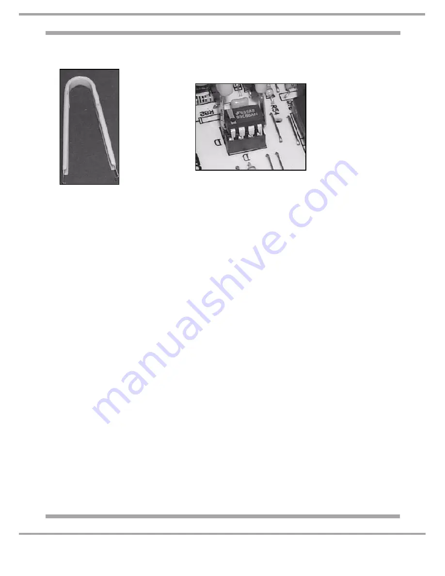
On the original control board, the EEProm may be soldered to the board and cannot be removed.
IC Removal Tool
EEPROM Removal from PCB
Page 1: ...Ltd 2007 Reg Office Peterborough PE2 9JB Registered in London 106725 Service Information WASHING MACHINES Models Comm Covered Code LED ARXXL105EU 47553 ARXXL105IT 51215 DIGIT ARXXF125EU 49055 5407388...
Page 2: ...od Centres etc checks must be made for leaks from seals gaskets and pipe work and rectification carried out where necessary 7 It can be dangerous to attempt DIY repairs maintenance on complex equipmen...
Page 3: ...mation 2 Development History 3 Specifications 4 Controls 5 6 Options 7 Demo Mode ARXXF125EU 8 Controls Information 9 Option Availability 10 Wiring Diagrams LED 11 Digit 12 Wiring Connection Chart 13 W...
Page 4: ...Heater 1800 Watts 230 volts Resistance 30 approx Thermistor NTC Resistance 20 K 20 C Pump 2 Pole Synchronous 220 240 Volt 25 Watt Resistance 162 Door Lock P T C Solenoid with emergency door release To...
Page 5: ...lect the Option you require a time will be indicated in the display window Press the Start Cancel button A beep will be heard followed by a CLUNK from the door lock Solenoid as it locks the door at th...
Page 6: ...you press the START PAUSE button and will stay lit throughout the programme When the programme has finished the indicator light will go out and you can then open the door a double CLUNK noise will be...
Page 7: ...ion to reducing actual washing time this option will reduce water and energy consumption by up to 50 NOTE You can reduce the amount of detergent you use with this programme EXTRA RINSE For large wash...
Page 8: ...MODE ARXXF125EU To Activate Demo Mode Press and hold the following buttons simultaneously ON OFF BUTTON EASY IRON START PAUSE To De select Demo Mode Press and hold the following buttons simultaneously...
Page 9: ...achieved by energising both the Pre Wash and Main Wash cold valves Out of Balance Protection The machine has an inbuilt feature to prevent spinning with an unbalanced load A calculation via the motor...
Page 10: ...the cycle the washing will be suspended in water avoiding the main noise created during the final phase BABY Temperature 40 C Spin 800 rpm Load 2 0 kg Cycle duration 1 Hour 50 minutes This cycle will...
Page 11: ...2 3 4 1 2 3 4 1 C 3 4 6 7 9 1 EMPTY FULL COMMON GND RX 1 2 3 4 6 7 8 R R 5 6 D j5 j1 j3 j8 j10 j2 j4 12A 12A 10A 10A 8A 10A 10A 1A 1A 10w 10w 10A 1 2 RTN_IP RTN_PORTA 8 9 j11 1 2 3 4 5 1 2 3 4 5 1 1 2...
Page 12: ...5 R R R Test 1 3 1 2 1 2 1 2 2 3 4 1 2 3 4 1 C 3 4 6 7 9 1 EMPTY FULL COMMON GND RX 1 2 3 4 6 7 8 R R 5 6 D j5 j1 j3 j8 j10 j2 j4 12A 12A 10A 10A 8A 10A 10A 1A 1A 10w 10w 10A 1 2 RTN_IP RTN_PORTA 8 9...
Page 13: ...EN 2J3 3J3 4J3 5J3 6J3 4 3 2 1 3 2 1 3 1 1 3 1 3 1 1 FA4 FA1 J1 J3 1J9 2J9 3J9 4J9 5J9 6J9 7J9 8J9 9J9 IJ11 2J11 3J11 4J11 5J11 5J15 4J15 3J15 2J15 1J15 7 6 5 4 3 2 1 2 1 J9 J11 J4 J8 Motor Pump Displ...
Page 14: ...tat SR Heating indicator light FE Intense drying thermostat ST Temperature selector or Stop with water FRT Thermofuse resistance SV Spin speed selector I Reverser T Timer contacts I1 I2 3 Switches dev...
Page 15: ...15 of 28 Indesit Company Service Manual UK English POWER MODULE CONNECTIONS J11 J8 J10 J13 J14 J15 J9 J2 J1 J4 J3 AUTO TEST SOCKET external EEPROM SOCKET modules only Service spares J5...
Page 16: ...s F08 Heater relay stuck Check pressure switch heater and module connections F09 Setup error Check Eeprom F10 Pressure switch not sensing Check switch and module connections F11 Pump cannot be activat...
Page 17: ...and lift off B Lower Rear Access Panel 1 Remove three screws from the lower rear access panel 2 Pull the top edge of the panel out and disengage it from its location fixings along the bottom C Dispen...
Page 18: ...ket from the cabinet side and then unclip the switch from the bracket H b Front Panel 1 Remove the table top A dispenser drawer C and console panel 2 Remove the door seal restraint I and door interloc...
Page 19: ...front panel and fold it back into the inner drum 3 Remove 2 screws from the interlock 4 The interlock can now be eased out allowing access to the wiring connection block and emergency release strap 5...
Page 20: ...m the door aperture to move the belt into position 5 Ensure any remaining tie wraps are removed It is essential for continued safety that only a genuine spare is fitted The belt is electrically conduc...
Page 21: ...nner remove three balance weight fixing screws 4 Pull the weight forward off its mounting lugs 5 When refitting the balance weight it is essential to ensure that the thread forming screws are tightene...
Page 22: ...e pulley security always apply an engineering Nutlock Part No 981009 to the bolt threads T a Suspension Damper 1 Remove two suspension clamp fixing screws 2 Remove the table top A dispenser drawer C a...
Page 23: ...he valve cover to the cabinet and remove the cover 5 Ease the dispenser backwards 6 Remove the dispenser inlet and outlet hoses and any harness retention ties V Drain Pump 1 Remove the appliance kick...
Page 24: ...to be transferred from the faulty drum assembly 1 Remove the table top A 2 Remove the top balance weight Qb 3 Remove the dispenser drawer C 4 Remove the console panel D 5 Remove the dispenser U 6 Remo...
Page 25: ...IDING ELECTRICAL DAMAGE TO THE MODULE Before disconnecting any plugs it is advisable to note their locations When reconnecting the plugs to the module it is essential that the large WHITE multiway edg...
Page 26: ...26 of 28 Service Manual UK Indesit Company English On the original control board the EEProm may be soldered to the board and cannot be removed IC Removal Tool EEPROM Removal from PCB...
Page 27: ...27 of 28 Indesit Company Service Manual UK English...
Page 28: ...28 of 28 Service Manual UK Indesit Company English...